EP1333191A1 - Support antivibratoire hydraulique - Google Patents
Support antivibratoire hydraulique Download PDFInfo
- Publication number
- EP1333191A1 EP1333191A1 EP03290192A EP03290192A EP1333191A1 EP 1333191 A1 EP1333191 A1 EP 1333191A1 EP 03290192 A EP03290192 A EP 03290192A EP 03290192 A EP03290192 A EP 03290192A EP 1333191 A1 EP1333191 A1 EP 1333191A1
- Authority
- EP
- European Patent Office
- Prior art keywords
- collar
- cage
- shoulder
- support
- extending
- Prior art date
- Legal status (The legal status is an assumption and is not a legal conclusion. Google has not performed a legal analysis and makes no representation as to the accuracy of the status listed.)
- Granted
Links
- 229920001971 elastomer Polymers 0.000 claims abstract description 18
- 239000000806 elastomer Substances 0.000 claims abstract description 18
- 238000013016 damping Methods 0.000 claims abstract description 4
- 230000002787 reinforcement Effects 0.000 claims description 23
- 238000002788 crimping Methods 0.000 claims description 14
- 238000000465 moulding Methods 0.000 claims description 7
- 239000000463 material Substances 0.000 claims description 6
- 229910052782 aluminium Inorganic materials 0.000 claims description 5
- XAGFODPZIPBFFR-UHFFFAOYSA-N aluminium Chemical compound [Al] XAGFODPZIPBFFR-UHFFFAOYSA-N 0.000 claims description 5
- 229910000831 Steel Inorganic materials 0.000 claims description 4
- 239000007788 liquid Substances 0.000 claims description 4
- 239000010959 steel Substances 0.000 claims description 4
- 238000006073 displacement reaction Methods 0.000 claims description 2
- 239000012530 fluid Substances 0.000 abstract 1
- 238000004519 manufacturing process Methods 0.000 description 3
- 208000031968 Cadaver Diseases 0.000 description 2
- BASFCYQUMIYNBI-UHFFFAOYSA-N platinum Chemical compound [Pt] BASFCYQUMIYNBI-UHFFFAOYSA-N 0.000 description 2
- 239000004411 aluminium Substances 0.000 description 1
- 239000000470 constituent Substances 0.000 description 1
- 229910052751 metal Inorganic materials 0.000 description 1
- 239000002184 metal Substances 0.000 description 1
- 230000000717 retained effect Effects 0.000 description 1
- 238000007789 sealing Methods 0.000 description 1
- 238000003466 welding Methods 0.000 description 1
Images


Classifications
-
- F—MECHANICAL ENGINEERING; LIGHTING; HEATING; WEAPONS; BLASTING
- F16—ENGINEERING ELEMENTS AND UNITS; GENERAL MEASURES FOR PRODUCING AND MAINTAINING EFFECTIVE FUNCTIONING OF MACHINES OR INSTALLATIONS; THERMAL INSULATION IN GENERAL
- F16F—SPRINGS; SHOCK-ABSORBERS; MEANS FOR DAMPING VIBRATION
- F16F13/00—Units comprising springs of the non-fluid type as well as vibration-dampers, shock-absorbers, or fluid springs
- F16F13/04—Units comprising springs of the non-fluid type as well as vibration-dampers, shock-absorbers, or fluid springs comprising both a plastics spring and a damper, e.g. a friction damper
- F16F13/06—Units comprising springs of the non-fluid type as well as vibration-dampers, shock-absorbers, or fluid springs comprising both a plastics spring and a damper, e.g. a friction damper the damper being a fluid damper, e.g. the plastics spring not forming a part of the wall of the fluid chamber of the damper
- F16F13/08—Units comprising springs of the non-fluid type as well as vibration-dampers, shock-absorbers, or fluid springs comprising both a plastics spring and a damper, e.g. a friction damper the damper being a fluid damper, e.g. the plastics spring not forming a part of the wall of the fluid chamber of the damper the plastics spring forming at least a part of the wall of the fluid chamber of the damper
- F16F13/14—Units of the bushing type, i.e. loaded predominantly radially
-
- F—MECHANICAL ENGINEERING; LIGHTING; HEATING; WEAPONS; BLASTING
- F16—ENGINEERING ELEMENTS AND UNITS; GENERAL MEASURES FOR PRODUCING AND MAINTAINING EFFECTIVE FUNCTIONING OF MACHINES OR INSTALLATIONS; THERMAL INSULATION IN GENERAL
- F16F—SPRINGS; SHOCK-ABSORBERS; MEANS FOR DAMPING VIBRATION
- F16F2226/00—Manufacturing; Treatments
- F16F2226/04—Assembly or fixing methods; methods to form or fashion parts
-
- F—MECHANICAL ENGINEERING; LIGHTING; HEATING; WEAPONS; BLASTING
- F16—ENGINEERING ELEMENTS AND UNITS; GENERAL MEASURES FOR PRODUCING AND MAINTAINING EFFECTIVE FUNCTIONING OF MACHINES OR INSTALLATIONS; THERMAL INSULATION IN GENERAL
- F16F—SPRINGS; SHOCK-ABSORBERS; MEANS FOR DAMPING VIBRATION
- F16F2230/00—Purpose; Design features
- F16F2230/0047—Measuring, indicating
Definitions
- the present invention relates to supports hydraulic anti-vibration mounts, especially on supports hydraulic vibration dampers mounted between a motor and a motor vehicle chassis.
- These supports include two frames, a cage and a turntable.
- the fitting, in the external reinforcement, of the assembly consisting of the internal frame, the cage and the elastomer body, as well as crimping or welding of the external armature on the plate, must be made in two separate successive operations.
- Such supports therefore have the disadvantages to have a weight and a manufacturing cost relatively high and having to be mounted in two operations, which requires relatively complex tools.
- the object of the present invention is in particular to overcome these drawbacks.
- a support of the kind in question is characterized by the fact that the collar extends radially outward from the shoulder and has at least a portion of surface in look of the collar, with a body thickness in elastomer interposed between the collar and the collar, by the fact that the collar is directly attached to the collar by crimping, and by the fact that at least one element chosen among the collar and the collar constitutes the plate.
- the plate and the collar or the collar is only one piece, which reduces the number of parts of the support according to the invention with respect to the supports of the prior art, therefore to simplify the manufacture by reducing the number assembly operations. Consequently, this allows to reduce the manufacturing cost and the weight of this type of support.
- the support 1 has an internal frame 2, a cage 3, an elastomer body 4 and a frame external 5.
- the internal frame 2 consists of a rigid tube extending longitudinally along an axis of revolution X.
- the cage 3 consists of a metal sheet rigid and has a tubular wall 6 and a flange 7.
- the tubular wall 6 surrounds the internal frame 2, coaxially with the latter.
- the tubular wall 6 extends, parallel to the X axis, between two axial ends 8 and 9.
- the tubular wall 6 has two windows 10 and 11 substantially diametrically opposite the X axis.
- the presence windows 10 and 11 facilitate the molding of the body in elastomer 4 on cage 3.
- Window 10 on the right in Figures 4 and 5, includes a reinforcement 12 extending longitudinally parallel to the X axis, between substantially the midpoints respective of the two edges of the window 10 perpendicular to the X axis.
- This reinforcement 12 is approximately 10 mm wide.
- the collar 7 extends radially outwards of the support 1, from the axial end 9.
- the end axial 9 is connected continuously with the flange 7.
- the flange 7 continues in a plane perpendicular to the X axis to form a plate 17.
- the collar 7 and plate 17 are in fact made up of a same and unique plate.
- the flange 7 corresponds to the part of this plate covered by the elastomer body 4 and the plate 17 corresponds to the remaining part of this plate.
- the plate 17 has substantially a rectangular shape and comprises means for fixing the support 1 to a external part 26 to this support 1, such as a motor. These fixing means materializing on the plate 17 by holes 18, intended for example for the passage of bolts 27.
- the plate 17 is pierced with four orifices of crimping 19.
- Each crimping orifice 19 is circular and present, in section perpendicular to the plane of plate 17, a flared shaped cut more widely open on the upper face of the plate 17, that is to say that directed in the direction corresponding to the one going from the axial end 8 towards the axial end 9.
- the elastomer body 4 surrounds the internal reinforcement 2 and envelops the tubular wall 6 and the flange 7 of the cage 3. This elastomer body 4 connects the internal reinforcement 2 and the cage 3 by forming two pockets 13 and 14 respectively next to windows 10 and 11.
- the pocket 13 that is to say corresponding to that open to window 10 with reinforcement 12 (right in Figure 4), has an axial section in the form of "U" open radially towards the outside of the support 1 and of which the top is separated from the internal frame 2 by a cavity 15 and a wall 16.
- the pocket 14 has an axial section in the form of "U” or “V” open radially outward from the support 1 and the top of which is linked to the internal reinforcement 2 by the body of the elastomer 4.
- the external frame 5 has a cylindrical part 20 of revolution around the X axis, a shoulder 21 and a collar 22.
- the external frame 5 can be produced by for example steel, aluminum or plastic.
- the external reinforcement 5 is produced by molding plastic, its role is essentially to ensure the tightness of the pockets 13 and 14.
- the cylindrical part 20 closely surrounds the tubular wall 6 of the cage 3, a thin body thickness in elastomer 4 being interposed between the two.
- the part cylindrical 20 continues, towards the lower part of the support 1, that is to say on the side of the axial end 8, by a rim 23.
- This rim 23 extends radially, from the cylindrical part 20, towards the axis X.
- the body in elastomer 4 interposed between the axial end 8 of the tubular wall 6 and this rim 23 constitutes a seal axial sealing.
- the cylindrical part 20 closes the windows 10 and 11 to close the pockets 13 and 14, the elastomer body 4 forming a seal around these windows 10 and 11.
- the cylindrical part 20 continues towards the upper end of the support 1, that is to say on the side of the axial end 9 of the tubular wall 6, by the shoulder 21.
- the shoulder 21 is produced by stamping of the external reinforcement 5 or during a molding.
- the shoulder 21 is formed during this molding.
- the shoulder 21 extends radially towards outside the support 1.
- the shoulder 21 delimits a channel 24 with the part top of the tubular wall 6 located near the axial end 9, and the flange 7.
- This channel 24 is narrow and connects the pockets 13 and 14 extending in a arc of a circle centered on the X axis.
- the connection between each pockets 13 and 14 and channel 24 is carried through windows 10 and 11 and by bent passages formed in the external reinforcement 5 (not visible on the section planes shown).
- the pockets 13, 14 and the channel 24 are filled with a damping liquid L. This liquid moves from a pocket to the other via channel 24.
- the pocket 13 is able to be deform, thanks to the flexibility of the wall 16, when the internal frame 2 is moved relative to the cage 3.
- the shoulder 21 continues radially towards the outside of the support 1, by the collar 22.
- the collar 22 has four chimneys 25 or crimps, coincidentally crimping orifices 19.
- the constituent wall of each chimney 25 is folded over the countersink of the orifice crimping 19 corresponding.
- the external frame 5 is thus retained on the plate 17.
- Each chimney 25 is shaped so as not to protrude on the face top of plate 17, after crimping.
- the support is produced in one operation during which we follow by its face upper (on the side of the shoulder 21) in force the reinforcement internal 2 and the cage 3 in the external frame 5 and fold chimneys 25 in crimp holes 19 correspondents.
- the external reinforcement 5 is made of material plastic, it is advantageously held in place by clipping on deck 17.
- a part of the body of elastomer 4 is compressed between the collar 7 and the collar 22, thus forming a another axial seal.
- a countersink can be formed on the collar 22 rather than on the plate 17, while the chimney 25 is formed on the plate 17, thus reversing the direction of crimping compared to that presented above.
- a crimping of the collar 22 on the edges of the plate 17 can be provided in addition or as a replacement crimping in the crimping holes 19 described above.
Landscapes
- Engineering & Computer Science (AREA)
- General Engineering & Computer Science (AREA)
- Mechanical Engineering (AREA)
- Combined Devices Of Dampers And Springs (AREA)
- Rolling Contact Bearings (AREA)
- Springs (AREA)
- Body Structure For Vehicles (AREA)
Abstract
- une armature interne (2),
- une cage (3) comportant une paroi tubulaire (6) et une collerette (7) s'étendant radialement vers l'extérieur, à partir de la paroi tubulaire (6),
- une armature externe (5) cylindrique dans laquelle est logée la cage (3) et comportant un épaulement (21) et un collet (22), l'épaulement (21) délimitant un canal (24) rempli de liquide d'amortissement et le collet (22) étant directement serti sur la collerette (7), et
- un corps en élastomère (4), relié à l'armature interne (2) et à la cage (3) et formant, entre le collet (22) et la collerette (7), un joint d'étanchéité pour le canal (24).
Description
- une armature interne rigide s'étendant longitudinalement le long d'un axe,
- une cage rigide comportant une paroi tubulaire et une collerette, la paroi tubulaire s'étendant entre deux extrémités axiales et entourant l'armature interne, et la collerette s'étendant radialement vers l'extérieur, à partir de la paroi tubulaire, à l'une des extrémités axiales de celle-ci,
- une armature externe cylindrique s'étendant également entre deux extrémités axiales, dans laquelle est logée la cage et comportant, à l'une de ses extrémités axiales, un épaulement et un collet, l'épaulement délimitant, avec la collerette et la paroi tubulaire, un canal étroit s'étendant selon un arc de cercle centré sur l'axe, et le collet s'étendant à partir de l'épaulement perpendiculairement à l'axe,
- un corps en élastomère, relié à l'armature interne et à la cage, tapissant au moins une partie de la surface de la paroi tubulaire et de la collerette en regard de l'armature externe, ce corps en élastomère étant conformé pour fermer le canal de manière étanche et pour former avec l'armature externe au moins deux poches communiquant entre elles par le canal, l'ensemble des poches et du canal étant rempli d'un liquide amortisseur et l'une des poches étant déformable lorsque l'armature interne et la cage subissent un déplacement radial l'une par rapport à l'autre, et
- une platine, solidaire d'au moins un élément choisi parmi la cage et l'armature externe, s'étendant perpendiculairement à l'axe et comportant des moyens de fixation du support sur une pièce extérieure à ce support.
- l'un des éléments parmi le collet et la collerette comporte au moins un orifice de sertissage avec une fraisure formant une retenue pour une sertissure venue de matière avec l'autre de ces éléments ;
- la platine est constituée par la collerette et s'étend dans un plan sensiblement perpendiculaire à l'axe ;
- l'armature externe est réalisée dans une matière choisie parmi l'aluminium, l'acier et une matière plastique ;
- l'épaulement est réalisé par emboutissage de l'armature externe ; et
- l'épaulement est réalisé par moulage de l'armature externe.
- la figure 1 représente schématiquement en coupe axiale, un support de l'art antérieur ;
- la figure 2 représente schématiquement en coupe axiale, analogue à celle de la figure 1, un autre support de l'art antérieur ;
- la figure 3 représente schématiquement, vu de dessus, un support conforme à la présente invention ;
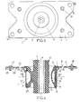
- la figure 4 représente schématiquement en coupe axiale, analogue à celle des figures 1 et 2, le support représenté sur la figure 3 ; et
- la figure 5 représente schématiquement en coupe transversale le support représenté sur les figures 3 et 4.
Claims (6)
- Support antivibratoire hydraulique comprenant:caractérisé par le fait :une armature interne (2) rigide s'étendant longitudinalement le long d'un axe (X),une cage (3) rigide comportant une paroi tubulaire (6) et une collerette (7), la paroi tubulaire (6) s'étendant entre deux extrémités axiales (8,9) et entourant l'armature interne (2), et la collerette (7) s'étendant radialement vers l'extérieur, à partir de la paroi tubulaire (6), à l'une (9) des extrémités axiales (8,9) de celle-ci,une armature externe (5) cylindrique s'étendant également entre deux extrémités axiales, dans laquelle est logée la cage (3) et comportant, à l'une de ses extrémités axiales, un épaulement (21) et un collet (22), l'épaulement (21) délimitant, avec la collerette (7) et la paroi tubulaire (6), un canal (24) étroit s'étendant selon un arc de cercle centré sur l'axe (X), et le collet (22) s'étendant à partir de l'épaulement (21) perpendiculairement à l'axe (X),un corps en élastomère (4), relié à l'armature interne (2) et à la cage (3), tapissant au moins une partie de la surface de la paroi tubulaire (6) et de la collerette (7) en regard de l'armature externe (5), ce corps en élastomère (4) étant conformé pour fermer le canal (24) de manière étanche et pour former avec l'armature externe (5) au moins deux poches (13,14) communiquant entre elles par le canal (24), l'ensemble des poches (13,14) et du canal (24) étant rempli d'un liquide amortisseur (L) et l'une des poches (13,14) étant déformable lorsque l'armature interne (2) et la cage (3) subissent un déplacement radial l'une par rapport à l'autre, etune platine (17), solidaire d'au moins un élément choisi parmi la cage (3) et l'armature externe (5), s'étendant perpendiculairement à l'axe (X) et comportant des moyens de fixation (18) du support (1) sur une pièce extérieure (26) à ce support (1),que le collet (22) s'étend radialement vers l'extérieur à partir de l'épaulement (21) et comporte au moins une portion de surface en regard de la collerette (7), avec une épaisseur de corps en élastomère (4) intercalée entre le collet (22) et la collerette (7),que le collet (22) est directement fixé à la collerette (7) par sertissage,et qu'au moins l'un des éléments choisis parmi le collet (22) et la collerette (7) constitue la platine (17).
- Support selon la revendication 1, dans lequel l'un des éléments parmi le collet (22) et la collerette (7) comporte au moins un orifice de sertissage (19) avec une fraisure formant une retenue pour une sertissure (25) venue de matière avec l'autre de ces éléments.
- Support selon l'une des revendications précédentes dans lequel la platine (17) est constituée par la collerette (7) et s'étend dans un plan sensiblement perpendiculaire à l'axe (X).
- Support selon l'une des revendications précédentes, dans lequel l'armature externe (5) est réalisée dans une matière choisie parmi l'aluminium, l'acier et une matière plastique.
- Support selon l'une des revendications précédentes, dans lequel l'épaulement (21) est réalisé par emboutissage de l'armature externe (5).
- Support selon l'une des revendications 1 à 4, dans lequel l'épaulement (21) est réalisé par moulage de l'armature externe (5).
Applications Claiming Priority (2)
| Application Number | Priority Date | Filing Date | Title |
|---|---|---|---|
| FR0201219A FR2835582B1 (fr) | 2002-02-01 | 2002-02-01 | Support antivibratoire hydraulique |
| FR0201219 | 2002-02-01 |
Publications (2)
| Publication Number | Publication Date |
|---|---|
| EP1333191A1 true EP1333191A1 (fr) | 2003-08-06 |
| EP1333191B1 EP1333191B1 (fr) | 2005-08-24 |
Family
ID=8871445
Family Applications (1)
| Application Number | Title | Priority Date | Filing Date |
|---|---|---|---|
| EP03290192A Expired - Lifetime EP1333191B1 (fr) | 2002-02-01 | 2003-01-24 | Support antivibratoire hydraulique |
Country Status (5)
| Country | Link |
|---|---|
| US (1) | US6702264B2 (fr) |
| EP (1) | EP1333191B1 (fr) |
| DE (1) | DE60301356T2 (fr) |
| ES (1) | ES2248710T3 (fr) |
| FR (1) | FR2835582B1 (fr) |
Cited By (2)
| Publication number | Priority date | Publication date | Assignee | Title |
|---|---|---|---|---|
| US6702264B2 (en) * | 2002-02-01 | 2004-03-09 | Hutchinson | Hydraulic antivibration mounting |
| WO2011035779A1 (fr) * | 2009-09-24 | 2011-03-31 | Zf Friedrichshafen Ag | Palier à douille élastomérique comprenant un tube externe en plastique |
Citations (2)
| Publication number | Priority date | Publication date | Assignee | Title |
|---|---|---|---|---|
| US5711513A (en) * | 1995-01-04 | 1998-01-27 | Hutchinson | Hydraulic antivibration support sleeves |
| US6022006A (en) * | 1997-08-01 | 2000-02-08 | Hutchinson | Hydraulic antivibration support |
Family Cites Families (1)
| Publication number | Priority date | Publication date | Assignee | Title |
|---|---|---|---|---|
| FR2835582B1 (fr) * | 2002-02-01 | 2004-04-09 | Hutchinson | Support antivibratoire hydraulique |
-
2002
- 2002-02-01 FR FR0201219A patent/FR2835582B1/fr not_active Expired - Fee Related
-
2003
- 2003-01-24 ES ES03290192T patent/ES2248710T3/es not_active Expired - Lifetime
- 2003-01-24 DE DE60301356T patent/DE60301356T2/de not_active Expired - Fee Related
- 2003-01-24 EP EP03290192A patent/EP1333191B1/fr not_active Expired - Lifetime
- 2003-01-29 US US10/353,408 patent/US6702264B2/en not_active Expired - Fee Related
Patent Citations (2)
| Publication number | Priority date | Publication date | Assignee | Title |
|---|---|---|---|---|
| US5711513A (en) * | 1995-01-04 | 1998-01-27 | Hutchinson | Hydraulic antivibration support sleeves |
| US6022006A (en) * | 1997-08-01 | 2000-02-08 | Hutchinson | Hydraulic antivibration support |
Cited By (2)
| Publication number | Priority date | Publication date | Assignee | Title |
|---|---|---|---|---|
| US6702264B2 (en) * | 2002-02-01 | 2004-03-09 | Hutchinson | Hydraulic antivibration mounting |
| WO2011035779A1 (fr) * | 2009-09-24 | 2011-03-31 | Zf Friedrichshafen Ag | Palier à douille élastomérique comprenant un tube externe en plastique |
Also Published As
| Publication number | Publication date |
|---|---|
| US20030146555A1 (en) | 2003-08-07 |
| DE60301356T2 (de) | 2006-06-29 |
| ES2248710T3 (es) | 2006-03-16 |
| FR2835582B1 (fr) | 2004-04-09 |
| US6702264B2 (en) | 2004-03-09 |
| FR2835582A1 (fr) | 2003-08-08 |
| EP1333191B1 (fr) | 2005-08-24 |
| DE60301356D1 (de) | 2005-09-29 |
Similar Documents
| Publication | Publication Date | Title |
|---|---|---|
| EP1179688B1 (fr) | Manchon anti-vibratoire hydraulique | |
| FR2830911A1 (fr) | Articulation hydroelastique rotulee | |
| FR2812362A1 (fr) | Support antivibratoire hydraulique et son procede de fabrication | |
| EP0721071B1 (fr) | Perfectionnements aux manchons de support antivibratoires hydrauliques | |
| EP0818639B1 (fr) | Dispositif antivibratoire hydraulique | |
| EP0287455B1 (fr) | Support hydroélastique, notamment pour la suspension d'un moteur de véhicule | |
| WO2020016347A1 (fr) | Butée de suspension de véhicule automobile | |
| BE1007986A5 (fr) | Support elastique en caoutchouc, a amortissement hydraulique. | |
| EP1333191B1 (fr) | Support antivibratoire hydraulique | |
| EP2282076B1 (fr) | Dispositif de liaison antivibratoire pour véhicule et véhicule comportant un tel dispositif | |
| EP0800017B1 (fr) | Support antivibratoire hydraulique et sous-ensemble de véhicule automobile comportant un tel support | |
| FR2851312A1 (fr) | Support antivibratoire hydraulique | |
| EP1645773B1 (fr) | Dispositif antivibratoire hydraulique pour véhicule et procédé de fabrication d'un tel dispositif | |
| EP0429362A1 (fr) | Perfectionnements apportés aux manchons antivibratoires hydrauliques | |
| EP0894995A1 (fr) | Support antivibratoire hydraulique | |
| FR2727179A1 (fr) | Perfectionnements aux supports antivibratoires hydrauliques | |
| FR2807130A1 (fr) | Tube de protection pour unite a piston et cylindre | |
| FR2882413A1 (fr) | Unite a piston-et-cylindre comportant un tube de protection | |
| EP0905405B1 (fr) | Articulation élastique, notamment pour un train roulant de véhicule automobile | |
| EP1443239B1 (fr) | Articulation antivibratoire hydraulique à butées axiales, véhicule équipé d'un telle articulation, et procédé de fabrication d'un telle articulation | |
| EP1378682A1 (fr) | Dispositif d'articulation hydroélastique à effet axial | |
| FR3111332A1 (fr) | Mât d’aéronef comportant au moins un joint d’étanchéité intercalé entre une structure fixe et un panneau démontable d’un carénage | |
| FR2788822A1 (fr) | Support antivibratoire hydraulique, train de roulement equipe d'un tel support, et procede de fabrication d'un tel support | |
| EP0442764B1 (fr) | Articulation hydroélastique à double effet à armatures concentriques | |
| EP0957286A1 (fr) | Support hydroélastique interposé entre un groupe motopropulseur et une caisse d'un véhicule automobile |
Legal Events
| Date | Code | Title | Description |
|---|---|---|---|
| PUAI | Public reference made under article 153(3) epc to a published international application that has entered the european phase |
Free format text: ORIGINAL CODE: 0009012 |
|
| AK | Designated contracting states |
Designated state(s): AT BE BG CH CY CZ DE DK EE ES FI FR GB GR HU IE IT LI LU MC NL PT SE SI SK TR |
|
| AX | Request for extension of the european patent |
Extension state: AL LT LV MK RO |
|
| 17P | Request for examination filed |
Effective date: 20030705 |
|
| AKX | Designation fees paid |
Designated state(s): DE ES FR GB IT |
|
| GRAP | Despatch of communication of intention to grant a patent |
Free format text: ORIGINAL CODE: EPIDOSNIGR1 |
|
| GRAS | Grant fee paid |
Free format text: ORIGINAL CODE: EPIDOSNIGR3 |
|
| GRAA | (expected) grant |
Free format text: ORIGINAL CODE: 0009210 |
|
| AK | Designated contracting states |
Kind code of ref document: B1 Designated state(s): DE ES FR GB IT |
|
| PG25 | Lapsed in a contracting state [announced via postgrant information from national office to epo] |
Ref country code: GB Free format text: LAPSE BECAUSE OF FAILURE TO SUBMIT A TRANSLATION OF THE DESCRIPTION OR TO PAY THE FEE WITHIN THE PRESCRIBED TIME-LIMIT Effective date: 20050824 |
|
| REG | Reference to a national code |
Ref country code: GB Ref legal event code: FG4D Free format text: NOT ENGLISH |
|
| REF | Corresponds to: |
Ref document number: 60301356 Country of ref document: DE Date of ref document: 20050929 Kind code of ref document: P |
|
| REG | Reference to a national code |
Ref country code: ES Ref legal event code: FG2A Ref document number: 2248710 Country of ref document: ES Kind code of ref document: T3 |
|
| GBV | Gb: ep patent (uk) treated as always having been void in accordance with gb section 77(7)/1977 [no translation filed] |
Effective date: 20050824 |
|
| PLBE | No opposition filed within time limit |
Free format text: ORIGINAL CODE: 0009261 |
|
| STAA | Information on the status of an ep patent application or granted ep patent |
Free format text: STATUS: NO OPPOSITION FILED WITHIN TIME LIMIT |
|
| 26N | No opposition filed |
Effective date: 20060526 |
|
| PGFP | Annual fee paid to national office [announced via postgrant information from national office to epo] |
Ref country code: ES Payment date: 20080125 Year of fee payment: 6 |
|
| PGFP | Annual fee paid to national office [announced via postgrant information from national office to epo] |
Ref country code: DE Payment date: 20080110 Year of fee payment: 6 Ref country code: IT Payment date: 20080124 Year of fee payment: 6 |
|
| PGFP | Annual fee paid to national office [announced via postgrant information from national office to epo] |
Ref country code: FR Payment date: 20080205 Year of fee payment: 6 |
|
| PG25 | Lapsed in a contracting state [announced via postgrant information from national office to epo] |
Ref country code: DE Free format text: LAPSE BECAUSE OF NON-PAYMENT OF DUE FEES Effective date: 20090801 |
|
| REG | Reference to a national code |
Ref country code: FR Ref legal event code: ST Effective date: 20091030 |
|
| REG | Reference to a national code |
Ref country code: ES Ref legal event code: FD2A Effective date: 20090126 |
|
| PG25 | Lapsed in a contracting state [announced via postgrant information from national office to epo] |
Ref country code: FR Free format text: LAPSE BECAUSE OF NON-PAYMENT OF DUE FEES Effective date: 20090202 Ref country code: ES Free format text: LAPSE BECAUSE OF NON-PAYMENT OF DUE FEES Effective date: 20090126 |
|
| PG25 | Lapsed in a contracting state [announced via postgrant information from national office to epo] |
Ref country code: IT Free format text: LAPSE BECAUSE OF NON-PAYMENT OF DUE FEES Effective date: 20090124 |