EP1333230A2 - Türverriegelung für ein Haushaltgerät - Google Patents
Türverriegelung für ein Haushaltgerät Download PDFInfo
- Publication number
- EP1333230A2 EP1333230A2 EP03000238A EP03000238A EP1333230A2 EP 1333230 A2 EP1333230 A2 EP 1333230A2 EP 03000238 A EP03000238 A EP 03000238A EP 03000238 A EP03000238 A EP 03000238A EP 1333230 A2 EP1333230 A2 EP 1333230A2
- Authority
- EP
- European Patent Office
- Prior art keywords
- door
- door lock
- force
- hook
- stop
- Prior art date
- Legal status (The legal status is an assumption and is not a legal conclusion. Google has not performed a legal analysis and makes no representation as to the accuracy of the status listed.)
- Granted
Links
- 239000002184 metal Substances 0.000 claims abstract description 7
- 238000011161 development Methods 0.000 description 5
- 230000018109 developmental process Effects 0.000 description 5
- 238000004519 manufacturing process Methods 0.000 description 5
- 230000006378 damage Effects 0.000 description 4
- 239000003795 chemical substances by application Substances 0.000 description 3
- 239000000463 material Substances 0.000 description 3
- 238000002347 injection Methods 0.000 description 2
- 239000007924 injection Substances 0.000 description 2
- 239000000243 solution Substances 0.000 description 2
- 238000004140 cleaning Methods 0.000 description 1
- 230000001771 impaired effect Effects 0.000 description 1
- 238000001746 injection moulding Methods 0.000 description 1
- 238000000034 method Methods 0.000 description 1
- 238000003860 storage Methods 0.000 description 1
Images


Classifications
-
- E—FIXED CONSTRUCTIONS
- E05—LOCKS; KEYS; WINDOW OR DOOR FITTINGS; SAFES
- E05B—LOCKS; ACCESSORIES THEREFOR; HANDCUFFS
- E05B15/00—Other details of locks; Parts for engagement by bolts of fastening devices
- E05B15/10—Bolts of locks or night latches
- E05B15/102—Bolts having movable elements
-
- E—FIXED CONSTRUCTIONS
- E05—LOCKS; KEYS; WINDOW OR DOOR FITTINGS; SAFES
- E05B—LOCKS; ACCESSORIES THEREFOR; HANDCUFFS
- E05B15/00—Other details of locks; Parts for engagement by bolts of fastening devices
- E05B15/10—Bolts of locks or night latches
- E05B15/101—Spring-retracted bolts
-
- E—FIXED CONSTRUCTIONS
- E05—LOCKS; KEYS; WINDOW OR DOOR FITTINGS; SAFES
- E05B—LOCKS; ACCESSORIES THEREFOR; HANDCUFFS
- E05B47/00—Operating or controlling locks or other fastening devices by electric or magnetic means
- E05B47/06—Controlling mechanically-operated bolts by electro-magnetically-operated detents
- E05B47/0603—Controlling mechanically-operated bolts by electro-magnetically-operated detents the detent moving rectilinearly
-
- E—FIXED CONSTRUCTIONS
- E05—LOCKS; KEYS; WINDOW OR DOOR FITTINGS; SAFES
- E05C—BOLTS OR FASTENING DEVICES FOR WINGS, SPECIALLY FOR DOORS OR WINDOWS
- E05C3/00—Fastening devices with bolts moving pivotally or rotatively
- E05C3/02—Fastening devices with bolts moving pivotally or rotatively without latching action
-
- F—MECHANICAL ENGINEERING; LIGHTING; HEATING; WEAPONS; BLASTING
- F24—HEATING; RANGES; VENTILATING
- F24C—DOMESTIC STOVES OR RANGES ; DETAILS OF DOMESTIC STOVES OR RANGES, OF GENERAL APPLICATION
- F24C15/00—Details
- F24C15/02—Doors specially adapted for stoves or ranges
- F24C15/022—Latches
-
- E—FIXED CONSTRUCTIONS
- E05—LOCKS; KEYS; WINDOW OR DOOR FITTINGS; SAFES
- E05B—LOCKS; ACCESSORIES THEREFOR; HANDCUFFS
- E05B15/00—Other details of locks; Parts for engagement by bolts of fastening devices
- E05B15/04—Spring arrangements in locks
-
- E—FIXED CONSTRUCTIONS
- E05—LOCKS; KEYS; WINDOW OR DOOR FITTINGS; SAFES
- E05B—LOCKS; ACCESSORIES THEREFOR; HANDCUFFS
- E05B17/00—Accessories in connection with locks
- E05B17/20—Means independent of the locking mechanism for preventing unauthorised opening, e.g. for securing the bolt in the fastening position
- E05B17/2007—Securing, deadlocking or "dogging" the bolt in the fastening position
- E05B17/203—Securing, deadlocking or "dogging" the bolt in the fastening position not following the movement of the bolt
- E05B17/2038—Securing, deadlocking or "dogging" the bolt in the fastening position not following the movement of the bolt moving rectilinearly
Definitions
- the invention relates to a door lock of the type mentioned in the preamble of claim 1.
- a door lock of the type in question is, for example, from the order catalog "Electromechanical switching, protection and control devices 2000", pages 253 and 254, from the company E-T-A Elektrotechnische Apparate GmbH, 90518 Altdorf.
- the one described there Locking system with the number 6140 points one in a closed position Inclusion of a door engaging hook as a locking block, the Locking system in the installed state, for example on a body and the Recording is arranged as a lock latch on the door of a household appliance.
- the catch is rotatably supported on the rest of the locking system and is with the door open in an open position. Furthermore, a projection is formed as a stop on the hook.
- a disadvantage of the known Door lock is that its functioning due to tolerances of the relative location of Locking system and recording is impaired or impossible. Tolerances can for example due to manufacturing or assembly-related deviations in dimensions of the door and / or body of the household appliance or of the locking system and holder are caused. Larger tolerances can also damage the Lock the door until it is completely unusable.
- the invention thus presents the problem of creating a door lock, its function even with unusually large tolerances of the dimensions and / or the spatial arrangement the components used is guaranteed.
- a door lock with tolerance compensation is already from DE 197 38 508 C1 known.
- the subject of this document is to lock a muffle door on this a locking bolt is provided as a locking block, which in a means of a Carrier device attached to the body of the furnace as a lock latch can be introduced.
- the locking bolt is from the Recording facility blocked or released.
- Receiving device movably arranged on the carrier device.
- a disadvantage of this The solution is that the moving mass is large because the entire receiving device is relative to the Carrier device is moved.
- the components of the door lock such as the spring element for Compensation of the forces acting on the receiving device, taking into account the to interpret the movement of large mass forces, which are components with large Dimensions and / or the use of high quality materials required.
- this tolerance compensation in which the entire receiving device is movable is a larger space requirement for the door lock.
- the door lock it is possible to design the door lock to be suitable for a pull-open door.
- a advantageous development of the teaching according to the invention provides that the Locking block can be secured in the closed position by a second force-generating means. In this way, a secure locking of the door is ensured, which is especially for Household appliances with a high risk potential, such as stoves or ovens with pyrolytic self-cleaning is required.
- the second force-generating means is a pin which can be engaged in a recess in the locking block.
- the second force-generating agent is particularly simple and inexpensive realized.
- the first force-generating means is a spring, which has one free end on the locking block and is attached to a rest of the household appliance with its other free end.
- the first force-generating agent is easy and inexpensive to produce, because springs Standard components are.
- the type, material and size of the spring is the first force-generating agent in a wide range Limits selectable.
- the spring is expediently a helical spring.
- the Stop is a leg spring.
- the door lock is particularly simple Formable with tolerance compensation.
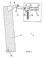
- FIG. 1 shows a first exemplary embodiment of a door lock 2 according to the invention shown.
- the door lock 2 is part of a part and purely schematically illustrated cooker that a door 4 with a receptacle 6 as Has lock latch and a body with a hook 8 as a locking block.
- the door 4 is over a hinge 10 connected to the body, so that the door 4 in a closed state covers the baking muffle opening and closes the baking muffle of the cooker.
- the hook 8 is held rotatably on the body via a pin 12 parallel to the plane of the sheet.
- a Leg spring 14 is a resilient stop with one leg on which the Door 4 facing arm of the hook 8 held.
- the other leg of the leg spring 14 extends as a stop substantially in the same direction as that at the free end of the arm facing the door 4 formed projection and projects in this direction over the A head start.
- On the opposite arm of the hook 8 is a free with her End of a coil spring 16 held as the first force-generating means, the other free end is held on the body.
- the coil spring 16 is biased to train, so that this promotes the rotation of the hook 8 clockwise.
- the rotation of the hook 8 in Clockwise is limited by a pin 18 as a stop for the hook 8.
- a recess 20 is provided in the same arm, in which a merely schematic shown bolt 22 can be engaged.
- the pin 22 is also schematic along one shown guide 24 between an unlocked position and a locked position movable back and forth, the bolt 22 in the locking position in the recess 20th engages and thus sets the hook 8 in a closed position.
- the bolt 22 and the Guide 24 therefore cooperate as a second force-generating means.
- FIG. 1 shows the door lock 2 according to the invention in one Open position of the hook 8, in which the door 4 does not close the muffle of the cooker.
- the hook 8 lies, promoted by the restoring force of the coil spring 16, with that of the door 4 facing arm on the pin 18.
- the leg spring 14 is relaxed and the hook 8 is not in engagement with the receptacle 6 of the door 4.
- the bolt 22 is in the Unlocked.
- the hook 8 is located at the moment when the door 4 is closed in FIG. 2 not yet in engagement with the receptacle 6 of the door 4, which is designed as a stop Leg of the leg spring 14 just touched. Will the door 4 continue towards the Body of the cooker moves, so the hook 8 is counterclockwise around the peg 12 rotated. The coil spring 16 is further tensioned and the hook 8 lies with the arm facing away from the door 4 no longer on the pin 18. The leg spring 14 is largely relaxed.
- the door 4 lies against the body of the cooker, see Fig. 3.
- the Hook 8 engages with the projection in the receptacle 6 of the door 4.
- the compressive force of the door 4 can, for example, on another Body and door 4 held and generated between these acting spring.
- Fig. 3 the recess 20 and the are in its unlocked position Bolt 22 shown opposite, so that the bolt 22 along the guide 24 in his Locking position in which the bolt 22 engages in the recess 20 is movable.
- Fig. 4 shows the arrangement of Fig. 3 in plan view.
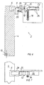
- FIG. 6 and 7 is a second embodiment of an inventive Door lock shown with door 4 closed.
- Stop on a trained on the hook 8 and extending along the hook 8 Guide 25 sliding carriage 26 used.
- the movement of the carriage 26 in the direction of Door 4 is in the region of the end of the guide 25 facing the door 4 by one on the Hook 8 formed further projection limited.
- a bearing spring preloaded under pressure 28 is at one free end of the carriage 26 and at the other free end a shoulder formed on the hook 8.
- the carriage 26 by the restoring force Bearing spring 28 pressed against the further projection formed on the hook 8. In the event of of the overturning of the door 4, this becomes analogous to the first exemplary embodiment along the guide 25 and against the restoring force of the bearing spring 28 away from the door 4 moving carriage 26 compensated.
- a third embodiment is shown in FIG. 8.
- Stop a lever 30 rotatable about a pin 29 formed on the hook 8.
- the lever 30 has a longer arm as a stop for the door 4 and a shorter arm.
- a bearing spring 28 is similar to the previous embodiment with the same a free end on the longer arm of the lever 30 and the other free end a shoulder formed on the hook 8.
- the movement of the longer arm of the Lever 30 is in the direction of the door 4 by a further projection formed on the hook 8 limited, which forms the counter bearing for the shorter arm of the lever 30.
- normal case is the shorter arm of the Lever 30 by the restoring force of the bearing spring 28 against that formed on the hook 8 further lead pressed. In the event of door 4 being overturned, this becomes analogous to that previous embodiments, through which the pin 29 against the Turn clockwise and against the restoring force of the bearing spring 28 away from the door 4 longer arm of the lever 30 compensated.
- a first leg is a stop resilient metal strip 32 partially in the manufacture of the hook 8 with plastic overmoulded or injection molded and in this way permanently connected to the hook 8.
- the hook 8 is formed as a plastic injection molding, during its manufacture Metal strip 32 has been inserted into the injection mold. Which is essentially vertical to the longitudinal extent of the hook 8 extending second leg is a stop for the Door 4 trained.
- the door 4 is on the second leg of the metal strip 32, the second leg of the metal strip 32 is essentially relaxed.
- the second leg of the Metal strip 32 analogous to the previous embodiments, stretched and the Overstroke compensated.
- the above-mentioned exemplary embodiments guarantee even with unusually large tolerances the dimensions of the components and their relative position to one another the function of Door lock according to the invention 2. Furthermore, damage or destruction of the Tolerance compensation or the door lock 2 due to unusually large tolerances prevented.
- the first and fourth exemplary embodiments show in particular simple and therefore inexpensive possibilities of the door lock 2 according to the invention.
Landscapes
- Engineering & Computer Science (AREA)
- Mechanical Engineering (AREA)
- Chemical & Material Sciences (AREA)
- Combustion & Propulsion (AREA)
- General Engineering & Computer Science (AREA)
- Electric Ovens (AREA)
- Lock And Its Accessories (AREA)
- Cookers (AREA)
- Washing And Drying Of Tableware (AREA)
Abstract
Description
- Figur 1
- eine teilweise geschnittene Seitenansicht eines ersten Ausführungsbeispiels einer erfindungsgemäßen Türverriegelung bei geöffneter Tür,
- Figur 2
- eine teilweise geschnittene Seitenansicht der Türverriegelung aus Fig. 1 in einer weiteren Lage bei geöffneter Tür,
- Figur 3
- eine teilweise geschnittene Seitenansicht der Türverriegelung aus Fig. 1 bei geschlossener Tür,
- Figur 4
- eine Draufsicht der Türverriegelung aus Fig. 3,
- Figur 5
- eine teilweise geschnittene Seitenansicht der Türverriegelung aus Fig. 1 in einer weiteren Lage bei geschlossener Tür,
- Figur 6
- eine teilweise geschnittene Seitenansicht eines zweiten Ausführungsbeispiels einer erfindungsgemäßen Türverriegelung bei geschlossener Tür,
- Figur 7
- eine Draufsicht der Türverriegelung aus Fig. 6,
- Figur 8
- eine teilweise geschnittene Seitenansicht eines dritten Ausführungsbeispiels einer erfindungsgemäßen Türverriegelung bei geschlossener Tür und
- Figur 9
- eine teilweise geschnittene Seitenansicht eines vierten Ausführungsbeispiels einer erfindungsgemäßen Türverriegelung ebenfalls bei geschlossener Tür.
Claims (7)
- Türverriegelung für ein Haushaltgerät, insbesondere einen Backofen, mit einer Schlossfalle und mit einem Schließkloben, die an sich gegenüberliegenden Bauteilen des Haushaltgeräts gehaltert sind, wobei der drehbar gelagerte Schließkloben durch ein erstes krafterzeugendes Mittel in eine Öffnungsstellung überführbar ist, einen Anschlag für das die Schlossfalle haltende Bauteil aufweist und der Schließkloben mittels des Anschlages gegen die Kraft des ersten krafterzeugenden Mittels in die Schließstellung überführbar ist,
dadurch gekennzeichnet, dass der Anschlag (Schenkelfeder 14; Metallstreifen 32) federnd ausgebildet ist. - Türverriegelung für ein Haushaltgerät, insbesondere einen Backofen, mit einer Schlossfalle und mit einem Schließkloben, die an sich gegenüberliegenden Bauteilen des Haushaltgeräts gehaltert sind, wobei der drehbar gelagerte Schließkloben durch ein erstes krafterzeugendes Mittel in eine Öffnungsstellung überführbar ist, einen Anschlag für das die Schlossfalle haltende Bauteil aufweist und der Schließkloben mittels des Anschlages gegen die Kraft des ersten krafterzeugenden Mittels in die Schließstellung überführbar ist,
dadurch gekennzeichnet, dass die Lagerung (Lagerfeder 28) des Anschlages federnd ausgebildet ist. - Türverriegelung (2) nach Anspruch 1 oder 2,
dadurch gekennzeichnet, dass der Schließkloben (Haken 8) durch ein zweites krafterzeugendes Mittel (Bolzen 22) in der Schließstellung sicherbar ist. - Türverriegelung (2) nach Anspruch 3,
dadurch gekennzeichnet, dass das zweite krafterzeugende Mittel ein in eine Ausnehmung (20) des Schließklobens (Haken 8) eingreifbarer Bolzen (22) ist. - Türverriegelung (2) nach einem der Ansprüche 1 bis 4,
dadurch gekennzeichnet, dass das erste krafterzeugende Mittel eine Feder (Schraubenfeder 16) ist, die mit ihrem einen freien Ende an dem Schließkloben (Haken 8) und mit ihrem anderen freien Ende an einem Rest des Haushaltgeräts (Korpus) gehaltert ist. - Türverriegelung (2) nach Anspruch 5,
dadurch gekennzeichnet, dass die Feder eine Schraubenfeder (16) ist. - Türverriegelung (2) nach einem der Ansprüche 1 bis 6,
dadurch gekennzeichnet, dass der Anschlag eine Schenkelfeder (14) ist.
Applications Claiming Priority (2)
| Application Number | Priority Date | Filing Date | Title |
|---|---|---|---|
| DE10202027 | 2002-01-18 | ||
| DE10202027A DE10202027C1 (de) | 2002-01-18 | 2002-01-18 | Türverriegelung für ein Haushaltgerät |
Publications (3)
| Publication Number | Publication Date |
|---|---|
| EP1333230A2 true EP1333230A2 (de) | 2003-08-06 |
| EP1333230A3 EP1333230A3 (de) | 2004-01-07 |
| EP1333230B1 EP1333230B1 (de) | 2005-07-13 |
Family
ID=7712598
Family Applications (1)
| Application Number | Title | Priority Date | Filing Date |
|---|---|---|---|
| EP03000238A Expired - Lifetime EP1333230B1 (de) | 2002-01-18 | 2003-01-08 | Türverriegelung für ein Haushaltgerät |
Country Status (3)
| Country | Link |
|---|---|
| EP (1) | EP1333230B1 (de) |
| AT (1) | ATE299574T1 (de) |
| DE (2) | DE10202027C1 (de) |
Cited By (7)
| Publication number | Priority date | Publication date | Assignee | Title |
|---|---|---|---|---|
| FR2912493A1 (fr) * | 2007-02-08 | 2008-08-15 | Brandt Ind Sas | Four de cuisson comprenant au moins un dispositif de verrouillage de securite et procede associe |
| ITTO20100891A1 (it) * | 2010-11-08 | 2012-05-09 | Eltek Spa | Dispositivo bloccoporta per elettrodomestici |
| ITTO20100892A1 (it) * | 2010-11-08 | 2012-05-09 | Eltek Spa | Dispositivo bloccoporta per elettrodomestici e meccanismo bistabile |
| US20150035295A1 (en) * | 2013-07-31 | 2015-02-05 | Illinois Tool Works Inc. | Door latch and a dishwasher mounted with the door latch |
| EP3911821A4 (de) * | 2019-01-15 | 2022-04-13 | Dan Raz Ltd. | Plattenverschlussvorrichtung |
| WO2023178730A1 (zh) * | 2022-03-21 | 2023-09-28 | 广东美的厨房电器制造有限公司 | 门锁结构、家用电器及家用电器的控制方法 |
| US12473751B2 (en) | 2022-03-21 | 2025-11-18 | Guangdong Midea Kitchen Appliances Manufacturing Co., Ltd. | Latching structure, household appliance, and control method for household appliance |
Families Citing this family (3)
| Publication number | Priority date | Publication date | Assignee | Title |
|---|---|---|---|---|
| DE102004039431A1 (de) * | 2004-08-13 | 2006-02-23 | BSH Bosch und Siemens Hausgeräte GmbH | Haushaltselektrogerät |
| DE102016013554B4 (de) | 2016-11-12 | 2021-04-08 | Oechsler Ag | Türverriegelung, insbesondere für ein Haushaltsgerät mit hohem Gefährdungspotential |
| CN116517405A (zh) * | 2023-05-31 | 2023-08-01 | 广东美的厨房电器制造有限公司 | 烹饪器具 |
Family Cites Families (3)
| Publication number | Priority date | Publication date | Assignee | Title |
|---|---|---|---|---|
| GB740652A (en) * | 1953-08-08 | 1955-11-16 | Stoves Ltd | Improvements in or relating to doors for cabinets or containers such for example as domestic ovens and refrigerators |
| US5132503A (en) * | 1989-12-30 | 1992-07-21 | Samsung Electronics Co., Ltd. | Apparatus for detecting the open or closed condition of a microwave oven door |
| DE19738508C1 (de) * | 1997-09-03 | 1998-11-12 | Aeg Hausgeraete Gmbh | Vorrichtung zum Verriegeln einer Ofenmuffeltür |
-
2002
- 2002-01-18 DE DE10202027A patent/DE10202027C1/de not_active Expired - Fee Related
-
2003
- 2003-01-08 DE DE50300741T patent/DE50300741D1/de not_active Expired - Lifetime
- 2003-01-08 AT AT03000238T patent/ATE299574T1/de active
- 2003-01-08 EP EP03000238A patent/EP1333230B1/de not_active Expired - Lifetime
Cited By (10)
| Publication number | Priority date | Publication date | Assignee | Title |
|---|---|---|---|---|
| FR2912493A1 (fr) * | 2007-02-08 | 2008-08-15 | Brandt Ind Sas | Four de cuisson comprenant au moins un dispositif de verrouillage de securite et procede associe |
| ITTO20100891A1 (it) * | 2010-11-08 | 2012-05-09 | Eltek Spa | Dispositivo bloccoporta per elettrodomestici |
| ITTO20100892A1 (it) * | 2010-11-08 | 2012-05-09 | Eltek Spa | Dispositivo bloccoporta per elettrodomestici e meccanismo bistabile |
| EP2450510A3 (de) * | 2010-11-08 | 2017-11-22 | Eltek S.p.A. | Türverriegelungsvorrichtung für Haushaltsgerät und bistabiler Mechanismus |
| US20150035295A1 (en) * | 2013-07-31 | 2015-02-05 | Illinois Tool Works Inc. | Door latch and a dishwasher mounted with the door latch |
| US10858859B2 (en) * | 2013-07-31 | 2020-12-08 | Illinois Tool Works Inc. | Door latch and a dishwasher mounted with the door latch |
| EP3911821A4 (de) * | 2019-01-15 | 2022-04-13 | Dan Raz Ltd. | Plattenverschlussvorrichtung |
| US12291892B2 (en) | 2019-01-15 | 2025-05-06 | Dan Raz Ltd. | Panel closure apparatus |
| WO2023178730A1 (zh) * | 2022-03-21 | 2023-09-28 | 广东美的厨房电器制造有限公司 | 门锁结构、家用电器及家用电器的控制方法 |
| US12473751B2 (en) | 2022-03-21 | 2025-11-18 | Guangdong Midea Kitchen Appliances Manufacturing Co., Ltd. | Latching structure, household appliance, and control method for household appliance |
Also Published As
| Publication number | Publication date |
|---|---|
| DE50300741D1 (de) | 2005-08-18 |
| ATE299574T1 (de) | 2005-07-15 |
| EP1333230A3 (de) | 2004-01-07 |
| EP1333230B1 (de) | 2005-07-13 |
| DE10202027C1 (de) | 2003-10-16 |
Similar Documents
| Publication | Publication Date | Title |
|---|---|---|
| DE60109146T2 (de) | Türverriegelungseinrichtung für ein elektrisches haushaltsgerät | |
| DE10202027C1 (de) | Türverriegelung für ein Haushaltgerät | |
| DE102011050053A1 (de) | Scharnier | |
| EP3199736A1 (de) | Anschlagdämpfer | |
| DE102010036636B4 (de) | Faltschloss | |
| DE202008012536U1 (de) | Steuerantrieb für ein Kraftfahrzeugschloß | |
| DE102018120551A1 (de) | Kraftfahrzeugschloss, insbesondere elektrisch betätigbares Kraftfahrzeugschloss | |
| DE102009026142A1 (de) | Rastbeschlag für eine Auszugsführung | |
| EP0821124B1 (de) | Schloss mit einem in einem Schlossgehäuse gelagerten seitlich herausbewegbaren Riegel | |
| DE60025560T2 (de) | Schloss | |
| DE102012015227A1 (de) | Betätigungsvorrichtung für eine an einer Kraftfahrzeugkarosserie gelagerten Abdeckklappe | |
| DE102007029901A1 (de) | Verriegelungsvorrichtung für die Tür eines Haushaltsgeräts, insbesondere einer Haushalt-Geschirrspülmaschine, Geschirrspülmaschine und Verfahren zum Betätigen der Tür eines Haushaltsgeräts | |
| DE202011105510U1 (de) | Türöffner mit Sperr-Riegel | |
| DE19861096A1 (de) | Elektromotorischer Stellantrieb für ein Kraftfahrzeugschloß | |
| EP1682737B1 (de) | Gehäuse- und verschlusselement mit überschlagsicherung | |
| EP4136300B1 (de) | Kraftfahrzeug-schloss, insbesondere kraftfahrzeug-türschloss | |
| DE102007041402A1 (de) | Schloss für eine Schiebetür | |
| DE3425090C1 (de) | Verriegelungsvorrichtung mit wenigstens einem Riegel oder dgl. und mit einer Sperre fuer diesen Riegel | |
| DE3427296A1 (de) | Fachschliessanordnung mit einem ein permutationsschloss aufweisenden verriegelungsapparat | |
| EP3273164B1 (de) | Gargerät mit verriegelungsvorrichtung | |
| DE19846863A1 (de) | Türverriegelungseinrichtung für einen gegen Öffnen zu sichernden Behandlungsraum eines Haushaltsgeräts | |
| DE202015100177U1 (de) | Vorrichtung zum Verhindern des Schließens einer Tür | |
| EP2479363B1 (de) | Verschluss für einen Treibstangenbeschlag | |
| DE3810403C2 (de) | ||
| EP3870785B1 (de) | Kraftfahrzeugschloss, insbesondere kraftfahrzeugtürschloss |
Legal Events
| Date | Code | Title | Description |
|---|---|---|---|
| PUAI | Public reference made under article 153(3) epc to a published international application that has entered the european phase |
Free format text: ORIGINAL CODE: 0009012 |
|
| AK | Designated contracting states |
Designated state(s): AT BE BG CH CY CZ DE DK EE ES FI FR GB GR HU IE IT LI LU MC NL PT SE SI SK TR |
|
| AX | Request for extension of the european patent |
Extension state: AL LT LV MK RO |
|
| PUAL | Search report despatched |
Free format text: ORIGINAL CODE: 0009013 |
|
| AK | Designated contracting states |
Kind code of ref document: A3 Designated state(s): AT BE BG CH CY CZ DE DK EE ES FI FR GB GR HU IE IT LI LU MC NL PT SE SI SK TR |
|
| AX | Request for extension of the european patent |
Extension state: AL LT LV MK RO |
|
| 17P | Request for examination filed |
Effective date: 20040528 |
|
| AKX | Designation fees paid |
Designated state(s): AT BE BG CH CY CZ DE DK EE ES FI FR GB GR HU IE IT LI LU MC NL PT SE SI SK TR |
|
| GRAP | Despatch of communication of intention to grant a patent |
Free format text: ORIGINAL CODE: EPIDOSNIGR1 |
|
| GRAS | Grant fee paid |
Free format text: ORIGINAL CODE: EPIDOSNIGR3 |
|
| GRAA | (expected) grant |
Free format text: ORIGINAL CODE: 0009210 |
|
| AK | Designated contracting states |
Kind code of ref document: B1 Designated state(s): AT BE BG CH CY CZ DE DK EE ES FI FR GB GR HU IE IT LI LU MC NL PT SE SI SK TR |
|
| PG25 | Lapsed in a contracting state [announced via postgrant information from national office to epo] |
Ref country code: TR Free format text: LAPSE BECAUSE OF FAILURE TO SUBMIT A TRANSLATION OF THE DESCRIPTION OR TO PAY THE FEE WITHIN THE PRESCRIBED TIME-LIMIT Effective date: 20050713 Ref country code: IE Free format text: LAPSE BECAUSE OF FAILURE TO SUBMIT A TRANSLATION OF THE DESCRIPTION OR TO PAY THE FEE WITHIN THE PRESCRIBED TIME-LIMIT Effective date: 20050713 Ref country code: SI Free format text: LAPSE BECAUSE OF FAILURE TO SUBMIT A TRANSLATION OF THE DESCRIPTION OR TO PAY THE FEE WITHIN THE PRESCRIBED TIME-LIMIT Effective date: 20050713 Ref country code: FI Free format text: LAPSE BECAUSE OF FAILURE TO SUBMIT A TRANSLATION OF THE DESCRIPTION OR TO PAY THE FEE WITHIN THE PRESCRIBED TIME-LIMIT Effective date: 20050713 Ref country code: SK Free format text: LAPSE BECAUSE OF FAILURE TO SUBMIT A TRANSLATION OF THE DESCRIPTION OR TO PAY THE FEE WITHIN THE PRESCRIBED TIME-LIMIT Effective date: 20050713 Ref country code: EE Free format text: LAPSE BECAUSE OF FAILURE TO SUBMIT A TRANSLATION OF THE DESCRIPTION OR TO PAY THE FEE WITHIN THE PRESCRIBED TIME-LIMIT Effective date: 20050713 Ref country code: CZ Free format text: LAPSE BECAUSE OF FAILURE TO SUBMIT A TRANSLATION OF THE DESCRIPTION OR TO PAY THE FEE WITHIN THE PRESCRIBED TIME-LIMIT Effective date: 20050713 Ref country code: NL Free format text: LAPSE BECAUSE OF FAILURE TO SUBMIT A TRANSLATION OF THE DESCRIPTION OR TO PAY THE FEE WITHIN THE PRESCRIBED TIME-LIMIT Effective date: 20050713 Ref country code: IT Free format text: LAPSE BECAUSE OF FAILURE TO SUBMIT A TRANSLATION OF THE DESCRIPTION OR TO PAY THE FEE WITHIN THE PRESCRIBED TIME-LIMIT;WARNING: LAPSES OF ITALIAN PATENTS WITH EFFECTIVE DATE BEFORE 2007 MAY HAVE OCCURRED AT ANY TIME BEFORE 2007. THE CORRECT EFFECTIVE DATE MAY BE DIFFERENT FROM THE ONE RECORDED. Effective date: 20050713 |
|
| REG | Reference to a national code |
Ref country code: GB Ref legal event code: FG4D Free format text: NOT ENGLISH |
|
| REG | Reference to a national code |
Ref country code: CH Ref legal event code: EP |
|
| REG | Reference to a national code |
Ref country code: IE Ref legal event code: FG4D Free format text: LANGUAGE OF EP DOCUMENT: GERMAN |
|
| REF | Corresponds to: |
Ref document number: 50300741 Country of ref document: DE Date of ref document: 20050818 Kind code of ref document: P |
|
| PG25 | Lapsed in a contracting state [announced via postgrant information from national office to epo] |
Ref country code: SE Free format text: LAPSE BECAUSE OF FAILURE TO SUBMIT A TRANSLATION OF THE DESCRIPTION OR TO PAY THE FEE WITHIN THE PRESCRIBED TIME-LIMIT Effective date: 20051013 Ref country code: DK Free format text: LAPSE BECAUSE OF FAILURE TO SUBMIT A TRANSLATION OF THE DESCRIPTION OR TO PAY THE FEE WITHIN THE PRESCRIBED TIME-LIMIT Effective date: 20051013 Ref country code: BG Free format text: LAPSE BECAUSE OF FAILURE TO SUBMIT A TRANSLATION OF THE DESCRIPTION OR TO PAY THE FEE WITHIN THE PRESCRIBED TIME-LIMIT Effective date: 20051013 Ref country code: GR Free format text: LAPSE BECAUSE OF FAILURE TO SUBMIT A TRANSLATION OF THE DESCRIPTION OR TO PAY THE FEE WITHIN THE PRESCRIBED TIME-LIMIT Effective date: 20051013 |
|
| PG25 | Lapsed in a contracting state [announced via postgrant information from national office to epo] |
Ref country code: ES Free format text: LAPSE BECAUSE OF FAILURE TO SUBMIT A TRANSLATION OF THE DESCRIPTION OR TO PAY THE FEE WITHIN THE PRESCRIBED TIME-LIMIT Effective date: 20051024 |
|
| GBT | Gb: translation of ep patent filed (gb section 77(6)(a)/1977) |
Effective date: 20051012 |
|
| PG25 | Lapsed in a contracting state [announced via postgrant information from national office to epo] |
Ref country code: PT Free format text: LAPSE BECAUSE OF FAILURE TO SUBMIT A TRANSLATION OF THE DESCRIPTION OR TO PAY THE FEE WITHIN THE PRESCRIBED TIME-LIMIT Effective date: 20051219 |
|
| NLV1 | Nl: lapsed or annulled due to failure to fulfill the requirements of art. 29p and 29m of the patents act | ||
| PG25 | Lapsed in a contracting state [announced via postgrant information from national office to epo] |
Ref country code: HU Free format text: LAPSE BECAUSE OF FAILURE TO SUBMIT A TRANSLATION OF THE DESCRIPTION OR TO PAY THE FEE WITHIN THE PRESCRIBED TIME-LIMIT Effective date: 20060114 |
|
| PG25 | Lapsed in a contracting state [announced via postgrant information from national office to epo] |
Ref country code: LU Free format text: LAPSE BECAUSE OF NON-PAYMENT OF DUE FEES Effective date: 20060131 Ref country code: MC Free format text: LAPSE BECAUSE OF NON-PAYMENT OF DUE FEES Effective date: 20060131 Ref country code: BE Free format text: LAPSE BECAUSE OF NON-PAYMENT OF DUE FEES Effective date: 20060131 |
|
| REG | Reference to a national code |
Ref country code: IE Ref legal event code: FD4D |
|
| ET | Fr: translation filed | ||
| PLBE | No opposition filed within time limit |
Free format text: ORIGINAL CODE: 0009261 |
|
| STAA | Information on the status of an ep patent application or granted ep patent |
Free format text: STATUS: NO OPPOSITION FILED WITHIN TIME LIMIT |
|
| 26N | No opposition filed |
Effective date: 20060418 |
|
| PG25 | Lapsed in a contracting state [announced via postgrant information from national office to epo] |
Ref country code: CH Free format text: LAPSE BECAUSE OF NON-PAYMENT OF DUE FEES Effective date: 20070131 Ref country code: LI Free format text: LAPSE BECAUSE OF NON-PAYMENT OF DUE FEES Effective date: 20070131 |
|
| REG | Reference to a national code |
Ref country code: CH Ref legal event code: PL |
|
| BERE | Be: lapsed |
Owner name: MIELE & CIE. K.G. Effective date: 20060131 |
|
| PG25 | Lapsed in a contracting state [announced via postgrant information from national office to epo] |
Ref country code: CY Free format text: LAPSE BECAUSE OF FAILURE TO SUBMIT A TRANSLATION OF THE DESCRIPTION OR TO PAY THE FEE WITHIN THE PRESCRIBED TIME-LIMIT Effective date: 20050713 |
|
| REG | Reference to a national code |
Ref country code: DE Ref legal event code: R084 Ref document number: 50300741 Country of ref document: DE Effective date: 20121114 |
|
| PGFP | Annual fee paid to national office [announced via postgrant information from national office to epo] |
Ref country code: FR Payment date: 20130207 Year of fee payment: 11 Ref country code: DE Payment date: 20130116 Year of fee payment: 11 Ref country code: GB Payment date: 20130122 Year of fee payment: 11 |
|
| PGFP | Annual fee paid to national office [announced via postgrant information from national office to epo] |
Ref country code: AT Payment date: 20130121 Year of fee payment: 11 |
|
| REG | Reference to a national code |
Ref country code: DE Ref legal event code: R119 Ref document number: 50300741 Country of ref document: DE |
|
| REG | Reference to a national code |
Ref country code: AT Ref legal event code: MM01 Ref document number: 299574 Country of ref document: AT Kind code of ref document: T Effective date: 20140108 |
|
| GBPC | Gb: european patent ceased through non-payment of renewal fee |
Effective date: 20140108 |
|
| REG | Reference to a national code |
Ref country code: DE Ref legal event code: R119 Ref document number: 50300741 Country of ref document: DE Effective date: 20140801 |
|
| PG25 | Lapsed in a contracting state [announced via postgrant information from national office to epo] |
Ref country code: DE Free format text: LAPSE BECAUSE OF NON-PAYMENT OF DUE FEES Effective date: 20140801 |
|
| REG | Reference to a national code |
Ref country code: FR Ref legal event code: ST Effective date: 20140930 |
|
| PG25 | Lapsed in a contracting state [announced via postgrant information from national office to epo] |
Ref country code: GB Free format text: LAPSE BECAUSE OF NON-PAYMENT OF DUE FEES Effective date: 20140108 Ref country code: FR Free format text: LAPSE BECAUSE OF NON-PAYMENT OF DUE FEES Effective date: 20140131 Ref country code: AT Free format text: LAPSE BECAUSE OF NON-PAYMENT OF DUE FEES Effective date: 20140108 |