EP1333287B1 - Méthode et appareil pour modifier la pression dans un dispenseur de fluide - Google Patents
Méthode et appareil pour modifier la pression dans un dispenseur de fluide Download PDFInfo
- Publication number
- EP1333287B1 EP1333287B1 EP03000532A EP03000532A EP1333287B1 EP 1333287 B1 EP1333287 B1 EP 1333287B1 EP 03000532 A EP03000532 A EP 03000532A EP 03000532 A EP03000532 A EP 03000532A EP 1333287 B1 EP1333287 B1 EP 1333287B1
- Authority
- EP
- European Patent Office
- Prior art keywords
- fluid dispenser
- cap
- vent
- valve
- fluid
- Prior art date
- Legal status (The legal status is an assumption and is not a legal conclusion. Google has not performed a legal analysis and makes no representation as to the accuracy of the status listed.)
- Expired - Lifetime
Links
Images








Classifications
-
- G—PHYSICS
- G01—MEASURING; TESTING
- G01N—INVESTIGATING OR ANALYSING MATERIALS BY DETERMINING THEIR CHEMICAL OR PHYSICAL PROPERTIES
- G01N35/00—Automatic analysis not limited to methods or materials provided for in any single one of groups G01N1/00 - G01N33/00; Handling materials therefor
- G01N35/10—Devices for transferring samples or any liquids to, in, or from, the analysis apparatus, e.g. suction devices, injection devices
- G01N35/1009—Characterised by arrangements for controlling the aspiration or dispense of liquids
- G01N35/1016—Control of the volume dispensed or introduced
-
- G—PHYSICS
- G01—MEASURING; TESTING
- G01N—INVESTIGATING OR ANALYSING MATERIALS BY DETERMINING THEIR CHEMICAL OR PHYSICAL PROPERTIES
- G01N1/00—Sampling; Preparing specimens for investigation
- G01N1/28—Preparing specimens for investigation including physical details of (bio-)chemical methods covered elsewhere, e.g. G01N33/50, C12Q
- G01N1/30—Staining; Impregnating ; Fixation; Dehydration; Multistep processes for preparing samples of tissue, cell or nucleic acid material and the like for analysis
- G01N1/31—Apparatus therefor
- G01N1/312—Apparatus therefor for samples mounted on planar substrates
-
- G—PHYSICS
- G01—MEASURING; TESTING
- G01N—INVESTIGATING OR ANALYSING MATERIALS BY DETERMINING THEIR CHEMICAL OR PHYSICAL PROPERTIES
- G01N35/00—Automatic analysis not limited to methods or materials provided for in any single one of groups G01N1/00 - G01N33/00; Handling materials therefor
- G01N35/10—Devices for transferring samples or any liquids to, in, or from, the analysis apparatus, e.g. suction devices, injection devices
- G01N35/1002—Reagent dispensers
-
- G—PHYSICS
- G01—MEASURING; TESTING
- G01N—INVESTIGATING OR ANALYSING MATERIALS BY DETERMINING THEIR CHEMICAL OR PHYSICAL PROPERTIES
- G01N1/00—Sampling; Preparing specimens for investigation
- G01N1/28—Preparing specimens for investigation including physical details of (bio-)chemical methods covered elsewhere, e.g. G01N33/50, C12Q
- G01N1/30—Staining; Impregnating ; Fixation; Dehydration; Multistep processes for preparing samples of tissue, cell or nucleic acid material and the like for analysis
- G01N1/31—Apparatus therefor
- G01N2001/317—Apparatus therefor spraying liquids onto surfaces
-
- G—PHYSICS
- G01—MEASURING; TESTING
- G01N—INVESTIGATING OR ANALYSING MATERIALS BY DETERMINING THEIR CHEMICAL OR PHYSICAL PROPERTIES
- G01N35/00—Automatic analysis not limited to methods or materials provided for in any single one of groups G01N1/00 - G01N33/00; Handling materials therefor
- G01N35/10—Devices for transferring samples or any liquids to, in, or from, the analysis apparatus, e.g. suction devices, injection devices
- G01N2035/1027—General features of the devices
- G01N2035/1034—Transferring microquantities of liquid
Definitions
- a fluid dispenser for an automated biological reaction system has a barrel having a reservoir chamber and a piston, the piston being adjacent to the reservoir chamber.
- the fluid dispenser also has an extension piece connected to the piston.
- the fluid dispenser has a coupler, wherein the coupler has a dispense chamber. The dispense chamber is adjacent to the reservoir chamber. Further, the extension piece moves inside the coupler.
- Previous liquid dispensers had a side by side arrangement whereby the reservoir chamber was to the side of the dispense chamber. In this configuration, the reservoir chamber was smaller and therefore held less fluid. In the present invention the reservoir chamber can be enlarged thereby holding more fluid. For example, in previous dispensers, the reservoir chamber could hold approximately 27.5 mL of fluid whereas, in the present invention, the reservoir chamber can hold approximately 34.0 mL of fluid. Ordinarily, a single dispenser is rated to give 250 shots (i.e., 250 dispenses of fluid). In order to provide the 250 shots in the previous dispensers, different types of couplers, depending on different types of reagents had to be made.
- the reservoir chamber 410 shape is as shown in FIGS. 1A and 1B.
- the reservoir shape may also be funnel-like or any other shape which drains the fluid through the connecting means between the reservoir chamber 410 and the dispense chamber 412.
- the connecting means between the reservoir chamber 410 to the dispense chamber 412 in the preferred embodiment is a valve, such as a duckbill check valve 416 which has a means to sense pressure differentials.
- the duckbill check valve is manufactured by Vernay Laboratories, Inc. in Yellow Springs, Ohio, part number X6597-E.
- the connecting means is any device which transfers fluid in one direction (from the reservoir chamber 410 to the dispense chamber 412) and which passes fluid based on a pressure differential. This includes using an umbrella valve or the cup check valve 792 as described in FIGS. 9-10.
- Fluid is ejected from the dispense chamber 412 by exerting a downward force on the cap, against the force of the compression spring 418. This forces the barrel 408 downward until it reaches the stop 420 which prevents the barrel 408 from further downward movement, as shown in FIG. 1C.
- the downward force on the cap 404 is applied by the dispense cylinder extend air line, or by some other means to push the barrel 408 downward.
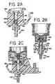
- FIG. 2A there is shown a detailed view of the ball chamber 432 and nozzle 430.
- the coupler 428 is formed where a hole in the coupler is offset for ball chamber 432 so that an inner edge of nozzle 430 protrudes into the outlet of ball chamber 432.
- Ball chamber 432 contains a ball 426 which fits loosely against the cylindrical surface of ball chamber 432 and is free to move between an uppermost position and a lowermost position. In its uppermost position, ball 426 mates with the ball check valve insert 424, thereby preventing fluid flow in the direction from nozzle 430 to dispense chamber 412. At its lowermost position, the ball 426 is restrained by inner edge of nozzle 430 and prevented from falling into nozzle 430. This does not prevent fluid from flowing from ball chamber 432 to nozzle 430, however.
- fluid dispenser 400 is in the positions shown in FIGS. 1A and 1B.
- a downward force is applied against cap 402. This overcomes the force of compression spring 418 and forces the barrel 408 downward until it reaches the top of the stop 420, thereby dispensing a predetermined volume of liquid equal to approximately 100 ⁇ L. This is equal to the liquid volume of the area that the barrel 408 moves down minus the "suck back" (which is the amount of fluid that travels past the ball on the upstroke of the barrel 408 before the ball 426 shuts off the flow).
- the fluid flows from dispense chamber 412 into ball chamber 432.
- the downward flow through ball chamber 432 forces ball 426 to its lowermost position, abutting edge 434, but this does not prevent flow in this direction and the measured amount of fluid is ejected from nozzle 430.
- FIGS. 2B and 2C there is shown a front and side cutaway of the lower portion of the fluid dispenser 400, respectively, in an alternative embodiment of the invention wherein the ball check valve insert 424 and ball 426 are removed.
- the piston 454 on the end of the barrel 408 has an extension piece 456 connected to it. In this manner, when the barrel 408 is raised upward, the extension piece 456 moves upward as well, thereby retracting any drops on the edge of the nozzle 430.
- FIG. 2B shows the barrel is in the down position.
- the O-ring 810 travels with the extension piece 454, which is attached to the piston 454, until the O-ring 810 seats against the chamfer 808.
- the extension piece 454 acts as a piston extension.
- the chamfer 808 is housed inside the O-ring insert 812 and is fixed during movement of the piston.
- the O-ring insert 812 is connected to the coupler 428.
- the fluid travels with the extension piece 454, and the drop at the end of the tip of the dispenser travels with the fluid due to surface tension. Therefore, the hanging drop is pulled back into the nozzle 430. Moreover, with the barrel 408 in the up position, fluid does not travel through the holes 806 due to the O-ring 810 seating inside the chamfer 808. In this embodiment, the ball and ball check valve insert is not necessary.
- FIGS. 3A and 3B there are shown exploded views of a cutaway of a prefilled and user fillable fluid dispenser 400, respectively. Differences between the prefilled and the user fillable fluid dispensers include: (1) the snap cap 404, as shown in FIGS. 3A and 3B; the barrel 408 being transparent in the user fillable fluid dispenser; and (3) the lack of an evaporation ring 405 in the user fillable fluid dispenser. Fluid can be filled into the reservoir through a fill hole and subsequently closed using a snap cap 404 in order to close the system. For prefilled fluid dispensers, the snap cap 404 is permanently attached over the fill hole after filling.
- the fill hole and the snap cap 404 are matched using a luer fitting design in order to be a tight seal, as shown in FIG. 5.
- the user fillable fluid dispenser 400 utilizes a living hinge design and luer slip design between the fill hole and the flip cap 402.
- the cap 406, as previously described, is sonically welded to the barrel 408.
- the cap 406 also has a vent 460, which is described subsequently with respect to FIG. 5.
- the duckbill check valve insert 414 holds the duckbill check valve 416 in place and creates a seal so that fluid cannot drip either from the dispense chamber 412 to the reservoir chamber 410 or from the reservoir chamber 410 to the dispense chamber 412.
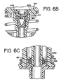
- the duckbill check valve insert 414 has a protrusion, or a nipple, which holds the duckbill to it for ease of assembly, as shown in more detail in FIG. 6B.
- the duckbill check valve 416 which serves as a check valve, is snapped to the duckbill check valve insert 414.
- the duckbill check valve 416 is a one way valve with a high cracking pressure of between .6 to 3.0 psi. This acts to hold the fluid in the reservoir chamber 410 since the cracking pressure is greater than the head pressure of fluid in the reservoir chamber 410.
- the duckbill passes fluid from the reservoir chamber 410 to the dispense chamber 412 on the upstroke of the barrel 408 while preventing fluid to pass during the downstroke of the barrel 408.
- the duckbill check valve 416 and duckbill check valve insert 414 are seated in the lower portion of the barrel 408 as shown in FIG. 6A.
- the spring 418 is a compression spring which expands and contracts based on the movement of the barrel 408.
- the stop 420 stops the downward stroke of the barrel 408.
- the stop also holds the quad seal 422 in place during movement of the fluid dispenser 400 and composed of polypropylene.
- the stop 420 is held in place based on the compression spring 418 with the force varies based on the movement of the barrel 408.
- the stop 420 is held in place, in turn, keeps the quad seal 422 in place via a ledge 420A, as shown in FIG. 6C, on the stop 420.
- the quad seal 422 ensures that the fluid dispenser 400 is always a closed system thereby keeping the fluid dispenser 400 primed.
- the quad seal 422 is made of VitonTM rubber that is a fluoroelastomer, and is distributed by Lutz Sales, in Hanover Park, Illinois, part number QS-008-2799.
- the ball check valve insert 424 is a separate part from the coupler 428 and is seated inside the coupler 428, being snapped into place by grooves in the chamber of the coupler 428 and by being seated on a ledge 428A, as shown in FIG. 6A.
- the ball check valve insert 424 has a ball seat 424A on the inside with which to engage the ball 426 on the upstroke of the barrel 408. Previous fluid dispensers integrated the coupler with the ball check valve insert for the ball.
- the ball 426 is made of borosilicate (which is a type of glass).
- a ball 426 composed of rubber may be used. In certain instances, a rubber ball may seat better in the plastic ball check valve insert 424, provided there is no chemical interaction of the rubber ball with the reagents.
- the duckbill check valve 416 and duckbill check valve insert 414 are placed in the lower part of the barrel 408.
- the cap 406 is welded to the barrel.
- the ball 426 is placed, the ball check valve insert 424 is snapped and then the quad seal 422 is inserted into the coupler 428.
- the stop 420 and the spring 418 are inserted into the coupler 428 and the coupler 428 is snapped on to the barrel 408.
- the barrel 408 is filled with reagent and the fluid dispenser 400 is primed.
- the cap 404 is placed on the top of the dispenser and the nozzle cap 458 is placed on the output of the nozzle 430 on the coupler 428.
- the cap is sonically welded or screwed onto the top of the barrel 408.
- the cap 406 is first sonically welded to the barrel 408, and then the reagents are added to the reservoir chamber 410. In this manner, there are fewer steps in the filling of the dispenser.
- some of the more manufacturing sensitive parts are smaller, thereby making manufacturing easier.
- the material used is polypropylene. Under these conditions, smaller parts have a higher level of dimensional stability. Therefore, smaller components, such as the ball check valve insert 424 (which is, in the present invention, a separate component from the coupler 428) are able to be processed more consistently.
- the syringe may be manufactured by B-D Corp., in Franklin Lakes, New Jersey, size 20cc, part number BC301032.
- the syringe 459 has a restrictor 459A and an O-ring 459B.
- the restrictor 459A has an internal diameter of approximately 5 thousandths of an inch.
- the syringe 459 is placed inside the nozzle 430 of the coupler 428 and the syringe plunger is expanded to draw fluid from the reservoir chamber 410 and the dispense chamber 412.
- the barrel 408 is pushed down, and is released simultaneously when the syringe plunger is expanded. In this manner, there is significantly less waste of reagent.
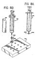
- FIG. 8B there is shown an exploded view of the syringe 459 (and a syringe label 788) with a restrictor 459A and an O-ring 459B for use in the nozzle of the coupler.
- the O-ring 459B is placed on the side of the restrictor 459A that does not have the v-notch in it.
- the restrictor 459A, with the O-ring 459B side down, is placed into a holding fixture 790, as shown in FIG. 8B.
- the syringe 459 is then pressed onto the restrictor 459A for assembly.
- the restrictor 459A is made by Airlogic, in Racine, Wisconsin, part number F-2815-050 (color: lime green), with a one inch orifice for the restrictor 459A.
- the O-ring 459B is manufactured by Parker Co., in Lexington, Kentucky, part number 2-003.
- the restrictor 459A fits well in the nozzle of the syringe 459 so that the syringe 459 does not need the O-ring 459B to seat against the coupler. Because of potential differences in mold runs for the coupler 428 of the fluid dispenser 400, the O-ring 459B is used so that the restrictor 459A fits tightly against the coupler 428.
- the customer may flip the dispenser upside-down, tap the dispenser, dislodging any trapped air then pressing down on the barrel slowly to move the air bubble past the ball seat.
- the customer may then flip the coupler right-side-up and release the barrel. Good priming occurs with approximately one drop of waste.
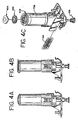
- FIG. 4C there is shown an exploded view of a prefilled fluid dispenser with an evaporation ring 405 adjacent to the cap.
- the interaction of the vent, the evaporation ring 405 and the cap are discussed subsequently with respect to FIGS. 5A-E.
- the barcode label 784 is placed on the dispenser in order to be read by the barcode reader 276.
- the dispenser label 786 is also placed on the dispenser.
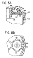
- FIG. 5A there is shown a cutaway view of the cap 406 and vent 460 of a fluid dispenser 400.
- the vent is the component adjacent the top of the cap and includes the vent area 464, vent material 466, and backing 468.
- the vent 460 is used as a means to allow air to flow both into and out of the reservoir chamber 410 (i.e., so that the reservoir chamber can "breathe”).
- the vent 460 allows for a constant pressure in the reservoir chamber and equalizes the pressure in the reservoir chamber 410 with the pressure in the atmosphere.
- There are several ways in which to construct the vent in order to maintain a constant pressure in the reservoir chamber 410 and/or equalize the pressure in the reservoir chamber 410.
- the vent area is approximately 70 thousandths of an inch, with a vent material 466 composed of a hydrophobic material.
- a vent material 466 composed of a hydrophobic material.
- the vent area is reduced to approximately 10 thousandths of an inch, thereby reducing the amount of evaporation from the reservoir chamber 410.
- processing a fluid dispenser with a reduced vent area is more difficult due to the corresponding reduced area of the vent material.
- the vent area 464 may be any area.
- the vent material may be composed of a tighter material, thereby reducing the air flow through the vent material and reducing the amount of evaporation through the vent area 464.
- the vent material is 1 ⁇ m in the size of the mesh. Reducing the size of the mesh, such as to .25 ⁇ m, further reduces the amount of evaporation through the vent area 464.
- the vent area may be any area and a section of tape is placed across the vent area. The tape contains a pin hole whereby the vent area is effectively reduced thereby reducing the amount of evaporation.
- the cap 406 and snap cap 404 are luer fitting design so that the cap 406 and snap cap 404 portion which engage each other to seal the fill hole is conical.
- a ring or a lip 462 At the lower portion of the conical section of the snap cap 404 is a ring or a lip 462 that is used to snap the snap cap 404 into place.
- the snap cap 404 is pushed down until it locks into the cap 406.
- the snap cap 404 has a curved section 472 that abuts against a curved section of the cap thereby stopping the snap cap 404 at that point.
- the snap cap 404 also engages the cap 406 to form an air space 474 that is adjacent to the vent area.
- This air space 474 forms a ring, so that regardless of the orientation of the snap cap to the cap, a hollow section is adjacent to the vent area 464 (which is approximately 70 thousandths of an inch or less). Further, the outside diameter of the snap cap 404 is slightly smaller than the inner diameter of the cap 406 so that a small air gap 476 is formed adjacent to the air space 474 to the outside of the dispenser.
- the air space 474 serves as a path from the vent 460 to the outside atmosphere as well as serving as a buffer between the outside of the dispenser and the vent 460.
- the air gap 476 may be used in conjunction with a notch in the side of the cap, as shown in FIG. 4C. This notch allows more air into the air gap 476, in the event that the greater air flow is required. Moreover, the notch may replace the air gap 476, so that the sole means of air flow into the air space 474 is through the notch.
- the vent 460 is a hydrophobic vent which allows air to flow through the vent while keeping fluid trapped inside the reservoir chamber 410.
- the vent is composed of a filter material 466 such as a teflon material with a backing to attach the vent to the cap.
- the vent opening or area 464 as described previously, is approximately 70 thousandths of an inch.
- the pressure inside the reservoir chamber 410 is constant, even though the level of reagent may be changing inside the reservoir chamber 410 since air is allowed to flow into the reservoir chamber 410. Moreover, some reagents produce a by-product of gas (called outgassing).
- the hydrophobic vent 460 allows gas through the vent 460, thereby avoiding any pressure build-up inside the reservoir chamber 410.
- previous fluid dispensers that required a piston to exert force on the fluid in the reservoir chamber 410 may be removed.
- the piston in previous designs suffered from several drawbacks.
- certain reagents such as proteins
- the interaction between the piston and the barrel rely on lubricants.
- Certain reagents are composed, in part, of detergents and the detergents interfere with the lubrication between the piston and the barrel. Both effects interfere with the performance of the fluid dispenser, thereby giving inconsistent dispensing of fluid.
- outgassing interacts with the piston either to increase the flow out of the reservoir chamber 410 or to create a compressible air gap between the piston and the main section of the reservoir chamber 410.
- quad seal 422 is coated with fluorine. Fluorine reacts with the outer layer of the quad seal 422, thereby discouraging reactions with certain types of reagents.
- the evaporation ring 405 is composed of low density polyethylene material manufactured by Whitmark (vendor part number 105060), and is 1/8 inch thick. As discussed previously, the ring acts as a barrier, making it more difficult for air to pass across the vent. In this manner, the ring acts as a restrictor (of air), thereby reducing the amount of evaporation, while still allowing the reservoir chamber 410 to breathe.
- the ring is a closed cell foam, and is inexpensive in nature.
- the ring may be composed of any material or foam that acts to restrict the air across the vent area 464.
- FIG. 5A there are protrusions 470 on the inside upper portion of the cap 406 which are used to align the piece of vent material.
- the vent 460 is therefore centered on top of that upper portion of the cap 406.
- FIG. 5B there is shown an underside view of the vent 460. Included with the vent 460 is a platform 468 for the vent 460, star-shaped in design, which holds the vent 460 flat. When air is passing through the vent 460, particularly when outgassing, the vent 460 has a tendency to flex which may damage the teflon in the vent. In order to minimize flexing of the vent 460, the platform 468 is adjacent to the vent.
- the surface area of the vent may still be relatively large but still have a grid support to stabilize the vent 460 during outgassing.
- the platform 466 is star-shaped due to ease of molding; however, the shape of the platform may be any design, which supports or stabilizes the vent.
- the vent may be substituted with a bi-directional valve 478 or bi-directional duckbill (or two valves or two duckbills) as another means by which to allow air to flow into and out of the reservoir chamber 410.
- the bi-directional valve 478 has a bi-directional valve insert 480 for placement of the bi-directional valve 478.
- the bi-directional valve 478 also has a hydrophobic layer which allows air to flow through the bi-directional valve 478 while keeping fluid trapped inside the reservoir chamber 410. In one direction (air flowing into the reservoir chamber 410), the bi-directional duckbill 478 has a low cracking pressure, in order to equalize the pressure in the reservoir chamber 410 when fluid is dispensed.
- the bi-directional duckbill 478 In the second direction (air flowing out of the reservoir chamber 410), the bi-directional duckbill 478 has a high cracking pressure, in order to alleviate any pressure due to outgassing.
- the bi-directional duckbill 478 allows air to flow through while keeping fluid trapped inside the reservoir chamber 410. Therefore, the bi-directional duckbill 478 allows air to flow into and out of the reservoir chamber 410 and allows for equalization of the pressure.
- a bi-directional duckbill 478 may have less refinement in terms of control when compared to two uni-directional duckbills.
- the bi-directional duckbill 478 may be replaced by two uni-directional duckbills, as shown in FIG. 5D.
- the system becomes a three duckbill system.
- the duckbill that releases to atmosphere has the light cracking pressure
- the duckbill that allows air into the reservoir chamber has the light cracking pressure
- the duckbill check valve 416 that is down in the barrel has a medium cracking pressure.
- the duckbill check valve 416 in the barrel should be of a higher cracking pressure than the duckbill releasing air to the atmosphere so that pressure built up in the reservoir should be relieved through the lighter cracking pressure duckbill.
- vent 460 may be substituted with a uni-directional valve or duckbill 482, (made by Vernay in Yellow Springs, Ohio, part number VL-857-101) with a duckbill valve insert 484.
- the uni-directional duckbill 482 has a low cracking pressure to alleviate pressure due to outflow of fluid from the reservoir chamber 410.
- vent material is not required since the air is flowing only into the reservoir chamber.
- the vent opening 464 may be reduced to approximately 10 thousandths of an inch (from 70 thousandths of an inch as shown in FIG. 5A).
- the snap cap 404, for prefilled fluid dispensers, or the flip cap 402, for user fillable fluid dispensers, may also be modified to include a seal 488 where the snap cap 404 or flip cap 402 engages the cap 406.
- this alternative embodiment does not have a gap 476 between the snap cap 404 (or flip cap 402) and the cap 406, but instead includes a seal 488.
- the mechanical valve operates such that in one position, a hole in the fluid dispenser is sealed, and in another position, the valve does not seal the hole.
- the biasing member of the valve without external mechanical force biases the stem such that at least a portion of the stem seals the hole in the fluid dispenser.
- the stem which is connected to or integral with the biasing member, moves, thereby unsealing the hole in the fluid dispenser. Subsequently, the biasing member, without external force, biases the stem again such that the stem does not seal the hole.
- Applying mechanical force to at least a portion of the biasing member moves the stem so that at least a portion of the stem seals the hole in the fluid dispenser.
- the biasing member without external mechanical force seals the hole in the fluid dispenser so that by applying a mechanical force, at least a portion of the hole is unsealed.
- an elastomeric mechanical valve and in one embodiment, an umbrella valve
- the reservoir of the fluid dispenser may be sealed.
- the umbrella valve is not used in the normal manner as known to those skilled in the art.
- Umbrella valves are normally used as pressure actuated check valves that seal against flow in one direction and are opened by pressure in the other direction.
- the outer flange of the umbrella is urged against a flat sealing surface by the spring force of the deflected umbrella. Fluid pressure on top of the umbrella valve only tends to further seal the flange to its mating seat.
- the valve is opened by pressure under the umbrella pushing it away from its mating surface, allowing fluid to pass between the flange and its mating sealing surface.
- One aspect of the invention makes a mechanical valve out of an umbrella valve, instead of a pressure actuated valve, by using the bulge on the stem, urged against a sharp corner at the end of a hole through which the stem passes as a sealing point.
- the flange is prevented from sealing by adding slots to its mating surface.
- the flanged head is used as a disk spring to urge the bulge to seal against it seat, which is opened when the center of the umbrella is deflected downward by the dispenser actuator.
- the movement of the center of the umbrella downward, or at least a portion of the umbrella downward pushes the stem and its associated bulge down, uncovering the sealing area, thereby opening the valve and venting the reservoir.
- An oliophobic vent may be added in series to provide additional safety in preventing liquid from leaking out even if the mechanical vent fails.
- this provides a method and apparatus to modify the pressure in a fluid dispenser.
- This further provides a method and apparatus that prevents a vacuum from forming in the reservoir chamber of a fluid dispenser while the liquid contained in the dispenser may be pumped out, and at the same time preventing a pressure buildup in the reservoir due to outgassing during the pumping cycle.
- the method and apparatus can prevent liquid from leaving the reservoir through an insert vent that may be placed underneath the mechanical valve of the fluid dispenser.
- the method and apparatus can prevent the vapor of an evaporated reagent from leaving the reservoir chamber. Finally, this may eliminate the need for a circuitous path or the use of foam between the vent and the surroundings as has been used in the past.
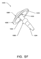
- FIG. 5F an assembly of a valve 1000 is shown arranged to operate in accordance with one embodiment of the present invention.
- the valve may take a variety of forms such as an umbrella shape, as shown in Figure 5F, or any other shape consistent with the operations of the mechanical valve. Examples of other forms consistent with the operations of the mechanical valve include, but are not limited to: a spring mechanism, or an elastomeric mechanism.
- the valve 1000 may have a stem with two portions, either being an integral piece or a series of pieces.
- the upper portion 1002 of the stem may connect to the head 1008 of the valve 1000.
- the head 1008 may be a flanged head as shown in Figure 5F.
- Other forms may include a flat surface, or a non-circular head.
- the fluid in a fluid dispenser may be dispensed by movement of the barrel.
- An example of a barrel is shown in Figure 1A.
- the fluid dispenser may be placed into a machine with a plunger 6000, or other means of applying force, to press down upon the barrel of the fluid dispenser.
- the plunger 6000 may contact the cap 2000 of the fluid dispenser.
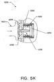
- the plunger 6000 of the machine may mechanically open the valve 1000 as shown in Figure 5K.
- the plunger 6000 on the machine contacts the fluid dispenser the plunger 6000 may first contact the top of the head 1008 of the valve 1000 which is inserted into the cap 2000. Any portion of the head 1008 may be contacted.
- the head 1008 of the valve 1000 may be deflected downward because the head 1008 is made of an elastomeric material.
- the head 1008 may be deflected downward until the plunger 6000 contacts protective ridge 2006.
- the contact of the annular portion 1009 of the head 1008 with the surface 2002 does not prevent air from passing underneath the valve 1000.
- the head 1008 of the valve 1000 may be positioned on top of the surface 2002 of the cap 2000, air may be able to pass underneath the valve 1000 through the cuts.
- the cuts on the surface 2002 allow for passageways for air to pass underneath the valve 1000.
- the valve 1000 contacts the surface 2002 upon mechanically opening the valve 1000, but the cut are made in the surface 2002, and thus allow for air to pass underneath the valve 1000.
- the head 1008 Upon deflection of the head 1008, the head 1008 exerts a force onto the stem portion of the valve 1000.
- the upper portion 1002 of the valve 1000 may transmit the force from the head 1008 onto the bulge 1006 which displaces the bulge 1006 from the hole 2004.
- the valve 1000 will be open as shown in Figure 5K. Since the hole 2004 is of a smaller diameter than the stem of the valve 1000, a space may be present between the upper portion 1002 of the stem and the outer area of the hole 2004. This may allow for the pressure in the reservoir to equilibrate with that of the surrounding atmosphere by allowing air to pass through the space 6004 between the upper portion 1002 of the stem and the outer area of the hole 2004, and subsequently pass through the cut.
- the cut on the surface 2002 of the cap 2000 allow for a passageway of free communication of air between the outer atmosphere and the inside of the reservoir chamber when the bulge 1006 is displaced from the hole 2004.
- Air may pass through the cut underneath the valve 1000 because of a pressure differential between the inside of the reservoir chamber and the outside of the reservoir chamber. The air will move from a region of higher concentration of pressure to a region of a lower concentration of pressure.
- the pressure inside the fluid dispenser may be higher than the pressure on the outside of the fluid dispenser.
- the pressure inside the fluid dispenser may be lower than the pressure on the outside of the fluid dispenser. Air may pass out of the fluid dispenser until the pressure inside the fluid dispenser is equal to the pressure outside the fluid dispenser.
- the seal of the bulge 1006 against the hole 2004 may be re-formed to disallow air to pass underneath the valve 1000 upon removing the plunger 6000 from the top of the head 1008 of the valve 1000.
- the head 1008 may not be deflected, and the head 1008 may slowly re-form due to the stored potential spring energy of the head 1008 of the valve 1000 and pull the upper potion 1002 and the lower portion 1004 of the stem of the valve 1000 upward a small distance.
- the bulge 1006 may move upward as well.
- the bulge 1006 may then become pressed against the hole 2004 of the cap 2000 and form a tight seal.
- a portion of the stem may become compressed upon moving the stem upward.
- the bulge 1006 may become compressed as well upon pressing the bulge 1006 against the hole 2004 to form a tight seal.
- Using the elastomeric valve 1000 may seal the reservoir of the fluid dispenser.
- a requirement of a valve is for the valve to have a dual-purpose vent.
- the first purpose is to allow air to pass into the reservoir to prevent a vacuum from forming as liquid is removed.
- the second purpose of the vent is to allow any internal pressure that might build up inside the reservoir to equilibrate with ambient pressure before the first dispense. Internal pressure is not in itself a substantial problem. However, internal pressure may not be tolerated when the dispenser is actuated, as the pressure would expel too large of a volume of liquid.
- the valve 1000 provides a manner of sufFciently venting the fluid dispenser.
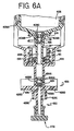
- FIG. 6A there is shown a cutaway view of the lower portion of the barrel 408, duckbill check valve 416, duckbill check valve insert 414, quad seal 422, ball 426, ball check valve insert 424 and coupler 428 of a fluid dispenser 400.
- the barrel 408 has protrusions 408A, which mate with the coupler in order to, maintain the position of the barrel 408 on the upstroke. Otherwise, if the spring pushes the barrel 408 upward too high, the seal, as provided by the quad seal 422, may be broken thereby creating an air path and causing the fluid dispenser 400 to lose prime.
- the barrel 408 also has a flange 408B which mates with the stop 420 on the downstroke.
- the barrel 408 also has a pocket 408C, where the duckbill check valve insert 414 is inserted. This pocket acts as a funnel so that no puddles are formed at the bottom of the barrel 408 at the interaction point with the duckbill check valve 416 or duckbill check valve insert 414, thereby minimizing waste.
- the barrel 408 also has at its lower portion a piston 454 by which fluid is expelled in the dispenser 400.
- a nozzle cap 458 for engagement with the nozzle 430 of the coupler 428.
- the nozzle cap 454 and nozzle 430 are matched using a luer fitting design in order to be a fluid tight seal. Referring to FIG.
- FIG. 6B there is shown a cutaway view of the lower portion of the barrel, duckbill check valve, and duckbill check valve insert of a fluid dispenser.
- FIG. 6C there is shown a cutaway view of the quad seal of a fluid dispenser.
- FIG. 6A also shows a cutaway view of the coupler 428.
- the coupler 428 has grooves 428B in which the ball check valve insert 424 snaps.
- the grooves 428B act to prevent any leakage of fluid downward or air upward through the walls of the ball check valve insert 424 and the coupler wall.
- the coupler 428 also has protrusions 428C, which ensure that the dispenser is aligned on the reagent tray 10. For example, if the dispenser is misaligned, the dispense cylinder may not engage the dispenser properly.
- the coupler also has stabilizing bumps 428D, which reduce any rocking back and forth of the fluid dispenser 400.
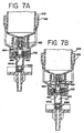
- FIG. 7A there is shown a barrel 408 which has a lower section which acts as a piston 454 at its lower end, similar to FIGS. 1A-1C.
- a throughhole at the bottom of the piston 454 at the lower section of the barrel in the piston area
- the pressure differential is such that the duckbill check valve 482 opens and fills the dispense chamber 410 with fluid.
- the duckbill check valve 482 in FIG. 7A is a duckbill check valve of low cracking pressure. Further, when the barrel is in the up position, the end of the piston 454A is closed by the O-ring seals 452 thereby sealing the bottom of the barrel 408 except for the holes 450.
- FIG. 7B there is shown a barrel 408 which has a lower section which acts as a piston 454 at its lower end, similar to FIG. 7A.
- a quad seal 422 is used instead of placing O-ring seals 452 to cover the hole 450 in the lower end of the piston 454A.
- FIG. 9 there is shown an alternative embodiment of a cutaway view of the lower portion of the fluid dispenser with a cup check valve 792.
- the lower portion of the cup check valve 792 i.e., the cup piece 794 abuts against the piston 454 of the barrel 408, thereby disallowing liquid to pass through the lower portion of the barrel 408.
- the upper portion of the cup check valve 792 which is composed of an upper ledge 800 and side walls 802, abuts against the duckbill check valve insert 414 and the side of the piston 454.
- the cup check valve 792 operates in a manner similar to the duckbill check valve 416, as shown in FIG. 6A in that it operates based on a pressure differential.
- the cup piece 794 of the cup check valve 792 remains rigid so that the piston, and the cup piece, push the liquid out of the dispense chamber 412.
- the ball 434 in the ball chamber 432 seats against the check valve ball insert 424, as described in FIG. 2A, creating a vacuum in the dispense chamber.
- This vacuum creates a pressure in the dispense chamber and in the adjacent piston area of the barrel 408, causing the cup piece 794 of the cup check valve 792 to flex inward, so that the cup piece 794 does not abut against the piston 454.
- fluid in the reservoir chamber is allowed to pass around the cup check valve 792 and into the dispense chamber.
- the cup piece 794 is flexed inward until the pressure equalizes between the dispense chamber and reservoir chamber. As such, the dispense chamber receives fluid on the upstroke of the barrel 408. For better flexing effect due to the vacuum caused in the dispense chamber, the cup piece 794 of the cup check valve 792 should sit low in the piston 454 of the barrel 408. In this manner, the less area under the cup, the more suction effect caused by the vacuum.
- FIG. 10A there is shown a side view of the cup check valve 792.
- the cup piece 794 spreads outward at angle of approximately 71° from the horizontal.
- the cup piece 794 may be curved outward or inward, depending on the flexing needs of the cup piece 794.
- the upper ledge 800 and side walls 802 are formed to abut against the duckbill check valve insert 414 and the side of the piston 454. This upper piece may be of such a form in order to be held securely in place.
- FIG. 10B there is shown a bottom view of the cup check valve 792.
- the bottom 796 is round, in order to abut the round sidewalls of the piston 454.
- the bottom of the cup check valve 792 may be any shape that forms against the surface abutting it, in this case, the piston 454.
Landscapes
- Life Sciences & Earth Sciences (AREA)
- Health & Medical Sciences (AREA)
- General Health & Medical Sciences (AREA)
- Chemical & Material Sciences (AREA)
- Analytical Chemistry (AREA)
- Biochemistry (AREA)
- Physics & Mathematics (AREA)
- General Physics & Mathematics (AREA)
- Immunology (AREA)
- Pathology (AREA)
- Engineering & Computer Science (AREA)
- Biomedical Technology (AREA)
- Molecular Biology (AREA)
- Automatic Analysis And Handling Materials Therefor (AREA)
- Containers And Packaging Bodies Having A Special Means To Remove Contents (AREA)
Claims (22)
- Distributeur de fluide comprenant de manière combinée :- un corps (408) possédant un bouchon, le bouchon (2000) ayant une surface avec au moins un trou (2004) ; et- une valve (1000) possédant un élément de sollicitation (1008) et un obturateur de trou (1006), l'élément de sollicitation (1008) ayant au moins deux positions,dans lequel dans une première position de l'élément de sollicitation (1008), l'obturateur de trou (1006) bouche le trou (2004) et dans lequel dans une deuxième position, l'obturateur de trou ne bouche pas le trou (2004),
dans lequel une force place l'élément de sollicitation (1008) dans au moins l'une des deux positions
et dans lequel l'élément de sollicitation (1008) est un élément de sollicitation en forme de parapluie avec une surface plane (1010), le pourtour de la surface plane (1010) entrant en contact avec le bouchon (2000),
caractérisée en ce que
ledit bouchon (2000) comprend en outre un passage du trou vers l'extérieur, le distributeur de fluide comprenant une ou plusieurs cassures (2008), lesdites cassures (2008) s'appuyant sur au moins une partie de la surface plane (1010) de l'élément de sollicitation en forme de parapluie (1008). - Distributeur de fluide selon la revendication 1, dans lequel l'obturateur de trou (1006) est un renflement de forme sensiblement sphérique.
- Distributeur de fluide selon l'une des revendications précédentes, dans lequel les cassures (1008) fournissent un trajet de fluide.
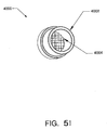
- Distributeur de fluide selon l'une des revendications précédentes, comprenant en en outre un évent (4000) à l'intérieur du corps (408).
- Distributeur de fluide selon la revendication 4, dans lequel l'évent (4000) comprend un matériau oléophobe (4004).
- Distributeur de fluide selon la revendication 4 ou 5, dans lequel le corps (408) comprend une chambre de réservoir (410) et dans lequel l'évent (4000) permet à de l'air d'entrer dans la chambre de réservoir (410).
- Distributeur de fluide selon l'une des revendications précédentes, dans lequel au moins une partie de la valve (1000) est constituée d'un matériau élastomère.
- Distributeur de fluide selon l'une des revendications précédentes, dans lequel la force est mécanique.
- Procédé d'équilibrage de pression à l'intérieur du distributeur de fluide comprenant les étapes consistant à :fournir le distributeur de fluide selon l'une
des revendications 1 à 8.placer l'élément de sollicitation (1008) dans l'une
des deux positions en exerçant une force sur la valve (1000),dans lequel dans une première position de l'élément de sollicitation (1008), l'obturateur de trou (1006) bouche le trou (2004) et dans lequel dans une deuxième position, l'obturateur de trou (1006) ne bouche pas le trou (2004). - Procédé selon la revendication 9, dans lequel la force place l'élément de sollicitation (1008) dans la deuxième position.
- Procédé selon la revendication 9 ou 10, dans lequel la force place l'élément de sollicitation (1008) dans la première position.
- Procédé selon l'une quelconque des revendications 9 à 11, dans lequel l'élément de sollicitation (1008) est une surface façonnée avec un sommet, dans laquelle la force mécanique est exercée au sommet.
- Procédé selon l'une quelconque des revendications 9 à 12, comprenant en outre la fourniture d'un passage pour de l'air entre l'intérieur et l'extérieur du corps lorsque le corps (408) est dans la deuxième position.
- Distributeur de fluide selon l'une quelconque des revendications 9 à 13, dans lequel le corps comporte une chambre de réservoir (410) et dans lequel le distributeur de fluide comprend en outre un évent (4000) à l'intérieur du corps, et dans lequel l'évent (4000) permet à de l'air d'entrer dans la chambre de réservoir (410).
- Procédé selon l'une quelconque des revendications 9 à 14, dans lequel le fait de placer l'élément de sollicitation (1008) dans l'une des deux positions comporte l'application d'une force mécanique.
- Procédé consistant à faire fonctionner mécaniquement la valve pour un distributeur de fluide selon l'une quelconque des revendications 1 à 8, la valve (1000) comportant en outre une tête (1008) et un renflement (1006), le procédé comprenant les étapes consistant à :mettre en appui le renflement (1006) contre le trou (2004) dans le bouchon du distributeur de fluide (2000) pour créer un joint d'étanchéité ;exercer une force mécanique pour déplacer la tête (1008) de façon à ce que le renflement (1006) ne vienne pas en appui sur le trou (2004) ; etréduire la force mécanique de façon à ce que le renflement (1006) vienne en appui sur le trou (2004).
- Procédé selon la revendication 16, dans lequel la tête (1008) comporte un élément de sollicitation et dans lequel l'étape de la mise en appui est exécutée par l'élément de sollicitation.
- Procédé selon la revendication 16 ou 17, dans lequel l'étape consistant à réduire la force mécanique comporte la suppression de la force mécanique créant ainsi le joint d'étanchéité entre le renflement (1006) et le trou (2004).
- Procédé selon l'une quelconque des revendications 15 à 18, dans lequel la tête (1008) possède une partie centrale et dans lequel la force mécanique est exercée sur la partie centrale de la tête (1008).
- Procédé selon l'une quelconque des revendications 16 à 19, dans lequel l'étape consistant à exercer une force mécanique sur la tête (1008) crée une ouverture entre le renflement (1006) et le trou (2004) pour permettre un passage entre l'intérieur du distributeur de fluide (408) et l'extérieur du distributeur de fluide (408).
- Procédé selon l'une quelconque des revendications 16 à 20, dans lequel le corps comporte une chambre de réservoir (410) et dans lequel le distributeur de fluide comprend en outre un évent (4000) à l'intérieur du corps, et dans lequel l'évent permet à de l'air d'entrer dans la chambre de réservoir (410).
- Procédé selon la revendication 21, dans lequel l'évent (4000) empêche le liquide de sortir de la chambre du réservoir (410).
Applications Claiming Priority (2)
| Application Number | Priority Date | Filing Date | Title |
|---|---|---|---|
| US10/060,602 US20020110494A1 (en) | 2000-01-14 | 2002-01-30 | Method and apparatus for modifying pressure within a fluid dispenser |
| US60602 | 2002-01-30 |
Publications (3)
| Publication Number | Publication Date |
|---|---|
| EP1333287A2 EP1333287A2 (fr) | 2003-08-06 |
| EP1333287A3 EP1333287A3 (fr) | 2004-05-12 |
| EP1333287B1 true EP1333287B1 (fr) | 2006-06-21 |
Family
ID=22030552
Family Applications (1)
| Application Number | Title | Priority Date | Filing Date |
|---|---|---|---|
| EP03000532A Expired - Lifetime EP1333287B1 (fr) | 2002-01-30 | 2003-01-09 | Méthode et appareil pour modifier la pression dans un dispenseur de fluide |
Country Status (5)
| Country | Link |
|---|---|
| US (1) | US20020110494A1 (fr) |
| EP (1) | EP1333287B1 (fr) |
| DE (1) | DE60306217T2 (fr) |
| DK (1) | DK1333287T3 (fr) |
| ES (1) | ES2266646T3 (fr) |
Cited By (1)
| Publication number | Priority date | Publication date | Assignee | Title |
|---|---|---|---|---|
| US7767152B2 (en) | 2003-08-11 | 2010-08-03 | Sakura Finetek U.S.A., Inc. | Reagent container and slide reaction retaining tray, and method of operation |
Families Citing this family (22)
| Publication number | Priority date | Publication date | Assignee | Title |
|---|---|---|---|---|
| US6093574A (en) | 1997-08-11 | 2000-07-25 | Ventana Medical Systems | Method and apparatus for rinsing a microscope slide |
| US8137619B2 (en) * | 1997-08-11 | 2012-03-20 | Ventana Medical Systems, Inc. | Memory management method and apparatus for automated biological reaction system |
| US7297311B2 (en) * | 2001-06-29 | 2007-11-20 | Sysmex Corporation | Automatic smear preparing apparatus and automatic sample analysis system having the same |
| US7368080B2 (en) * | 2002-01-18 | 2008-05-06 | Sysmex Corporation | Smear preparing apparatus |
| US8449822B2 (en) * | 2002-01-18 | 2013-05-28 | Sysmex Corporation | Smear preparing apparatuses and methods of preparing sample smears |
| US7378058B2 (en) * | 2002-01-30 | 2008-05-27 | Ventana Medical Systems, Inc. | Method and apparatus for modifying pressure within a fluid dispenser |
| US11249095B2 (en) | 2002-04-15 | 2022-02-15 | Ventana Medical Systems, Inc. | Automated high volume slide processing system |
| US7468161B2 (en) | 2002-04-15 | 2008-12-23 | Ventana Medical Systems, Inc. | Automated high volume slide processing system |
| US7648678B2 (en) | 2002-12-20 | 2010-01-19 | Dako Denmark A/S | Method and system for pretreatment of tissue slides |
| US6952950B2 (en) * | 2003-03-07 | 2005-10-11 | Waters Investment Limited | System and method for automatic identification of a detachable component of an instrument |
| US9518899B2 (en) * | 2003-08-11 | 2016-12-13 | Sakura Finetek U.S.A., Inc. | Automated reagent dispensing system and method of operation |
| US7875463B2 (en) * | 2004-03-26 | 2011-01-25 | Agilent Technologies, Inc. | Generalized pulse jet ejection head control model |
| GB0420878D0 (en) * | 2004-09-20 | 2004-10-20 | Randox Lab Ltd | Reagent holder and testing assembly incorporating a reagent holder |
| US8459509B2 (en) | 2006-05-25 | 2013-06-11 | Sakura Finetek U.S.A., Inc. | Fluid dispensing apparatus |
| US7875242B2 (en) * | 2006-10-17 | 2011-01-25 | Preyas Sarabhai Shah | Slide stainer with multiple heater stations |
| AU2009313985B2 (en) | 2008-11-12 | 2014-07-31 | Ventana Medical Systems, Inc. | Methods and apparatuses for heating slides carrying specimens |
| US8276616B2 (en) | 2009-03-20 | 2012-10-02 | Xylem Ip Holdings Llc | High pressure duckbill valve and insert |
| US8752732B2 (en) | 2011-02-01 | 2014-06-17 | Sakura Finetek U.S.A., Inc. | Fluid dispensing system |
| WO2012163992A1 (fr) | 2011-06-01 | 2012-12-06 | Ventana Medical Systems, Inc. | Distributeur avec dispositif à filtre |
| US8580568B2 (en) | 2011-09-21 | 2013-11-12 | Sakura Finetek U.S.A., Inc. | Traceability for automated staining system |
| US8932543B2 (en) | 2011-09-21 | 2015-01-13 | Sakura Finetek U.S.A., Inc. | Automated staining system and reaction chamber |
| EP3080579B1 (fr) | 2013-12-13 | 2022-07-27 | Ventana Medical Systems, Inc. | Appareil de traitement automatisé des lames |
Family Cites Families (35)
| Publication number | Priority date | Publication date | Assignee | Title |
|---|---|---|---|---|
| US2234079A (en) * | 1938-12-09 | 1941-03-04 | Faultless Rubber Co | Fluid dispenser |
| US3650347A (en) * | 1969-10-03 | 1972-03-21 | Adolph J Campos | Automobile safety and anti-theft device |
| US3695281A (en) * | 1970-11-16 | 1972-10-03 | Technicon Instr | Method and apparatus for fluid injection |
| BE788877A (fr) * | 1971-09-17 | 1973-01-02 | Vickers Ltd | Agitation d'echantillons liquides pour l'obtention de melanges homogenes |
| DE3133191C2 (de) * | 1980-08-22 | 1986-01-16 | Olympus Optical Co., Ltd., Tokio/Tokyo | Automatisches chemisches Analysiergerät |
| JPH0217341Y2 (fr) * | 1981-02-10 | 1990-05-15 | ||
| US4964544A (en) * | 1988-08-16 | 1990-10-23 | Bobrick Washroom Equipment, Inc. | Push up dispenser with capsule valve |
| US5595707A (en) * | 1990-03-02 | 1997-01-21 | Ventana Medical Systems, Inc. | Automated biological reaction apparatus |
| US5425918A (en) * | 1990-07-18 | 1995-06-20 | Australian Biomedical Corporation | Apparatus for automatic tissue staining for immunohistochemistry |
| CA2025105A1 (fr) * | 1990-09-11 | 1992-03-12 | Garth T. Webb | Dispositif pour l'entreposage et la distribution de liquides steriles |
| EP0596883A4 (fr) * | 1991-07-26 | 1994-12-07 | Cirrus Diagnostics Inc | Analyseur automatise pour dosages immunologiques. |
| US5232664A (en) * | 1991-09-18 | 1993-08-03 | Ventana Medical Systems, Inc. | Liquid dispenser |
| US5373972A (en) * | 1991-11-15 | 1994-12-20 | Jsp Partners, L.P. | Preservative-free sterile fluid dispensing system |
| US5474541A (en) * | 1992-01-10 | 1995-12-12 | Astra Pharma, Inc. | Valved nozzle for re-usable reservoir of a flowable product |
| US6245041B1 (en) * | 1992-04-17 | 2001-06-12 | Science Incorporated | Fluid dispenser with fill adapter |
| US5314825A (en) * | 1992-07-16 | 1994-05-24 | Schiapparelli Biosystems, Inc. | Chemical analyzer |
| US5428470A (en) * | 1992-07-17 | 1995-06-27 | Beckman Instruments, Inc. | Modular system and method for an automatic analyzer |
| US5446652A (en) * | 1993-04-27 | 1995-08-29 | Ventana Systems, Inc. | Constraint knowledge in simulation modeling |
| DE4321927C2 (de) * | 1993-07-01 | 1998-07-09 | Sartorius Gmbh | Filtereinheit mit Entgasungsvorrichtung |
| IT1272480B (it) * | 1993-07-21 | 1997-06-23 | Korma S R L Ora Korma S P A | Procedimento e apparecchiatura per fabbricare prodotti assorbenti intermedi, prodotti cosi' ottenuti, e articoli assorbenti finiti che impiegano questi prodotti. |
| US5439649A (en) * | 1993-09-29 | 1995-08-08 | Biogenex Laboratories | Automated staining apparatus |
| CA2132270A1 (fr) * | 1993-10-28 | 1995-04-29 | Erich Lerch | Systeme de pipetage automatise dote d'un dispositif de rincage |
| CA2102016C (fr) * | 1993-10-29 | 1995-08-15 | Heiner Ophardt | Distributeur de savon liquide pour le remplacement simplifie pour du reservoir de savon |
| FR2714892B1 (fr) * | 1994-01-07 | 1996-03-29 | Sofab | Dispositif de conditionnement et de distribution d'un produit liquide. |
| JP2996860B2 (ja) * | 1994-03-18 | 2000-01-11 | 株式会社日立製作所 | 自動分析装置 |
| US5445288A (en) * | 1994-04-05 | 1995-08-29 | Sprintvest Corporation Nv | Liquid dispenser for dispensing foam |
| US5687882A (en) * | 1995-05-31 | 1997-11-18 | Containaire Incorporated | Flexible dispenser with bladder |
| US5860456A (en) * | 1996-03-22 | 1999-01-19 | Eli Lilly And Company | Syringe alignment device |
| SE506845C2 (sv) * | 1996-06-28 | 1998-02-16 | Alfa Laval Ab | Plattvärmeväxlare med bälgförsett foder till anslutningsrör |
| CN1106224C (zh) * | 1997-07-04 | 2003-04-23 | 南安普敦大学 | 用杀虫剂射杀飞虫的改进方法及其喷射装置 |
| US6093574A (en) * | 1997-08-11 | 2000-07-25 | Ventana Medical Systems | Method and apparatus for rinsing a microscope slide |
| US6192945B1 (en) * | 1997-08-11 | 2001-02-27 | Ventana Medical Systems, Inc. | Fluid dispenser |
| US6045759A (en) * | 1997-08-11 | 2000-04-04 | Ventana Medical Systems | Fluid dispenser |
| US5961492A (en) * | 1997-08-27 | 1999-10-05 | Science Incorporated | Fluid delivery device with temperature controlled energy source |
| DE19905645C1 (de) * | 1999-02-11 | 2000-10-26 | Sartorius Gmbh | Filteraufsatz zur Vakuumfiltration |
-
2002
- 2002-01-30 US US10/060,602 patent/US20020110494A1/en not_active Abandoned
-
2003
- 2003-01-09 EP EP03000532A patent/EP1333287B1/fr not_active Expired - Lifetime
- 2003-01-09 DE DE60306217T patent/DE60306217T2/de not_active Expired - Lifetime
- 2003-01-09 DK DK03000532T patent/DK1333287T3/da active
- 2003-01-09 ES ES03000532T patent/ES2266646T3/es not_active Expired - Lifetime
Cited By (1)
| Publication number | Priority date | Publication date | Assignee | Title |
|---|---|---|---|---|
| US7767152B2 (en) | 2003-08-11 | 2010-08-03 | Sakura Finetek U.S.A., Inc. | Reagent container and slide reaction retaining tray, and method of operation |
Also Published As
| Publication number | Publication date |
|---|---|
| DK1333287T3 (da) | 2006-09-18 |
| DE60306217D1 (de) | 2006-08-03 |
| US20020110494A1 (en) | 2002-08-15 |
| EP1333287A2 (fr) | 2003-08-06 |
| EP1333287A3 (fr) | 2004-05-12 |
| DE60306217T2 (de) | 2007-05-03 |
| ES2266646T3 (es) | 2007-03-01 |
Similar Documents
| Publication | Publication Date | Title |
|---|---|---|
| EP1333287B1 (fr) | Méthode et appareil pour modifier la pression dans un dispenseur de fluide | |
| CA2544029C (fr) | Appareil destines a modifier la pression dans un distributeur de fluide | |
| US9914124B2 (en) | Fluid dispensing apparatus | |
| EP1004013B1 (fr) | Systeme de reaction biologique automatise | |
| US8147773B2 (en) | Method and apparatus for modifying pressure within a fluid dispenser | |
| US20060183216A1 (en) | Containers for liquid storage and delivery with application to microfluidic devices | |
| EP1850959A2 (fr) | Conteneurs de stockage et de distribution de liquide, avec application a des dispositifs microfluidiques | |
| US20250050328A1 (en) | Liquid handling device | |
| EP4052799A1 (fr) | Récipient à pompe | |
| US20250153168A1 (en) | Liquid handling device | |
| US20250050330A1 (en) | Liquid handling device | |
| US20250121370A1 (en) | Liquid handling device | |
| US20250058317A1 (en) | Liquid handling method, system and device | |
| EP4245414A1 (fr) | Systèmes et dispositifs de couplage de biopuces | |
| JP2813889B2 (ja) | ピストンポンプ型分与装置 | |
| TW200400854A (en) | Discharge container | |
| KR101751982B1 (ko) | 크림타입 화장품 용기 | |
| WO2023119194A1 (fr) | Dispositif de système de couplage de biopuce | |
| WO2016106023A1 (fr) | Appareil à récipient de liquide | |
| KR20060037737A (ko) | 유체를 펌핑하는 펌핑장치 및 이를 구비한 유체 수용 용기 |
Legal Events
| Date | Code | Title | Description |
|---|---|---|---|
| PUAI | Public reference made under article 153(3) epc to a published international application that has entered the european phase |
Free format text: ORIGINAL CODE: 0009012 |
|
| 17P | Request for examination filed |
Effective date: 20030130 |
|
| AK | Designated contracting states |
Designated state(s): AT BE BG CH CY CZ DE DK EE ES FI FR GB GR HU IE IT LI LU MC NL PT SE SI SK TR |
|
| AX | Request for extension of the european patent |
Extension state: AL LT LV MK RO |
|
| PUAL | Search report despatched |
Free format text: ORIGINAL CODE: 0009013 |
|
| AK | Designated contracting states |
Kind code of ref document: A3 Designated state(s): AT BE BG CH CY CZ DE DK EE ES FI FR GB GR HU IE IT LI LU MC NL PT SE SI SK TR |
|
| AX | Request for extension of the european patent |
Extension state: AL LT LV MK RO |
|
| 17Q | First examination report despatched |
Effective date: 20040929 |
|
| AKX | Designation fees paid |
Designated state(s): DE DK ES FR GB |
|
| GRAP | Despatch of communication of intention to grant a patent |
Free format text: ORIGINAL CODE: EPIDOSNIGR1 |
|
| GRAS | Grant fee paid |
Free format text: ORIGINAL CODE: EPIDOSNIGR3 |
|
| GRAA | (expected) grant |
Free format text: ORIGINAL CODE: 0009210 |
|
| AK | Designated contracting states |
Kind code of ref document: B1 Designated state(s): DE DK ES FR GB |
|
| REG | Reference to a national code |
Ref country code: GB Ref legal event code: FG4D |
|
| REF | Corresponds to: |
Ref document number: 60306217 Country of ref document: DE Date of ref document: 20060803 Kind code of ref document: P |
|
| REG | Reference to a national code |
Ref country code: DK Ref legal event code: T3 |
|
| ET | Fr: translation filed | ||
| REG | Reference to a national code |
Ref country code: ES Ref legal event code: FG2A Ref document number: 2266646 Country of ref document: ES Kind code of ref document: T3 |
|
| PLBE | No opposition filed within time limit |
Free format text: ORIGINAL CODE: 0009261 |
|
| STAA | Information on the status of an ep patent application or granted ep patent |
Free format text: STATUS: NO OPPOSITION FILED WITHIN TIME LIMIT |
|
| 26N | No opposition filed |
Effective date: 20070322 |
|
| REG | Reference to a national code |
Ref country code: FR Ref legal event code: PLFP Year of fee payment: 14 |
|
| REG | Reference to a national code |
Ref country code: FR Ref legal event code: PLFP Year of fee payment: 15 |
|
| REG | Reference to a national code |
Ref country code: FR Ref legal event code: PLFP Year of fee payment: 16 |
|
| PGFP | Annual fee paid to national office [announced via postgrant information from national office to epo] |
Ref country code: GB Payment date: 20211228 Year of fee payment: 20 Ref country code: DK Payment date: 20211228 Year of fee payment: 20 Ref country code: FR Payment date: 20211222 Year of fee payment: 20 |
|
| PGFP | Annual fee paid to national office [announced via postgrant information from national office to epo] |
Ref country code: DE Payment date: 20211216 Year of fee payment: 20 |
|
| PGFP | Annual fee paid to national office [announced via postgrant information from national office to epo] |
Ref country code: ES Payment date: 20220208 Year of fee payment: 20 |
|
| REG | Reference to a national code |
Ref country code: DE Ref legal event code: R071 Ref document number: 60306217 Country of ref document: DE |
|
| REG | Reference to a national code |
Ref country code: DK Ref legal event code: EUP Expiry date: 20230109 |
|
| REG | Reference to a national code |
Ref country code: GB Ref legal event code: PE20 Expiry date: 20230108 |
|
| REG | Reference to a national code |
Ref country code: ES Ref legal event code: FD2A Effective date: 20230428 |
|
| PG25 | Lapsed in a contracting state [announced via postgrant information from national office to epo] |
Ref country code: GB Free format text: LAPSE BECAUSE OF EXPIRATION OF PROTECTION Effective date: 20230108 |
|
| PG25 | Lapsed in a contracting state [announced via postgrant information from national office to epo] |
Ref country code: ES Free format text: LAPSE BECAUSE OF EXPIRATION OF PROTECTION Effective date: 20230110 |