EP1333346A2 - Verfahren und Einrichtung zur Fehlerdiagnose an gesteuerten elektrischen Antrieben - Google Patents
Verfahren und Einrichtung zur Fehlerdiagnose an gesteuerten elektrischen Antrieben Download PDFInfo
- Publication number
- EP1333346A2 EP1333346A2 EP03001638A EP03001638A EP1333346A2 EP 1333346 A2 EP1333346 A2 EP 1333346A2 EP 03001638 A EP03001638 A EP 03001638A EP 03001638 A EP03001638 A EP 03001638A EP 1333346 A2 EP1333346 A2 EP 1333346A2
- Authority
- EP
- European Patent Office
- Prior art keywords
- electric motor
- predetermined duration
- line
- emergency shutdown
- output stage
- Prior art date
- Legal status (The legal status is an assumption and is not a legal conclusion. Google has not performed a legal analysis and makes no representation as to the accuracy of the status listed.)
- Granted
Links
Images
Classifications
-
- G—PHYSICS
- G01—MEASURING; TESTING
- G01R—MEASURING ELECTRIC VARIABLES; MEASURING MAGNETIC VARIABLES
- G01R31/00—Arrangements for testing electric properties; Arrangements for locating electric faults; Arrangements for electrical testing characterised by what is being tested not provided for elsewhere
- G01R31/40—Testing power supplies
- G01R31/42—AC power supplies
-
- G—PHYSICS
- G05—CONTROLLING; REGULATING
- G05B—CONTROL OR REGULATING SYSTEMS IN GENERAL; FUNCTIONAL ELEMENTS OF SUCH SYSTEMS; MONITORING OR TESTING ARRANGEMENTS FOR SUCH SYSTEMS OR ELEMENTS
- G05B9/00—Safety arrangements
- G05B9/02—Safety arrangements electric
-
- H—ELECTRICITY
- H02—GENERATION; CONVERSION OR DISTRIBUTION OF ELECTRIC POWER
- H02P—CONTROL OR REGULATION OF ELECTRIC MOTORS, ELECTRIC GENERATORS OR DYNAMO-ELECTRIC CONVERTERS; CONTROLLING TRANSFORMERS, REACTORS OR CHOKE COILS
- H02P29/00—Arrangements for regulating or controlling electric motors, appropriate for both AC and DC motors
- H02P29/02—Providing protection against overload without automatic interruption of supply
Definitions
- the invention relates to a method and a device for Fault diagnosis on controlled electrical drives, whereby an electric motor via at least one line to a power output stage is connected and a control unit the power amplifier controlled with impulses and in the event of an impermissible high current, an emergency shutdown takes place.
- the object of the present invention is between a Blockage of the motor and a so-called soft short circuit to distinguish reliably after being inadmissible because of an high current has triggered an emergency shutdown.
- a device is characterized by Means for restarting after an emergency shutdown for a predetermined duration, means for detecting a line short circuit in the event of repeated shutdown due to inadmissible high current during the given duration and medium to detect a blocking of the electric motor after expiration the specified duration without emergency shutdown.
- the predetermined duration longer than one due to the inductance and resistance of the at least one line predetermined time constant and shorter than that due to the inductance and resistance of the electric motor conditional time constant.
- control unit is a programmable Facility includes and that additionally one with a Current cut-off device connected to Interruption of the supply of the pulses from the control unit to Power stage and to report the interruption to the programmable device is provided.
- the can Shutdown device consist of a bistable circuit, those reset by the pulse and when a predetermined current level is set.
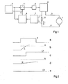
- an electric motor 1 is over two lines 3, 4 connected to a power output stage 2, which is preferably operated in push-pull, for which purpose in one Control unit 5 pulse width modulated pulses via a driver 6 of the final stage 2 are supplied.
- a current measuring resistor 12 is inserted in line 4, whose voltage drop is fed to a threshold switch 7 is a signal when a predetermined threshold is reached generated for setting a bistable circuit 8.
- This bistable circuit 8 is from each positive edge of the control unit 5 generated control pulses reset.
- On Output signal C of the bistable circuit is with a control input a switch 11 and with an input of the control device 5 connected.
- the overload is due to a blockage or a special one Stiffness of the electric motor 1 causes, acts in the output circuit of the power output stage 2 additionally the inductance of the electric motor, which, for example, is 50 ⁇ H an inductance of a cable several meters long of, for example, 7 ⁇ H.
- it can be displayed or registered that it is the overload is a blocking of the motor.
Landscapes
- Engineering & Computer Science (AREA)
- Power Engineering (AREA)
- Physics & Mathematics (AREA)
- General Physics & Mathematics (AREA)
- Automation & Control Theory (AREA)
- Control Of Electric Motors In General (AREA)
Abstract
Description
- der Strom i den Schwellwert S vor dem Ende des Impulses P erreicht. Nach dem Impuls P wird dann von dem Steuergerät das Ausgangssignal C1 (Fig. 2c) abgefragt.
Claims (6)
- Verfahren zur Fehlerdiagnose an gesteuerten elektrischen Antrieben, wobei ein Elektromotor über mindestens eine Leitung an eine Leistungsendstufe angeschlossen ist und ein Steuergerät die Endstufe mit Impulsen ansteuert und wobei im Falle eines unzulässig hohen Stroms eine Notabschaltung erfolgt, dadurch gekennzeichnet, dass nach einer Notabschaltung eine Wiedereinschaltung für eine vorgegebene Dauer erfolgt, dass bei einer wiederholten Abschaltung durch unzulässig hohen Strom während der vorgegebenen Dauer ein Leitungskurzschluss erkannt wird und dass nach Ablauf der vorgegebenen Dauer ohne Notabschaltung ein Blockieren des Elektromotors erkannt wird.
- Verfahren nach Anspruch 1, dadurch gekennzeichnet, dass die vorgegebene Dauer länger als eine durch die Induktivität und den Widerstand der mindestens einen Leitung vorgegebene Zeitkonstante und kürzer als die durch die Induktivität und den Widerstand des Elektromotors bedingte Zeitkonstante ist.
- Einrichtung zur Fehlerdiagnose an gesteuerten elektrischen Antrieben, wobei ein Elektromotor (1) über mindestens eine Leitung (3, 4) an eine Leistungsendstufe (2) angeschlossen ist und ein Steuergerät (5) die Endstufe mit Impulsen ansteuert und wobei im Falle eines unzulässig hohen Stroms eine Notabschaltung erfolgt, gekennzeichnet durch Mittel zur Wiedereinschaltung nach einer Notabschaltung für eine vorgegebene Dauer, Mittel zum Erkennen eines Leitungskurzschlusses bei einer wiederholten Abschaltung durch unzulässig hohen Strom während der vorgegebenen Dauer und Mittel zum Erkennen eines Blockierens des Elektromotors nach Ablauf der vorgegebenen Dauer ohne Notabschaltung.
- Einrichtung nach Anspruch 3, dadurch gekennzeichnet, dass die vorgegebene Dauer länger als eine durch die Induktivität und den Widerstand der mindestens einen Leitung vorgegebene Zeitkonstante und kürzer als die durch die Induktivität und den Widerstand des Elektromotors bedingte Zeitkonstante ist.
- Einrichtung nach einem der Ansprüche 3 oder 4, dadurch gekennzeichnet, dass das Steuergerät (5) eine programmierbare Einrichtung umfasst und dass zusätzlich eine mit einer Strommesseinrichtung (12) verbundene Abschalteinrichtung (7, 8) zur Unterbrechung der Zuleitung der Impulse vom Steuergerät (5) zur Leistungsendstufe (2) und zur Meldung der Unterbrechung an die programmierbare Einrichtung (5) vorgesehen ist.
- Einrichtung nach Anspruch 5, dadurch gekennzeichnet, dass die Abschalteinrichtung aus einer bistabilen Schaltung (8) besteht, die von dem Impuls rückgesetzt und bei Überschreiten eines vorgegebenen Strompegels gesetzt wird.
Applications Claiming Priority (2)
| Application Number | Priority Date | Filing Date | Title |
|---|---|---|---|
| DE10204039A DE10204039A1 (de) | 2002-02-01 | 2002-02-01 | Verfahren und Einrichtung zur Fehlerdiagnose an gesteuerten elektrischen Antrieben |
| DE10204039 | 2002-02-01 |
Publications (3)
| Publication Number | Publication Date |
|---|---|
| EP1333346A2 true EP1333346A2 (de) | 2003-08-06 |
| EP1333346A3 EP1333346A3 (de) | 2006-07-12 |
| EP1333346B1 EP1333346B1 (de) | 2010-07-28 |
Family
ID=7713520
Family Applications (1)
| Application Number | Title | Priority Date | Filing Date |
|---|---|---|---|
| EP03001638A Expired - Lifetime EP1333346B1 (de) | 2002-02-01 | 2003-01-24 | Verfahren und Einrichtung zur Fehlerdiagnose an gesteuerten elektrischen Antrieben |
Country Status (2)
| Country | Link |
|---|---|
| EP (1) | EP1333346B1 (de) |
| DE (2) | DE10204039A1 (de) |
Families Citing this family (1)
| Publication number | Priority date | Publication date | Assignee | Title |
|---|---|---|---|---|
| AT503105B1 (de) * | 2006-07-17 | 2007-08-15 | Rohregger Herbert | Einsatz für ein kochgeschirr |
Citations (1)
| Publication number | Priority date | Publication date | Assignee | Title |
|---|---|---|---|---|
| DE19858697A1 (de) | 1998-12-18 | 2000-07-27 | Mannesmann Vdo Ag | Verfahren und Schaltungsanordnung zur Überwachung des Betriebszustandes einer Last |
Family Cites Families (4)
| Publication number | Priority date | Publication date | Assignee | Title |
|---|---|---|---|---|
| DE3305183A1 (de) * | 1983-02-15 | 1984-08-16 | Robert Bosch Gmbh, 7000 Stuttgart | Schutzschaltung gegen ueberstrom |
| DE4115295A1 (de) * | 1991-05-10 | 1992-11-12 | Telefunken Electronic Gmbh | Schaltungsanordnung zur steuerung und ueberwachung eines laststromes |
| US6239960B1 (en) * | 1998-04-03 | 2001-05-29 | Basler Electric Company | Reconfigurable reclosing relay |
| DE19837796A1 (de) * | 1998-08-20 | 2000-02-24 | Wilo Gmbh | Verfahren zur Ermittlung des Pumpenzustandes |
-
2002
- 2002-02-01 DE DE10204039A patent/DE10204039A1/de not_active Withdrawn
-
2003
- 2003-01-24 EP EP03001638A patent/EP1333346B1/de not_active Expired - Lifetime
- 2003-01-24 DE DE50312920T patent/DE50312920D1/de not_active Expired - Lifetime
Patent Citations (1)
| Publication number | Priority date | Publication date | Assignee | Title |
|---|---|---|---|---|
| DE19858697A1 (de) | 1998-12-18 | 2000-07-27 | Mannesmann Vdo Ag | Verfahren und Schaltungsanordnung zur Überwachung des Betriebszustandes einer Last |
Also Published As
| Publication number | Publication date |
|---|---|
| DE10204039A1 (de) | 2003-08-14 |
| EP1333346B1 (de) | 2010-07-28 |
| EP1333346A3 (de) | 2006-07-12 |
| DE50312920D1 (de) | 2010-09-09 |
Similar Documents
| Publication | Publication Date | Title |
|---|---|---|
| DE19614354C2 (de) | Steuerschaltung für eine MOS-Gate-gesteuerte Leistungshalbleiterschaltung | |
| EP2519960B1 (de) | Vorrichtung zur elektrischen stromkreisüberwachung, schaltungsanordnung zur versorgung eines verbrauchers und verfahren zum betreiben einer schaltungsanordnung | |
| DE102004018966B4 (de) | Reihenschlussmotor | |
| EP2208215B1 (de) | Schaltanordnung und verfahren zum ansteuern eines elektromagnetischen relais | |
| DE19500452B4 (de) | Verfahren und Vorrichtung zur Überwachung der Funktionsfähigkeit eines Leerlaufstellers | |
| EP2017867A2 (de) | Dreiphasige Leistungsendstufe | |
| DE102016100498A1 (de) | Leistungsschaltvorrichtung | |
| DE102016107598B3 (de) | Vorrichtung und verfahren zum überwachen eines hochvolt-schützes in einem fahrzeug | |
| DE102010064258B4 (de) | Halbleiterbauelement mit Überstromschutz | |
| DE102011107734B4 (de) | Schaltungsanordnung zum Schalten eines Relais in einen sicheren Schaltzustand | |
| EP4012926B1 (de) | Gleichstromschalter | |
| EP3696558A1 (de) | Vorrichtung und verfahren zur automatischen prüfung eines schaltorgans | |
| DE112016005736B4 (de) | Fahrzeugsteuervorrichtung | |
| DE102009045220B4 (de) | System und Verfahren zum Begrenzen von Stromoszillationen | |
| WO2015121085A1 (de) | Verfahren und vorrichtung zum messen eines batteriezellenstromes | |
| WO2008116676A1 (de) | Fehlererkennung in einem steuergerät | |
| EP1973014B1 (de) | Einrichtung und Verfahren zur automatischen Erkennung und Unterscheidung von an eine zweikanalige Sicherheitskombination angeschlossenen ein- oder zweikanaligen elektronischen Sensoren | |
| EP0945950A2 (de) | Verfahren und Vorrichtung zur Ansteuerung eines Verbrauchers | |
| EP1333346B1 (de) | Verfahren und Einrichtung zur Fehlerdiagnose an gesteuerten elektrischen Antrieben | |
| EP1994620B1 (de) | Schutzeinrichtung und verfahren zum überwachen der gerätetemperatur eines gerätes | |
| DE102020108878A1 (de) | Schutzschaltung mit Halbleiterschalter, Verfahren zum Betreiben eines Halbleiterschalters, Hochvoltbordnetz sowie Kraftfahrzeug | |
| DE102019131192A1 (de) | Schutzschaltung mit Leistungshalbleiterschalter für ein Hochvoltbordnetz, Verfahren zum Betreiben eines Leistungshalbleiterschalters, Hochvoltbordnetz sowie Kraftfahrzeug | |
| EP1906534B1 (de) | Verfahren zum Bestimmen einer Einschaltschwelle und elektronische Schaltungsanordnung zur Durchführung des Verfahrens | |
| DE112011101763T5 (de) | Fehlerschutzschaltung für eine IEC-61158-Feldbus-Abzweigleitung und Verfahren zu deren Anwendung | |
| DE2823708C2 (de) | Anordnung zur zeitmultiplexen Datenübertragung mit einem Bus-System |
Legal Events
| Date | Code | Title | Description |
|---|---|---|---|
| PUAI | Public reference made under article 153(3) epc to a published international application that has entered the european phase |
Free format text: ORIGINAL CODE: 0009012 |
|
| AK | Designated contracting states |
Designated state(s): AT BE BG CH CY CZ DE DK EE ES FI FR GB GR HU IE IT LI LU MC NL PT SE SI SK TR |
|
| AX | Request for extension of the european patent |
Extension state: AL LT LV MK RO |
|
| PUAL | Search report despatched |
Free format text: ORIGINAL CODE: 0009013 |
|
| AK | Designated contracting states |
Kind code of ref document: A3 Designated state(s): AT BE BG CH CY CZ DE DK EE ES FI FR GB GR HU IE IT LI LU MC NL PT SE SI SK TR |
|
| AX | Request for extension of the european patent |
Extension state: AL LT LV MK RO |
|
| RIC1 | Information provided on ipc code assigned before grant |
Ipc: G05B 9/02 20060101AFI20030514BHEP Ipc: H02H 7/08 20060101ALI20060606BHEP |
|
| 17P | Request for examination filed |
Effective date: 20061214 |
|
| AKX | Designation fees paid |
Designated state(s): DE FR GB IT |
|
| RAP1 | Party data changed (applicant data changed or rights of an application transferred) |
Owner name: CONTINENTAL AUTOMOTIVE GMBH |
|
| 17Q | First examination report despatched |
Effective date: 20081015 |
|
| GRAP | Despatch of communication of intention to grant a patent |
Free format text: ORIGINAL CODE: EPIDOSNIGR1 |
|
| GRAS | Grant fee paid |
Free format text: ORIGINAL CODE: EPIDOSNIGR3 |
|
| GRAA | (expected) grant |
Free format text: ORIGINAL CODE: 0009210 |
|
| AK | Designated contracting states |
Kind code of ref document: B1 Designated state(s): DE FR GB IT |
|
| REG | Reference to a national code |
Ref country code: GB Ref legal event code: FG4D Free format text: NOT ENGLISH |
|
| REF | Corresponds to: |
Ref document number: 50312920 Country of ref document: DE Date of ref document: 20100909 Kind code of ref document: P |
|
| PLBE | No opposition filed within time limit |
Free format text: ORIGINAL CODE: 0009261 |
|
| STAA | Information on the status of an ep patent application or granted ep patent |
Free format text: STATUS: NO OPPOSITION FILED WITHIN TIME LIMIT |
|
| 26N | No opposition filed |
Effective date: 20110429 |
|
| REG | Reference to a national code |
Ref country code: DE Ref legal event code: R097 Ref document number: 50312920 Country of ref document: DE Effective date: 20110429 |
|
| REG | Reference to a national code |
Ref country code: FR Ref legal event code: PLFP Year of fee payment: 13 |
|
| PGFP | Annual fee paid to national office [announced via postgrant information from national office to epo] |
Ref country code: IT Payment date: 20150130 Year of fee payment: 13 Ref country code: DE Payment date: 20150131 Year of fee payment: 13 |
|
| PGFP | Annual fee paid to national office [announced via postgrant information from national office to epo] |
Ref country code: FR Payment date: 20150122 Year of fee payment: 13 Ref country code: GB Payment date: 20150121 Year of fee payment: 13 |
|
| REG | Reference to a national code |
Ref country code: DE Ref legal event code: R119 Ref document number: 50312920 Country of ref document: DE |
|
| GBPC | Gb: european patent ceased through non-payment of renewal fee |
Effective date: 20160124 |
|
| REG | Reference to a national code |
Ref country code: FR Ref legal event code: ST Effective date: 20160930 |
|
| PG25 | Lapsed in a contracting state [announced via postgrant information from national office to epo] |
Ref country code: GB Free format text: LAPSE BECAUSE OF NON-PAYMENT OF DUE FEES Effective date: 20160124 Ref country code: DE Free format text: LAPSE BECAUSE OF NON-PAYMENT OF DUE FEES Effective date: 20160802 |
|
| PG25 | Lapsed in a contracting state [announced via postgrant information from national office to epo] |
Ref country code: FR Free format text: LAPSE BECAUSE OF NON-PAYMENT OF DUE FEES Effective date: 20160201 |
|
| PG25 | Lapsed in a contracting state [announced via postgrant information from national office to epo] |
Ref country code: IT Free format text: LAPSE BECAUSE OF NON-PAYMENT OF DUE FEES Effective date: 20160124 |