EP1333537A1 - Steckverbinderanordnung für ein standardisiertes elektrisches oder optisches Kabel - Google Patents
Steckverbinderanordnung für ein standardisiertes elektrisches oder optisches Kabel Download PDFInfo
- Publication number
- EP1333537A1 EP1333537A1 EP03290164A EP03290164A EP1333537A1 EP 1333537 A1 EP1333537 A1 EP 1333537A1 EP 03290164 A EP03290164 A EP 03290164A EP 03290164 A EP03290164 A EP 03290164A EP 1333537 A1 EP1333537 A1 EP 1333537A1
- Authority
- EP
- European Patent Office
- Prior art keywords
- plug
- cord
- adapter
- cable gland
- gland
- Prior art date
- Legal status (The legal status is an assumption and is not a legal conclusion. Google has not performed a legal analysis and makes no representation as to the accuracy of the status listed.)
- Granted
Links
- 230000003287 optical effect Effects 0.000 title claims description 20
- 210000004907 gland Anatomy 0.000 claims description 34
- 230000006835 compression Effects 0.000 claims description 5
- 238000007906 compression Methods 0.000 claims description 5
- 238000012856 packing Methods 0.000 claims 1
- 208000031968 Cadaver Diseases 0.000 description 12
- 230000008901 benefit Effects 0.000 description 4
- 238000003780 insertion Methods 0.000 description 3
- 230000037431 insertion Effects 0.000 description 3
- PXHVJJICTQNCMI-UHFFFAOYSA-N Nickel Chemical compound [Ni] PXHVJJICTQNCMI-UHFFFAOYSA-N 0.000 description 2
- 229910000925 Cd alloy Inorganic materials 0.000 description 1
- 229910000990 Ni alloy Inorganic materials 0.000 description 1
- 230000005540 biological transmission Effects 0.000 description 1
- 238000010276 construction Methods 0.000 description 1
- 230000009849 deactivation Effects 0.000 description 1
- 238000012217 deletion Methods 0.000 description 1
- 230000037430 deletion Effects 0.000 description 1
- 230000001419 dependent effect Effects 0.000 description 1
- 230000002542 deteriorative effect Effects 0.000 description 1
- 238000010616 electrical installation Methods 0.000 description 1
- 239000000835 fiber Substances 0.000 description 1
- 238000009776 industrial production Methods 0.000 description 1
- 239000011810 insulating material Substances 0.000 description 1
- 239000012212 insulator Substances 0.000 description 1
- 239000007788 liquid Substances 0.000 description 1
- 238000004519 manufacturing process Methods 0.000 description 1
- 230000002093 peripheral effect Effects 0.000 description 1
- 230000035939 shock Effects 0.000 description 1
- 230000001629 suppression Effects 0.000 description 1
Images


Classifications
-
- H—ELECTRICITY
- H01—ELECTRIC ELEMENTS
- H01R—ELECTRICALLY-CONDUCTIVE CONNECTIONS; STRUCTURAL ASSOCIATIONS OF A PLURALITY OF MUTUALLY-INSULATED ELECTRICAL CONNECTING ELEMENTS; COUPLING DEVICES; CURRENT COLLECTORS
- H01R13/00—Details of coupling devices of the kinds covered by groups H01R12/70 or H01R24/00 - H01R33/00
- H01R13/46—Bases; Cases
- H01R13/516—Means for holding or embracing insulating body, e.g. casing, hoods
Definitions
- the subject of the present invention is a plug device for a standard electrical or optical connection cord provided with at least one of its ends of a plug having a body provided with a lock external mechanical.
- Ethernet which is a network already used in the world of office automation to connect computers and peripherals these meet these conditions.
- the connection used is called the RJ45.
- This connection consists of a shielded or unshielded cord standard at the ends of which plugs are also mounted standard with a body fitted with an external mechanical lock which can be retracted by a pressure action on the end of the lock. This lock is of course used for mechanical fixing during connection with a base.
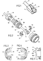
- cord 10 and its plug 12 which has a body 14 generally overmolded on the cord 10.
- a mechanical lock 16 is provided which can be brought into non-active position by a tongue 18 forming a control lever.
- connection meets the conditions of the Ethernet standard, it is not at all suitable for the environment of industrial production in which projections of liquid, shocks, untimely pulls on the cord, vibrations, electromagnetic disturbances, etc.
- the cords of RJ45 or RJ11 connection have the additional advantage that they are today standard cords already calibrated with, at their ends, two RJ45 or RJ11 plugs overmolded at the end of the cord.
- a solution to adapt RJ45 connectors to requirements linked to the industrial environment would consist in separating the cord standard sheets and replace these with type sheets used in an industrial environment.
- the plug adapter is shaped so that it maintains the mechanical lock of the cord plug in the inactive position.
- the connection between the plug and the corresponding base is made of classic way simply by the plug body.
- said plug adapter insulator consists of two separate parts, each defining a part of the internal profile capable of receiving said body of the cord plug, whereby the two parts of said adapter can be put in place successively on the body of the cord plug.
- the assembly of the cord plug in the insulating adapter is easy since each of the pieces can be placed successively according to a lateral direction relative to the body of the cord plug.
- each piece of the plug adapter has a relief forming a stop capable of cooperating with part of the cord plug lock when said lock is in the inactive position.
- Figures 2 to 8 illustrate the construction of the plug body for an electric cord, preferably.
- plug body 20 It includes a plug body 20, a plug adapter 22 for plug 10 of the cord, which preferably consists of two separate parts 24 and 26, a connecting part 28 and a body of cable gland 30 fitted with a cylindrical cable gland 32.
- the plug body 20 can have any shape and internally comprises means for axially and radially securing the plug adapter 22. It further comprises means by bayonet of connection to a base body not shown.
- the plug body 20 further comprises at its rear part 20a a thread.
- the connecting piece 28 has a front part 28a and a rear part 28b provided with reverse threads 34 and 36.
- the gland body 30 includes a thread 38 and a rear wall 40 pierced with an axial opening of sufficient dimensions to allow passage of the plug 12 of the cord 10.
- the connecting piece 28 and the cable gland 32 has sufficient axial passage to allow the passage of the plug 12 of the cord 10.
- the adapter 22 can be made of an insulating material possibly metallized with a nickel or cadmium alloy for the electro-magnetic protection.
- the parts 24 and 26 forming the adapter 22 can be joined together by clipping members 42 and 44.
- Each part 24, 26 has internal profiles 24a, 24b, which, once both assembled parts, define a recess 46 for receiving the body of plug 12 surmounted by a groove 48 intended to receive the lever control 18 of the plug 12 when the latter is in the lowered position corresponding to deactivation of latch 16.
- each piece 26 (24) has on its front face 26b (24b) an extension 50 in the form of beam protruding from the anterior face.
- the extensions 50 are positioned so that when the body 14 of the plug 12 is introduced into the recess 46 of the adapter 22 and when the latch 16 is in the deactivated position, the ends 50a of the extensions 50 are in stop against the locks 16. This is best shown in FIG. 6.
- the connecting piece 28, the cable gland 32 and the body of cable gland 30 are engaged in the cord 10 beyond the plug 12 as shown in Figure 2.
- the part 26 is mounted the adapter 22.
- the second part 24 of the adapter is mounted on the plug body 14, which simultaneously causes the locking of the parts 24 and 26.
- the adapter 22 is then fixed on the body 14 of the plug 12, as shown in Figure 7.
- the plug 12 and the adapter 22 are introduced into the plug body 20.
- the external wall 24c, 26c of the adapter has a boss and the internal wall 20b of the plug body 20 has four notches offset by 90 degrees.
- the adapter 22 is thus immobilized in rotation in the plug body 20 and it can occupy one of four coding positions.
- the workpiece link 28 is screwed onto the plug body 20, which immobilizes translation of the adapter 22 relative to the plug body.
- the body of cable gland 30 is screwed onto the thread 36 of the connecting piece, which causes compression of the cable gland 32 and tightening of it on the cord 10.
- the sheet 12 is immobilized in translation relative to the adapter 22 because the ends 50a of the extensions 50 of the adapter 22 abuts on the latch 16 in position disabled.
- the latch 16 has standardized standard dimensions. The device plug according to the invention can therefore be used with all cords including the files include a lock conforming to this standard.
- the connecting piece 28 is provided on its second end of an O-ring capable of cooperating with said body gland.
- the optical cord 60 has its end which is mounted on a cord plug body 62 and secured thereto by a ferrule 64.
- the cord plug body has a latch on its outer face mechanical 64 which will be described later in more detail.
- the plug device itself comprises first of all a plug body 66 fitted on its external face with a fixing nut 67 with the combined optical connection element.
- the plug device also includes a plug adapter 68, 70 for mounting in the plug body 66.
- the plug device also includes a tubular connection piece 72, a first end of which is intended to be made integral with the plug body 66 and the other end of which 72b is intended to be secured to a cable gland not shown on the figure.
- the plug body 66 comprises, in its internal face 66a a shoulder 74 able to cooperate with a conjugated shoulder 76 formed in the external face of the adapter 70, in order to immobilize the latter in forward translation.
- the adapter 70 can be immobilized in the plug body 66 by putting in place of a mechanical locking system in translation 78.
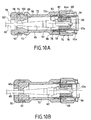
- the adapter 70 has a axial recess 80 whose contour allows the insertion of the end of the cord plug body 62a. This profile also defines a groove upper 80 to allow the passage of the mechanical lock 64 of the plug body of the optical cord. More specifically, as shown in the FIG. 10A, the end of the latch 64 has a projection 64a which can cooperate with a shoulder 82 formed in the axial passage 80 of the adapter. The cooperation of the projection 64a and the shoulder 82 allows the attachment of the plug body 62 of the cord with the adapter. It is necessary add that the shoulder 82 defines a profile such that the latch 64 is held in its disabled position.
- the connecting piece 72 has, at its first end 72a, a thread capable of cooperating with a thread 86 formed at the end rear of the plug body 66.
- the second end 72b of the piece of link 72 defines a housing 88 of increased diameter and a shoulder 90 intended to receive a cable gland 92.
- This cable gland 92 at rest, as shown in FIG. 10A, has an axial passage 94 allowing the free passage of the plug body 62 of the optical cord.
- the plug device comprises, finally, a tightening nut 96, the internal thread 98 can cooperate with an external thread 100 provided for the end 72b of the connecting piece 72.
- This nut 76 has an orifice axial 102 whose diameter, or more generally the dimensions are sufficient to allow free passage of the plug body 62 of the cord optical.
- the use of the plug device intended to be mounted on the plug 62 of the optical cord 60 is as follows. At first, the connecting piece 72, the cable gland 92 and the clamping nut 96 are wound up around the optical cord 66. Then, the front part 62a of the body plug 62 is engaged in the axial passage 80 of the adapter 70, the mechanical lock 64 being lowered to the inactive position. After insertion of the cord plug body in the adapter 70, the lock 64, thanks to its projecting part 64a cooperating with the shoulder 62, ensures the securing the cord plug body and the adapter. This set is placed in the plug body 70 and immobilized by the insertion of the translational locking device 78.
Landscapes
- Connector Housings Or Holding Contact Members (AREA)
- Mechanical Coupling Of Light Guides (AREA)
- Details Of Connecting Devices For Male And Female Coupling (AREA)
- Coupling Device And Connection With Printed Circuit (AREA)
- Communication Cables (AREA)
- Optical Couplings Of Light Guides (AREA)
Applications Claiming Priority (4)
| Application Number | Priority Date | Filing Date | Title |
|---|---|---|---|
| FR0201321 | 2002-02-05 | ||
| FR0201321A FR2835658B1 (fr) | 2002-02-05 | 2002-02-05 | Dispositif de fiche pour un cordon standard de liaison electrique |
| FR0215512 | 2002-12-09 | ||
| FR0215512A FR2835657B1 (fr) | 2002-02-05 | 2002-12-09 | Dispositif de fiche pour un cordon standard de liaison electrique ou optique |
Publications (2)
| Publication Number | Publication Date |
|---|---|
| EP1333537A1 true EP1333537A1 (de) | 2003-08-06 |
| EP1333537B1 EP1333537B1 (de) | 2005-04-13 |
Family
ID=26213332
Family Applications (1)
| Application Number | Title | Priority Date | Filing Date |
|---|---|---|---|
| EP03290164A Expired - Lifetime EP1333537B1 (de) | 2002-02-05 | 2003-01-23 | Steckverbinderanordnung für ein standardisiertes elektrisches oder optisches Kabel |
Country Status (7)
| Country | Link |
|---|---|
| EP (1) | EP1333537B1 (de) |
| JP (1) | JP4267932B2 (de) |
| AT (1) | ATE293298T1 (de) |
| CA (1) | CA2418376C (de) |
| DE (1) | DE60300484T2 (de) |
| ES (1) | ES2242146T3 (de) |
| FR (1) | FR2835657B1 (de) |
Cited By (14)
| Publication number | Priority date | Publication date | Assignee | Title |
|---|---|---|---|---|
| WO2005026799A1 (en) * | 2003-09-08 | 2005-03-24 | Adc Telecommunications, Inc. | Ruggedized fiber optic connection |
| FR2906089A1 (fr) * | 2006-09-18 | 2008-03-21 | Legrand France | Capot pour fiche predeterminee de reseau d'information, ensemble et systeme le comportant |
| EP1566674B1 (de) * | 2004-02-19 | 2009-05-06 | Reichle & De-Massari AG | Steckergehäuse eines optischen Steckverbinders für die industrielle Umgebung |
| US7572065B2 (en) | 2007-01-24 | 2009-08-11 | Adc Telecommunications, Inc. | Hardened fiber optic connector |
| US7591595B2 (en) | 2007-01-24 | 2009-09-22 | Adc Telelcommunications, Inc. | Hardened fiber optic adapter |
| US7614797B2 (en) | 2007-01-24 | 2009-11-10 | Adc Telecommunications, Inc. | Fiber optic connector mechanical interface converter |
| US7677814B2 (en) | 2007-05-06 | 2010-03-16 | Adc Telecommunications, Inc. | Mechanical interface converter for making non-ruggedized fiber optic connectors compatible with a ruggedized fiber optic adapter |
| US7686519B2 (en) | 2007-06-18 | 2010-03-30 | Adc Telecommunications, Inc. | Hardened fiber optic housing and cable assembly |
| US7722258B2 (en) | 2007-05-06 | 2010-05-25 | Adc Telecommunications, Inc. | Interface converter for SC fiber optic connectors |
| US7744286B2 (en) | 2007-12-11 | 2010-06-29 | Adc Telecommunications, Inc. | Hardened fiber optic connection system with multiple configurations |
| CN105870698A (zh) * | 2016-05-16 | 2016-08-17 | 苏州博豪精密机械有限公司 | 一种插头圆盘壳体 |
| EP3106904A1 (de) * | 2015-06-16 | 2016-12-21 | Nexans | Lichtleitfaser-steckverbindervorrichtung |
| US10444443B2 (en) | 2013-06-27 | 2019-10-15 | CommScope Connectivity Belgium BVBA | Fiber optic cable anchoring device for use with fiber optic connectors and methods of using the same |
| CN116191113A (zh) * | 2022-11-26 | 2023-05-30 | 中航光电科技股份有限公司 | 一种具备浮动连接功能的线缆组件 |
Families Citing this family (11)
| Publication number | Priority date | Publication date | Assignee | Title |
|---|---|---|---|---|
| CN100364182C (zh) * | 2005-04-12 | 2008-01-23 | 中航光电科技股份有限公司 | 小体积快速分离rj-45电连接器 |
| JP4771523B2 (ja) * | 2005-08-18 | 2011-09-14 | 株式会社三桂製作所 | フード |
| DE202006011910U1 (de) * | 2005-11-09 | 2007-03-22 | Weidmüller Interface GmbH & Co. KG | Adapter zur Aufnahme eines Steckerteiles |
| DE102007018389B4 (de) * | 2007-04-17 | 2012-01-12 | Mc Technology Gmbh | Steckverbinder |
| JP5892600B2 (ja) * | 2012-05-22 | 2016-03-23 | 日本航空電子工業株式会社 | コネクタ装置 |
| JP5866734B2 (ja) | 2012-12-27 | 2016-02-17 | ヒロセ電機株式会社 | コネクタ、このコネクタを用いたコネクタ装置、及びこのコネクタに用いるコネクタ部材 |
| CN103594862A (zh) * | 2013-11-25 | 2014-02-19 | 济南中维世纪科技有限公司 | 摄像机尾线连接器 |
| EP2960695B1 (de) * | 2014-06-24 | 2020-08-12 | TE Connectivity Nederland B.V. | Verbinder für ein Kabel und Verbinderanordnung |
| US9450338B2 (en) * | 2014-08-06 | 2016-09-20 | Molex, Llc | High speed connector with ruggedized exterior structure and shielding |
| JP6805408B2 (ja) * | 2015-10-30 | 2020-12-23 | 群馬県 | 燃料電池を用いた発電装置及び発電方法 |
| KR102395601B1 (ko) * | 2021-09-13 | 2022-05-10 | 주식회사유비씨에스 | 전기 케이블용 방수 어셈블리 |
Citations (3)
| Publication number | Priority date | Publication date | Assignee | Title |
|---|---|---|---|---|
| FR1409281A (fr) * | 1964-05-06 | 1965-08-27 | Connecteur pour câbles coaxiaux et câbles blindés à un ou plusieurs conducteurs | |
| US6257923B1 (en) * | 2000-02-03 | 2001-07-10 | Phillips & Temro Industries Inc. | Dual media connector for a vehicle |
| WO2001057965A1 (en) * | 2000-02-03 | 2001-08-09 | Matsushita Electric Industrial Co., Ltd. | Cable connector |
-
2002
- 2002-12-09 FR FR0215512A patent/FR2835657B1/fr not_active Expired - Lifetime
-
2003
- 2003-01-23 EP EP03290164A patent/EP1333537B1/de not_active Expired - Lifetime
- 2003-01-23 ES ES03290164T patent/ES2242146T3/es not_active Expired - Lifetime
- 2003-01-23 AT AT03290164T patent/ATE293298T1/de active
- 2003-01-23 DE DE60300484T patent/DE60300484T2/de not_active Expired - Lifetime
- 2003-02-04 CA CA2418376A patent/CA2418376C/en not_active Expired - Lifetime
- 2003-02-04 JP JP2003026654A patent/JP4267932B2/ja not_active Expired - Lifetime
Patent Citations (3)
| Publication number | Priority date | Publication date | Assignee | Title |
|---|---|---|---|---|
| FR1409281A (fr) * | 1964-05-06 | 1965-08-27 | Connecteur pour câbles coaxiaux et câbles blindés à un ou plusieurs conducteurs | |
| US6257923B1 (en) * | 2000-02-03 | 2001-07-10 | Phillips & Temro Industries Inc. | Dual media connector for a vehicle |
| WO2001057965A1 (en) * | 2000-02-03 | 2001-08-09 | Matsushita Electric Industrial Co., Ltd. | Cable connector |
Cited By (37)
| Publication number | Priority date | Publication date | Assignee | Title |
|---|---|---|---|---|
| WO2005026799A1 (en) * | 2003-09-08 | 2005-03-24 | Adc Telecommunications, Inc. | Ruggedized fiber optic connection |
| US6962445B2 (en) | 2003-09-08 | 2005-11-08 | Adc Telecommunications, Inc. | Ruggedized fiber optic connection |
| USRE42522E1 (en) | 2003-09-08 | 2011-07-05 | Adc Telecommunications, Inc. | Ruggedized fiber optic connection |
| EP1566674B1 (de) * | 2004-02-19 | 2009-05-06 | Reichle & De-Massari AG | Steckergehäuse eines optischen Steckverbinders für die industrielle Umgebung |
| FR2906089A1 (fr) * | 2006-09-18 | 2008-03-21 | Legrand France | Capot pour fiche predeterminee de reseau d'information, ensemble et systeme le comportant |
| WO2008034961A1 (fr) * | 2006-09-18 | 2008-03-27 | Legrand France | Capot pour fiche predeterminee de reseau d'information, ensemble et systeme le comportant |
| US11409057B2 (en) | 2007-01-24 | 2022-08-09 | Commscope Technologies Llc | Hardened fiber optic connector |
| US7614797B2 (en) | 2007-01-24 | 2009-11-10 | Adc Telecommunications, Inc. | Fiber optic connector mechanical interface converter |
| US7591595B2 (en) | 2007-01-24 | 2009-09-22 | Adc Telelcommunications, Inc. | Hardened fiber optic adapter |
| US12111502B2 (en) | 2007-01-24 | 2024-10-08 | Commscope Technologies Llc | Hardened fiber optic connector |
| US10877224B2 (en) | 2007-01-24 | 2020-12-29 | Commscope Technologies Llc | Fiber optic adapter |
| US9664862B2 (en) | 2007-01-24 | 2017-05-30 | Commscope Technologies Llc | Hardened fiber optic connector |
| US8770862B2 (en) | 2007-01-24 | 2014-07-08 | Adc Telecommunications, Inc. | Hardened fiber optic connector |
| US7572065B2 (en) | 2007-01-24 | 2009-08-11 | Adc Telecommunications, Inc. | Hardened fiber optic connector |
| US7677814B2 (en) | 2007-05-06 | 2010-03-16 | Adc Telecommunications, Inc. | Mechanical interface converter for making non-ruggedized fiber optic connectors compatible with a ruggedized fiber optic adapter |
| US7722258B2 (en) | 2007-05-06 | 2010-05-25 | Adc Telecommunications, Inc. | Interface converter for SC fiber optic connectors |
| US8137002B2 (en) | 2007-05-06 | 2012-03-20 | Adc Telecommunications, Inc. | Mechanical interface converter for making non-ruggedized fiber optic connectors compatible with a ruggedized fiber optic adapter |
| US8128294B2 (en) | 2007-05-06 | 2012-03-06 | Adc Telecommunications, Inc. | Interface converter for SC fiber optic connectors |
| US7686519B2 (en) | 2007-06-18 | 2010-03-30 | Adc Telecommunications, Inc. | Hardened fiber optic housing and cable assembly |
| US10101538B2 (en) | 2007-12-11 | 2018-10-16 | Commscope Technologies Llc | Hardened fiber optic connector compatible with hardened and non-hardened fiber optic adapters |
| US7744288B2 (en) | 2007-12-11 | 2010-06-29 | Adc Telecommunications, Inc. | Hardened fiber optic connector compatible with hardened and non-hardened fiber optic adapters |
| US7959361B2 (en) | 2007-12-11 | 2011-06-14 | Adc Telecommunications, Inc. | Hardened fiber optic connection system |
| US12181718B2 (en) | 2007-12-11 | 2024-12-31 | Commscope Technologies Llc | Hardened fiber optic connector compatible with hardened and non-hardened fiber optic adapters |
| US9482829B2 (en) | 2007-12-11 | 2016-11-01 | Commscope Technologies Llc | Hardened fiber optic connector compatible with hardened and non-hardened fiber optic adapters |
| US7744286B2 (en) | 2007-12-11 | 2010-06-29 | Adc Telecommunications, Inc. | Hardened fiber optic connection system with multiple configurations |
| US11867950B2 (en) | 2007-12-11 | 2024-01-09 | Commscope Technologies Llc | Hardened fiber optic connector compatible with hardened and non-hardened fiber optic adapters |
| US7942590B2 (en) | 2007-12-11 | 2011-05-17 | Adc Telecommunications, Inc. | Hardened fiber optic connector and cable assembly with multiple configurations |
| US8414196B2 (en) | 2007-12-11 | 2013-04-09 | Adc Telecommunications, Inc. | Optical fiber connection system with locking member |
| US10746939B2 (en) | 2007-12-11 | 2020-08-18 | Commscope Technologies Llc | Hardened fiber optic connector compatible with hardened and non-hardened fiber optic adapters |
| US8202008B2 (en) | 2007-12-11 | 2012-06-19 | Adc Telecommunications, Inc. | Hardened fiber optic connection system with multiple configurations |
| US7762726B2 (en) | 2007-12-11 | 2010-07-27 | Adc Telecommunications, Inc. | Hardened fiber optic connection system |
| US11275220B2 (en) | 2007-12-11 | 2022-03-15 | Commscope Technologies Llc | Hardened fiber optic connector compatible with hardened and non-hardened fiber optic adapters |
| US10444443B2 (en) | 2013-06-27 | 2019-10-15 | CommScope Connectivity Belgium BVBA | Fiber optic cable anchoring device for use with fiber optic connectors and methods of using the same |
| FR3037666A1 (fr) * | 2015-06-16 | 2016-12-23 | Nexans | Dispositif de connecteur de fibre optique |
| EP3106904A1 (de) * | 2015-06-16 | 2016-12-21 | Nexans | Lichtleitfaser-steckverbindervorrichtung |
| CN105870698A (zh) * | 2016-05-16 | 2016-08-17 | 苏州博豪精密机械有限公司 | 一种插头圆盘壳体 |
| CN116191113A (zh) * | 2022-11-26 | 2023-05-30 | 中航光电科技股份有限公司 | 一种具备浮动连接功能的线缆组件 |
Also Published As
| Publication number | Publication date |
|---|---|
| JP4267932B2 (ja) | 2009-05-27 |
| CA2418376C (en) | 2010-10-26 |
| JP2003243108A (ja) | 2003-08-29 |
| FR2835657B1 (fr) | 2004-08-06 |
| FR2835657A1 (fr) | 2003-08-08 |
| ATE293298T1 (de) | 2005-04-15 |
| DE60300484D1 (de) | 2005-05-19 |
| ES2242146T3 (es) | 2005-11-01 |
| CA2418376A1 (en) | 2003-08-05 |
| DE60300484T2 (de) | 2006-02-23 |
| EP1333537B1 (de) | 2005-04-13 |
Similar Documents
| Publication | Publication Date | Title |
|---|---|---|
| EP1333537B1 (de) | Steckverbinderanordnung für ein standardisiertes elektrisches oder optisches Kabel | |
| EP2239605B1 (de) | Verbindungssystem für opto-elektronische Module und Glasfasern | |
| EP2071677B1 (de) | Anschluss an Anti-Entriegelungssysteme | |
| FR2835658A1 (fr) | Dispositif de fiche pour un cordon standard de liaison electrique | |
| EP1143573A1 (de) | Koaxialer Verbinder | |
| FR2463526A1 (fr) | Connecteur de cable a armure metallique sous gaine | |
| FR2733365A1 (fr) | Assemblage de connecteur electrique a levier d'accouplement pivotant | |
| FR2756978A1 (fr) | Connecteur circulaire modulaire | |
| FR2673331A1 (fr) | Dispositif pour obturer une cavite de contact d'un connecteur electrique ou optique. | |
| EP0592287B1 (de) | Schnappverbinder für optische Fasern mit umgossenem Steckerkörper | |
| FR3053801A1 (fr) | Fiche de connexion a une embase de panneau de boitier d'equipement electronique, munie de moyens d'anti-casse de cable optique sur lequel la fiche est montee | |
| EP1111727A1 (de) | Verbindungsstecker | |
| EP2839546B1 (de) | Schnelles einwegverbindungssystem | |
| FR2638905A1 (fr) | Douille femelle multipolaire pour fiche male circulaire | |
| FR2703192A1 (fr) | Assemblage d'un connecteur à fiche et d'une prise complémentaire pour câble coaxial. | |
| FR2745122A1 (fr) | Partie male de connecteur pour circuit imprime | |
| FR2620870A1 (fr) | Dispositif de liaison separable entre une broche conductrice et au moins un fil de connexion | |
| EP0821835A1 (de) | Hinterverbindungsvorrichtung für elektrischen stecker für abgeschirmtes kabel | |
| EP0172779B1 (de) | Mehrpoliger elektrischer Verbinder | |
| EP1727245A2 (de) | Abgeschirmter Verbinder für elektrische Leiter | |
| FR2818450A1 (fr) | Fiche telemanipulable | |
| EP0895315A1 (de) | Elektrische Verbindungsanordnung | |
| FR3028356A1 (fr) | Borne de connexion electrique a vis imperdable | |
| EP0175033A1 (de) | Peritelevisionssteckverbinder | |
| EP4154360B1 (de) | Verbesserte fool-beständige vorrichtung, elektrische verbindungsanordnung mit der verbesserten fool-beständigen vorrichtung und zugehöriges montageverfahren |
Legal Events
| Date | Code | Title | Description |
|---|---|---|---|
| PUAI | Public reference made under article 153(3) epc to a published international application that has entered the european phase |
Free format text: ORIGINAL CODE: 0009012 |
|
| AK | Designated contracting states |
Designated state(s): AT BE BG CH CY CZ DE DK EE ES FI FR GB GR HU IE IT LI LU MC NL PT SE SI SK TR |
|
| AX | Request for extension of the european patent |
Extension state: AL LT LV MK RO |
|
| 17P | Request for examination filed |
Effective date: 20031211 |
|
| 17Q | First examination report despatched |
Effective date: 20040316 |
|
| AKX | Designation fees paid |
Designated state(s): AT BE BG CH CY CZ DE DK EE ES FI FR GB GR HU IE IT LI LU MC NL PT SE SI SK TR |
|
| GRAP | Despatch of communication of intention to grant a patent |
Free format text: ORIGINAL CODE: EPIDOSNIGR1 |
|
| GRAS | Grant fee paid |
Free format text: ORIGINAL CODE: EPIDOSNIGR3 |
|
| GRAA | (expected) grant |
Free format text: ORIGINAL CODE: 0009210 |
|
| AK | Designated contracting states |
Kind code of ref document: B1 Designated state(s): AT BE BG CH CY CZ DE DK EE ES FI FR GB GR HU IE IT LI LU MC NL PT SE SI SK TR |
|
| PG25 | Lapsed in a contracting state [announced via postgrant information from national office to epo] |
Ref country code: SK Free format text: LAPSE BECAUSE OF FAILURE TO SUBMIT A TRANSLATION OF THE DESCRIPTION OR TO PAY THE FEE WITHIN THE PRESCRIBED TIME-LIMIT Effective date: 20050413 Ref country code: SI Free format text: LAPSE BECAUSE OF FAILURE TO SUBMIT A TRANSLATION OF THE DESCRIPTION OR TO PAY THE FEE WITHIN THE PRESCRIBED TIME-LIMIT Effective date: 20050413 Ref country code: IE Free format text: LAPSE BECAUSE OF FAILURE TO SUBMIT A TRANSLATION OF THE DESCRIPTION OR TO PAY THE FEE WITHIN THE PRESCRIBED TIME-LIMIT Effective date: 20050413 |
|
| REG | Reference to a national code |
Ref country code: GB Ref legal event code: FG4D Free format text: NOT ENGLISH |
|
| REG | Reference to a national code |
Ref country code: CH Ref legal event code: EP |
|
| REG | Reference to a national code |
Ref country code: IE Ref legal event code: FG4D Free format text: LANGUAGE OF EP DOCUMENT: FRENCH |
|
| REF | Corresponds to: |
Ref document number: 60300484 Country of ref document: DE Date of ref document: 20050519 Kind code of ref document: P |
|
| PG25 | Lapsed in a contracting state [announced via postgrant information from national office to epo] |
Ref country code: DK Free format text: LAPSE BECAUSE OF FAILURE TO SUBMIT A TRANSLATION OF THE DESCRIPTION OR TO PAY THE FEE WITHIN THE PRESCRIBED TIME-LIMIT Effective date: 20050713 Ref country code: GR Free format text: LAPSE BECAUSE OF FAILURE TO SUBMIT A TRANSLATION OF THE DESCRIPTION OR TO PAY THE FEE WITHIN THE PRESCRIBED TIME-LIMIT Effective date: 20050713 Ref country code: BG Free format text: LAPSE BECAUSE OF FAILURE TO SUBMIT A TRANSLATION OF THE DESCRIPTION OR TO PAY THE FEE WITHIN THE PRESCRIBED TIME-LIMIT Effective date: 20050713 |
|
| PG25 | Lapsed in a contracting state [announced via postgrant information from national office to epo] |
Ref country code: HU Free format text: LAPSE BECAUSE OF FAILURE TO SUBMIT A TRANSLATION OF THE DESCRIPTION OR TO PAY THE FEE WITHIN THE PRESCRIBED TIME-LIMIT Effective date: 20050714 |
|
| REG | Reference to a national code |
Ref country code: SE Ref legal event code: TRGR |
|
| GBT | Gb: translation of ep patent filed (gb section 77(6)(a)/1977) |
Effective date: 20050802 |
|
| PG25 | Lapsed in a contracting state [announced via postgrant information from national office to epo] |
Ref country code: PT Free format text: LAPSE BECAUSE OF FAILURE TO SUBMIT A TRANSLATION OF THE DESCRIPTION OR TO PAY THE FEE WITHIN THE PRESCRIBED TIME-LIMIT Effective date: 20050913 |
|
| REG | Reference to a national code |
Ref country code: CH Ref legal event code: NV Representative=s name: MICHELI & CIE INGENIEURS-CONSEILS |
|
| REG | Reference to a national code |
Ref country code: ES Ref legal event code: FG2A Ref document number: 2242146 Country of ref document: ES Kind code of ref document: T3 |
|
| REG | Reference to a national code |
Ref country code: IE Ref legal event code: FD4D |
|
| PG25 | Lapsed in a contracting state [announced via postgrant information from national office to epo] |
Ref country code: LU Free format text: LAPSE BECAUSE OF NON-PAYMENT OF DUE FEES Effective date: 20060131 Ref country code: MC Free format text: LAPSE BECAUSE OF NON-PAYMENT OF DUE FEES Effective date: 20060131 |
|
| PLBE | No opposition filed within time limit |
Free format text: ORIGINAL CODE: 0009261 |
|
| STAA | Information on the status of an ep patent application or granted ep patent |
Free format text: STATUS: NO OPPOSITION FILED WITHIN TIME LIMIT |
|
| 26N | No opposition filed |
Effective date: 20060116 |
|
| PG25 | Lapsed in a contracting state [announced via postgrant information from national office to epo] |
Ref country code: EE Free format text: LAPSE BECAUSE OF FAILURE TO SUBMIT A TRANSLATION OF THE DESCRIPTION OR TO PAY THE FEE WITHIN THE PRESCRIBED TIME-LIMIT Effective date: 20050413 |
|
| PG25 | Lapsed in a contracting state [announced via postgrant information from national office to epo] |
Ref country code: CY Free format text: LAPSE BECAUSE OF FAILURE TO SUBMIT A TRANSLATION OF THE DESCRIPTION OR TO PAY THE FEE WITHIN THE PRESCRIBED TIME-LIMIT Effective date: 20050413 |
|
| REG | Reference to a national code |
Ref country code: FR Ref legal event code: PLFP Year of fee payment: 14 |
|
| REG | Reference to a national code |
Ref country code: FR Ref legal event code: PLFP Year of fee payment: 15 |
|
| REG | Reference to a national code |
Ref country code: FR Ref legal event code: PLFP Year of fee payment: 16 |
|
| PGFP | Annual fee paid to national office [announced via postgrant information from national office to epo] |
Ref country code: SE Payment date: 20211210 Year of fee payment: 20 Ref country code: GB Payment date: 20211206 Year of fee payment: 20 Ref country code: FR Payment date: 20211217 Year of fee payment: 20 |
|
| PGFP | Annual fee paid to national office [announced via postgrant information from national office to epo] |
Ref country code: NL Payment date: 20211216 Year of fee payment: 20 Ref country code: CH Payment date: 20211216 Year of fee payment: 20 Ref country code: BE Payment date: 20211221 Year of fee payment: 20 |
|
| PGFP | Annual fee paid to national office [announced via postgrant information from national office to epo] |
Ref country code: FI Payment date: 20220110 Year of fee payment: 20 Ref country code: DE Payment date: 20211130 Year of fee payment: 20 Ref country code: AT Payment date: 20211229 Year of fee payment: 20 |
|
| PGFP | Annual fee paid to national office [announced via postgrant information from national office to epo] |
Ref country code: TR Payment date: 20220114 Year of fee payment: 20 Ref country code: IT Payment date: 20211213 Year of fee payment: 20 Ref country code: ES Payment date: 20220203 Year of fee payment: 20 Ref country code: CZ Payment date: 20211231 Year of fee payment: 20 |
|
| REG | Reference to a national code |
Ref country code: DE Ref legal event code: R071 Ref document number: 60300484 Country of ref document: DE |
|
| REG | Reference to a national code |
Ref country code: NL Ref legal event code: MK Effective date: 20230122 |
|
| REG | Reference to a national code |
Ref country code: CH Ref legal event code: PL |
|
| REG | Reference to a national code |
Ref country code: BE Ref legal event code: MK Effective date: 20230123 |
|
| REG | Reference to a national code |
Ref country code: GB Ref legal event code: PE20 Expiry date: 20230122 |
|
| REG | Reference to a national code |
Ref country code: SE Ref legal event code: EUG |
|
| REG | Reference to a national code |
Ref country code: AT Ref legal event code: MK07 Ref document number: 293298 Country of ref document: AT Kind code of ref document: T Effective date: 20230123 |
|
| REG | Reference to a national code |
Ref country code: ES Ref legal event code: FD2A Effective date: 20230427 |
|
| PG25 | Lapsed in a contracting state [announced via postgrant information from national office to epo] |
Ref country code: CZ Free format text: LAPSE BECAUSE OF EXPIRATION OF PROTECTION Effective date: 20230123 |
|
| PG25 | Lapsed in a contracting state [announced via postgrant information from national office to epo] |
Ref country code: GB Free format text: LAPSE BECAUSE OF EXPIRATION OF PROTECTION Effective date: 20230122 |
|
| PG25 | Lapsed in a contracting state [announced via postgrant information from national office to epo] |
Ref country code: ES Free format text: LAPSE BECAUSE OF EXPIRATION OF PROTECTION Effective date: 20230124 |