EP1333547A2 - Amplificateur laser à l'état solide - Google Patents
Amplificateur laser à l'état solide Download PDFInfo
- Publication number
- EP1333547A2 EP1333547A2 EP03001954A EP03001954A EP1333547A2 EP 1333547 A2 EP1333547 A2 EP 1333547A2 EP 03001954 A EP03001954 A EP 03001954A EP 03001954 A EP03001954 A EP 03001954A EP 1333547 A2 EP1333547 A2 EP 1333547A2
- Authority
- EP
- European Patent Office
- Prior art keywords
- laser
- solid
- active solid
- active
- amplifier system
- Prior art date
- Legal status (The legal status is an assumption and is not a legal conclusion. Google has not performed a legal analysis and makes no representation as to the accuracy of the status listed.)
- Granted
Links
Images

Classifications
-
- H—ELECTRICITY
- H01—ELECTRIC ELEMENTS
- H01S—DEVICES USING THE PROCESS OF LIGHT AMPLIFICATION BY STIMULATED EMISSION OF RADIATION [LASER] TO AMPLIFY OR GENERATE LIGHT; DEVICES USING STIMULATED EMISSION OF ELECTROMAGNETIC RADIATION IN WAVE RANGES OTHER THAN OPTICAL
- H01S3/00—Lasers, i.e. devices using stimulated emission of electromagnetic radiation in the infrared, visible or ultraviolet wave range
- H01S3/05—Construction or shape of optical resonators; Accommodation of active medium therein; Shape of active medium
- H01S3/06—Construction or shape of active medium
- H01S3/063—Waveguide lasers, i.e. whereby the dimensions of the waveguide are of the order of the light wavelength
- H01S3/0632—Thin film lasers in which light propagates in the plane of the thin film
-
- H—ELECTRICITY
- H01—ELECTRIC ELEMENTS
- H01S—DEVICES USING THE PROCESS OF LIGHT AMPLIFICATION BY STIMULATED EMISSION OF RADIATION [LASER] TO AMPLIFY OR GENERATE LIGHT; DEVICES USING STIMULATED EMISSION OF ELECTROMAGNETIC RADIATION IN WAVE RANGES OTHER THAN OPTICAL
- H01S3/00—Lasers, i.e. devices using stimulated emission of electromagnetic radiation in the infrared, visible or ultraviolet wave range
- H01S3/02—Constructional details
- H01S3/04—Arrangements for thermal management
- H01S3/042—Arrangements for thermal management for solid state lasers
-
- H—ELECTRICITY
- H01—ELECTRIC ELEMENTS
- H01S—DEVICES USING THE PROCESS OF LIGHT AMPLIFICATION BY STIMULATED EMISSION OF RADIATION [LASER] TO AMPLIFY OR GENERATE LIGHT; DEVICES USING STIMULATED EMISSION OF ELECTROMAGNETIC RADIATION IN WAVE RANGES OTHER THAN OPTICAL
- H01S3/00—Lasers, i.e. devices using stimulated emission of electromagnetic radiation in the infrared, visible or ultraviolet wave range
- H01S3/05—Construction or shape of optical resonators; Accommodation of active medium therein; Shape of active medium
- H01S3/08—Construction or shape of optical resonators or components thereof
- H01S3/08018—Mode suppression
- H01S3/0804—Transverse or lateral modes
- H01S3/08045—Single-mode emission
-
- H—ELECTRICITY
- H01—ELECTRIC ELEMENTS
- H01S—DEVICES USING THE PROCESS OF LIGHT AMPLIFICATION BY STIMULATED EMISSION OF RADIATION [LASER] TO AMPLIFY OR GENERATE LIGHT; DEVICES USING STIMULATED EMISSION OF ELECTROMAGNETIC RADIATION IN WAVE RANGES OTHER THAN OPTICAL
- H01S3/00—Lasers, i.e. devices using stimulated emission of electromagnetic radiation in the infrared, visible or ultraviolet wave range
- H01S3/09—Processes or apparatus for excitation, e.g. pumping
- H01S3/091—Processes or apparatus for excitation, e.g. pumping using optical pumping
- H01S3/094—Processes or apparatus for excitation, e.g. pumping using optical pumping by coherent light
- H01S3/094049—Guiding of the pump light
- H01S3/094057—Guiding of the pump light by tapered duct or homogenized light pipe, e.g. for concentrating pump light
-
- H—ELECTRICITY
- H01—ELECTRIC ELEMENTS
- H01S—DEVICES USING THE PROCESS OF LIGHT AMPLIFICATION BY STIMULATED EMISSION OF RADIATION [LASER] TO AMPLIFY OR GENERATE LIGHT; DEVICES USING STIMULATED EMISSION OF ELECTROMAGNETIC RADIATION IN WAVE RANGES OTHER THAN OPTICAL
- H01S3/00—Lasers, i.e. devices using stimulated emission of electromagnetic radiation in the infrared, visible or ultraviolet wave range
- H01S3/09—Processes or apparatus for excitation, e.g. pumping
- H01S3/091—Processes or apparatus for excitation, e.g. pumping using optical pumping
- H01S3/094—Processes or apparatus for excitation, e.g. pumping using optical pumping by coherent light
- H01S3/094084—Processes or apparatus for excitation, e.g. pumping using optical pumping by coherent light with pump light recycling, i.e. with reinjection of the unused pump light, e.g. by reflectors or circulators
-
- H—ELECTRICITY
- H01—ELECTRIC ELEMENTS
- H01S—DEVICES USING THE PROCESS OF LIGHT AMPLIFICATION BY STIMULATED EMISSION OF RADIATION [LASER] TO AMPLIFY OR GENERATE LIGHT; DEVICES USING STIMULATED EMISSION OF ELECTROMAGNETIC RADIATION IN WAVE RANGES OTHER THAN OPTICAL
- H01S3/00—Lasers, i.e. devices using stimulated emission of electromagnetic radiation in the infrared, visible or ultraviolet wave range
- H01S3/09—Processes or apparatus for excitation, e.g. pumping
- H01S3/091—Processes or apparatus for excitation, e.g. pumping using optical pumping
- H01S3/094—Processes or apparatus for excitation, e.g. pumping using optical pumping by coherent light
- H01S3/0941—Processes or apparatus for excitation, e.g. pumping using optical pumping by coherent light of a laser diode
-
- H—ELECTRICITY
- H01—ELECTRIC ELEMENTS
- H01S—DEVICES USING THE PROCESS OF LIGHT AMPLIFICATION BY STIMULATED EMISSION OF RADIATION [LASER] TO AMPLIFY OR GENERATE LIGHT; DEVICES USING STIMULATED EMISSION OF ELECTROMAGNETIC RADIATION IN WAVE RANGES OTHER THAN OPTICAL
- H01S3/00—Lasers, i.e. devices using stimulated emission of electromagnetic radiation in the infrared, visible or ultraviolet wave range
- H01S3/23—Arrangements of two or more lasers not provided for in groups H01S3/02 - H01S3/22, e.g. tandem arrangements of separate active media
- H01S3/2308—Amplifier arrangements, e.g. MOPA
Definitions
- the invention relates to solid state lasers and solid state laser amplifiers.
- Such lasers and laser amplifiers have a variety of applications, they are z. B. in material processing, the Medicine, telecommunications and optical metrology.
- the excitation with semiconductor lasers has led to a whole series of new geometric shapes of the laser active solids used and to new system concepts, such as.
- the disk laser European Patent 0 632 551
- the microchip laser the non-planar monolithic ring laser
- the grazing incidence slab laser US Patent 6,002,695 and US Patent 5,315,612.
- the traditional bar laser has even when excited with semiconductor lasers, a thermal lens and stress optical birefringence, which leads to poor beam quality at higher laser power.
- a slab laser with zig-zag beam path has only one if suitably designed very low thermal lens and hardly stress birefringence. requirement of it is however, that the crystal of the slab laser has a large aspect ratio.
- the aspect ratio is the quotient of the large crystal dimension across the laser beam ("height") to the small one Crystal dimension across the laser beam ("thickness").
- a large aspect ratio of the crystal dimensions has a high height of the laser crystal result, because the crystal can not be made arbitrarily thin, otherwise its mechanical strength suffers.
- a big crystal height but leads to the oscillation of high transversal modes, which leads to a bad one Beam quality leads.
- beam steering leads in the Amplifier operation to an undesirable change in direction of the laser beam, in the laser oscillator operation it causes the resonator to be misaligned and the output power to drop.
- beam steering leads in the Amplifier operation to an undesirable change in direction of the laser beam, in the laser oscillator operation it causes the resonator to be misaligned and the output power to drop.
- the disk laser combines some of the advantages of the bar laser and the slab laser.
- the transverse dimensions of the crystal are small, similar to the rod laser. Since the Beam is perpendicular to the isotherms in the crystal, occurs as the slab laser virtually none thermal lens on. The beam quality is good when the pump light turns to a small round Spot is focused in the disk, since then no higher transverse modes swing.
- the disc In order to achieve a sufficiently high performance with the small pumped area, the disc must be made very thin, because only then can the thermomechanical Voltages are kept low. However, a thin disk absorbs only part of the Pumplichts, so that the pumping light must pass through the disk several times, so that you total obtains sufficient absorption.
- the strong focus of the pump light on one round spot requires a lot of effort, because the semiconductor laser itself has a rectangular Aperture with extremely large aspect ratio. They are therefore anamorphic optics required to create a round beam. The multiple passes of the pump light through the crystal require further optics, which increase the effort again. These two optical systems lead to an overall large design of the laser, at high cost and limited reliability.
- the monolithic ring laser requires a round pumping light beam and thus has the same disadvantages as the disk laser with respect to the pumping light shaping.
- the thermal lens avoided (German Patent Application Acc. 197 22 943.3.)
- the Grazing Incidence Slab Laser can not be called a slab laser in the strict sense because he has a significant thermal lens. True, as in the ordinary Slab laser that compensates thermal lens in the direction perpendicular to the reflective surface, in the orthogonal direction, however, a strong thermal lensing effect occurs. The reason is that there is no constant temperature in the laser crystal in this direction.
- the Light from a semiconductor laser ingot is focused into the laser crystal with a cylindrical lens or passed through direct coupling into the crystal.
- the pump light passes through the one Crystal surface in the crystal, at which also reflects the laser beam of the solid-state laser becomes. Since this crystal surface is required for pumping light coupling, it can not simultaneously serve as a cooling surface for a contact cooling. The crystal is therefore at the two big, too this surface vertical surfaces cooled. However, this leads to a temperature gradient transverse to the laser beam and thus to a thermal cylindrical lens.
- a laser in which the geometry of the active medium is rectangular and thus adapted to the geometry of the semiconductor laser bars are the slab lasers, but they have strong aberrations and poor beam quality.
- lasers in which the pumped volume of the active medium is adapted to the round shape of the TEM 00 -mode require complex beam shaping of the pumping light of the semiconductor laser to transform the rectangular beam cross section with which the light leaves the semiconductor laser bar into a circular beam cross section, with which the cylindrical region of the active medium can be pumped.
- the invention has for its object to develop a solid-state laser or solid-state laser amplifier, which does not have the disadvantages of the known systems described.
- it should have no thermal lens and no birefringence, provide a diffraction-limited laser beam, but still do without anamorphic beam shaping for the pump light of the semiconductor laser, ie the system concept should be adapted both to the round TEM 00 mode, as well as to the rectangular beam profile of semiconductor lasers.
- the laser should be simple and inexpensive, the laser active solid and the other optical components should have no astigmatism and beam beam steering for the laser beam, the laser should have high efficiency and be cooled by solid state contact cooling.
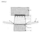
- Drawing 1 shows an embodiment in a side view, drawing 2, the same embodiment in a vertical side view.
- the laser-active solid (1) is in In this embodiment, an yttrium orthovanadate crystal associated with the laser active material Neodymium is doped.
- This laser-active solid (1) has dimensions of 12 mm x 1.5 mm x 0.3 mm. It is firmly connected to the non-laser-active solid (2), which is here considered a pure Yttrium orthovanadate crystal is performed without neodymium doping.
- This one in side view (Drawing 2) trapezoidal crystal has a footprint of 12 mm x 1.5 mm and a parallel top surface of 10.5 mm x 1.5 mm with a height of 8.5 mm.
- the laser-active solid (1) and the non-laser-active solid (2) fixed interconnecting is in the process of diffusion bonding.
- Both crystals are polished flat on the surfaces to be joined, pressed together, and heated to near its melting point. The crystals combine almost insoluble together.
- the process is described by Onyx Optics of Fremont, California, USA. offered commercially.
- Other methods are also suitable, for example suitable ones Adhesive method or fusion method for bonding a laser glass to a non-laser active glass.
- the laser-active solid (1) is made with a layer system (3) one or more layers provided around the laser beam to be generated or amplified (8) to reflect.
- the layer system (3) can, for example, on its the laser-active Solid (1) facing side have a dielectric layer of magnesium fluoride, which has a relatively low refractive index, so that the laser beam at the interface between the laser-active solid (1) and the magnesium fluoride layer at sufficient large incident angle (measured from the surface normal) undergoes total reflection.
- a heat sink (4) which serves to dissipate the heat loss from the laser-active solid (1).
- This Fixing can be done, for example, by pressing on the heat sink (4) with an interposed thin indium foil, or by a thermally conductive adhesive.
- the heat sink (4) may be made of copper, for example, and in turn of a thermoelectric cooling element to be cooled.
- the pumping light source (5) can be, for example, a semiconductor laser which emits at a wavelength of 808 nm or 880 nm. Usual are about 1 cm long versions with many single emitters known as high power diode laser bars are. In the case of the embodiment, a laser bar with a continuous wave output could be used of 30 watts are used.
- the non-laser-active solid (2) is suitably polished on all sides, so that he the pump light (7) by total reflection at his Side surfaces leads.
- the layer system (3) is expediently designed so that it Also for the pumping light (7) is highly reflective, so that the first passage is not in the laser-active solid (1) absorbed portion of the pump light (7) after reflection on the Layer system (3) makes a second passage through the laser-active solid (1).
- An essential advantage of the invention lies in the fact that the system concept is adapted both to the rectangular geometry of the semiconductor laser bars and to the round beam cross section of a diffraction-limited TEM 00 laser mode.
- the strongly elongated surface of the laser-active solid adapts to the long dimension commercially available semiconductor laser bars advantageous.
- the pump light of one or multiple semiconductor laser bars without additional beam shaping in the laser-active solid be coupled.
- the TEM 00 laser mode has the theoretically best possible beam quality.
- the cross-sectional area of the laser beam must be circular and as small as possible. Without further diaphragms, the laser beam with the largest possible cross-sectional area sets in a resonator during laser operation.
- the angle between the laser beam (8) and the layer system (3) can be achieved that this is a laser beam with a square cross-section. The calculation of this angle with the methods of trigonometry is simple in itself, but leads to a transcendental equation that can not be solved analytically but only numerically.
- a TEM 00 mode By inserting a circular aperture in the resonator whose diameter is approximately equal to the width b of the laser-active solid, and the choice of suitable radii of curvature and distances of the resonator, a TEM 00 mode can be forced, which almost completely fills the laser-active medium.
- the pump light absorbed in the laser-active solid is converted into laser light with high efficiency.
- One factor which determines this efficiency is the so-called fill factor, which is the area ratio of laser beam cross-sectional area to the free laser beam aperture of the laser-active solid.
- the large cooled surface of the laser-active solid in conjunction with its small thickness efficient cooling and thus a high output power allowed. It is particularly important that, unlike the disk laser, the cooled surface is much larger than the laser beam cross-sectional area, so that the high output power can be achieved at the same time good beam quality. This is inventively by the shallow angle of the laser beam (8) relative to the cooled surface, d. H. relative to the layer system (3) achieved.
- Another decisive advantage of the invention is that the laser beam also at high pumping power by the temperature gradients in the laser-active solid not negative being affected. This is because according to the invention a homogeneous heating of the laser-active Solid body achieved by the pump light in all planes parallel to the cooled surface becomes. If then the cooled surface is cooled evenly, then the crystal is formed Temperature field having isothermal planes parallel to the cooled surface. The laser beam passes through this temperature field at a shallow angle to the isothermal levels, d. H. at a large angle (greater than 45 °, typically about 60 ° to 89 °) relative to the temperature gradient, which is perpendicular to the isothermal levels.
- the laser beam is reflected on the highly reflective layer system and passes through the temperature field a second time before leaving the laser-active solid. If one grasps the laser beam as a bundle of parallel, thin partial beams, so passes through each partial beam - with less time delay - the same temperature differences.
- the optical path that i. a. by virtue of the temperature dependence of the refractive index is a function of temperature is therefore for all sub-beams on the way through the laser-active solid of the same length and it gives no influence of the temperature field on the phase surface of the laser beam.
- non-laser-active solid (2) there are no heat sources.
- This body is at all External surfaces thermally insulated by the surrounding air (or vacuum), except for the bonding surface with the laser-active solid (1).
- this interface is an isothermal plane, as explained in the last paragraph. Therefore, there are non-laser active solids no temperature gradients and therefore no thermal lensing and no thermo-optical aberrations.
- the parallel isothermal planes continue to lead to a nearly flat stress state in the laser-active solid and in the non-laser-active solid. Such a state of tension does not cause depolarization of the laser beam. This is a big advantage over Rod lasers.
- the first layer of the layer system on the laser-active solid as a layer with a relatively small refractive index, so that the laser beam at this Layer undergoes total reflection. In this way, no reflection losses for the laser beam, as with other laser concepts with large angles of incidence and multilayer systems the case is.
- Dielectric layers have i. A. a low specific thermal conductivity and the smaller the number and the Thickness of the layers of the layer system, the lower the total thermal resistance of the shift system. Low thermal resistance allows effective cooling and thus a high laser power.
- the non-laser-active solid (2) is in the embodiment advantageously with light Trapezoidal side surfaces designed so that the laser beam (8) both at the entrance also at the exit into or out of the non-laser-active solid whose surfaces pierces vertically. This does not create disturbing astigmatism as in the known Slab lasers.
- the areas (9) at which the laser beam enters or leaves the non-laser-active solid are preferably provided with an antireflection layer in order to avoid reflection losses of the laser beam. If YVO 4 is used as the material for the non-laser-active solid, even with a ⁇ / 4 single layer, a reflectance of well below 0.1% for the ordinary beam can be achieved.
- the area at which the pumping light (7) for the first time in the non-laser-active solid (2) occurs is expediently provided with an antireflection coating.
- the non-laser-active solid is designed so that the pump light on his walls is guided by total reflection.
- the well-known formulas for total reflection and refraction of light revealed that the total reflection regardless of the angle at which the Pumplicht emitted from the semiconductor laser is satisfied, as long as the refractive index of the non-laser-active Solid is greater than about 1.4.
Landscapes
- Physics & Mathematics (AREA)
- Electromagnetism (AREA)
- Engineering & Computer Science (AREA)
- Plasma & Fusion (AREA)
- Optics & Photonics (AREA)
- Lasers (AREA)
- Laser Surgery Devices (AREA)
- Led Devices (AREA)
Applications Claiming Priority (2)
| Application Number | Priority Date | Filing Date | Title |
|---|---|---|---|
| DE10204246 | 2002-02-02 | ||
| DE10204246A DE10204246B4 (de) | 2002-02-02 | 2002-02-02 | Festkörper-Laserverstärkersystem |
Publications (3)
| Publication Number | Publication Date |
|---|---|
| EP1333547A2 true EP1333547A2 (fr) | 2003-08-06 |
| EP1333547A3 EP1333547A3 (fr) | 2004-03-17 |
| EP1333547B1 EP1333547B1 (fr) | 2006-04-19 |
Family
ID=7713587
Family Applications (1)
| Application Number | Title | Priority Date | Filing Date |
|---|---|---|---|
| EP03001954A Expired - Lifetime EP1333547B1 (fr) | 2002-02-02 | 2003-01-30 | Amplificateur laser à l'état solide |
Country Status (4)
| Country | Link |
|---|---|
| US (1) | US6944196B2 (fr) |
| EP (1) | EP1333547B1 (fr) |
| AT (1) | ATE323958T1 (fr) |
| DE (2) | DE10204246B4 (fr) |
Cited By (1)
| Publication number | Priority date | Publication date | Assignee | Title |
|---|---|---|---|---|
| WO2004107514A3 (fr) * | 2003-05-30 | 2005-02-10 | High Q Laser Production Gmbh | Procede et dispositif pour pomper un laser |
Families Citing this family (11)
| Publication number | Priority date | Publication date | Assignee | Title |
|---|---|---|---|---|
| US7535633B2 (en) * | 2005-01-10 | 2009-05-19 | Kresimir Franjic | Laser amplifiers with high gain and small thermal aberrations |
| FR2884977B1 (fr) * | 2005-04-22 | 2007-07-13 | Cie Ind Des Lasers Cilas Sa | Systeme actif composite pour laser a solide |
| US9014228B1 (en) | 2010-07-08 | 2015-04-21 | Clemson University Research Foundation | Hydrothermal growth of heterogeneous single crystals for solid state laser applications |
| US9493887B1 (en) | 2010-07-08 | 2016-11-15 | Clemson University Research Foundation | Heterogeneous single vanadate based crystals for Q-switched lasers and microlasers and method for forming same |
| US9506166B1 (en) | 2010-07-08 | 2016-11-29 | Clemson University Research Foundation | Method for forming heterogeneous single garnet based crystals for passive Q-switched lasers and microlasers |
| US9711928B2 (en) | 2012-06-22 | 2017-07-18 | Clemson University Research Foundation | Single crystals with internal doping with laser ions prepared by a hydrothermal method |
| US9469915B2 (en) | 2012-06-22 | 2016-10-18 | Clemson University Research Foundation | Hydrothermal growth of heterogeneous single crystals exhibiting amplified spontaneous emission suppression |
| US10156025B2 (en) | 2015-05-04 | 2018-12-18 | University Of South Carolina | Monolithic heterogeneous single crystals with multiple regimes for solid state laser applications |
| US11114813B2 (en) * | 2015-11-25 | 2021-09-07 | Raytheon Company | Integrated pumplight homogenizer and signal injector for high-power laser system |
| US10297968B2 (en) | 2015-11-25 | 2019-05-21 | Raytheon Company | High-gain single planar waveguide (PWG) amplifier laser system |
| CN109586152B (zh) * | 2019-01-18 | 2024-03-12 | 东莞理工学院 | 用于高功率掠入射板条激光器光束质量改善的泵浦结构 |
Family Cites Families (25)
| Publication number | Priority date | Publication date | Assignee | Title |
|---|---|---|---|---|
| US3631362A (en) * | 1968-08-27 | 1971-12-28 | Gen Electric | Face-pumped, face-cooled laser device |
| US5115445A (en) * | 1988-02-02 | 1992-05-19 | Massachusetts Institute Of Technology | Microchip laser array |
| US4949346A (en) * | 1989-08-14 | 1990-08-14 | Allied-Signal Inc. | Conductively cooled, diode-pumped solid-state slab laser |
| US5091915A (en) * | 1989-12-25 | 1992-02-25 | Mitsubishi Denki K.K. | Semiconductor laser excited solid laser device |
| US5063566A (en) * | 1990-04-30 | 1991-11-05 | Amoco Corporation | Internally-doubled, composite-cavity microlaser |
| US5131002A (en) * | 1991-02-12 | 1992-07-14 | Massachusetts Institute Of Technology | External cavity semiconductor laser system |
| US5311528A (en) * | 1991-08-30 | 1994-05-10 | Hoya Corporation | Solid-state laser device capable of stably producing an output laser beam at high power |
| US5317585A (en) * | 1992-08-17 | 1994-05-31 | Hughes Aircraft Company | Laser reflecting cavity with ASE suppression and heat removal |
| US5305345A (en) * | 1992-09-25 | 1994-04-19 | The United States Of America As Represented By The United States Department Of Energy | Zigzag laser with reduced optical distortion |
| US5315612A (en) * | 1993-03-11 | 1994-05-24 | National Research Council Of Canada | High efficiency transversely pumped solid-state slab laser |
| DE59410441D1 (de) * | 1993-07-02 | 2006-10-26 | Deutsch Zentr Luft & Raumfahrt | Laserverstärkersystem |
| US5386427A (en) * | 1994-02-10 | 1995-01-31 | Massachusetts Institute Of Technology | Thermally controlled lenses for lasers |
| US5796766A (en) * | 1994-08-23 | 1998-08-18 | Laser Power Corporation | Optically transparent heat sink for longitudinally cooling an element in a laser |
| US6002695A (en) * | 1996-05-31 | 1999-12-14 | Dpss Lasers, Inc. | High efficiency high repetition rate, intra-cavity tripled diode pumped solid state laser |
| US6101201A (en) * | 1996-10-21 | 2000-08-08 | Melles Griot, Inc. | Solid state laser with longitudinal cooling |
| DE19722943A1 (de) * | 1997-05-31 | 1998-12-03 | Ulrich Prof Dr Wittrock | Nicht-planarer Ringlaser |
| US6167069A (en) * | 1998-05-01 | 2000-12-26 | The Regents Of The University Of California | Thermal lens elimination by gradient-reduced zone coupling of optical beams |
| US5991315A (en) * | 1998-09-03 | 1999-11-23 | Trw Inc. | Optically controllable cooled saturable absorber Q-switch slab |
| US6665328B1 (en) * | 1999-01-19 | 2003-12-16 | Spectra Physics, Inc. | Diode-pumped laser with funnel-coupled pump source |
| US6347109B1 (en) * | 1999-01-25 | 2002-02-12 | The Regents Of The University Of California | High average power scaleable thin-disk laser |
| US6763050B2 (en) * | 2000-03-16 | 2004-07-13 | The Regents Of The University Of California | Method for optical pumping of thin laser media at high average power |
| DE10038006A1 (de) * | 2000-08-04 | 2002-02-21 | Haas Laser Gmbh & Co Kg | Laserverstärkeranordnung |
| US6810060B2 (en) * | 2001-02-13 | 2004-10-26 | The Boeing Company | High-average power active mirror solid-state laser with multiple subapertures |
| US20020110166A1 (en) * | 2001-02-14 | 2002-08-15 | Filgas David M. | Method and system for cooling a laser gain medium |
| US6667999B2 (en) * | 2001-08-17 | 2003-12-23 | Textron Corporation | Cooling of high power laser systems |
-
2002
- 2002-02-02 DE DE10204246A patent/DE10204246B4/de not_active Expired - Fee Related
-
2003
- 2003-01-30 EP EP03001954A patent/EP1333547B1/fr not_active Expired - Lifetime
- 2003-01-30 DE DE50302994T patent/DE50302994D1/de not_active Expired - Lifetime
- 2003-01-30 AT AT03001954T patent/ATE323958T1/de not_active IP Right Cessation
- 2003-01-31 US US10/356,337 patent/US6944196B2/en not_active Expired - Fee Related
Cited By (1)
| Publication number | Priority date | Publication date | Assignee | Title |
|---|---|---|---|---|
| WO2004107514A3 (fr) * | 2003-05-30 | 2005-02-10 | High Q Laser Production Gmbh | Procede et dispositif pour pomper un laser |
Also Published As
| Publication number | Publication date |
|---|---|
| DE50302994D1 (de) | 2006-05-24 |
| EP1333547B1 (fr) | 2006-04-19 |
| US6944196B2 (en) | 2005-09-13 |
| DE10204246B4 (de) | 2012-12-06 |
| EP1333547A3 (fr) | 2004-03-17 |
| ATE323958T1 (de) | 2006-05-15 |
| US20040076211A1 (en) | 2004-04-22 |
| DE10204246A1 (de) | 2003-08-14 |
Similar Documents
| Publication | Publication Date | Title |
|---|---|---|
| DE60121511T2 (de) | Optischer Verstärker mit stabförmigen, von der Endseite gepumpten Verstärkungsmedium | |
| DE69014068T2 (de) | Laserdiodengepumpte, integrierende Laservorrichtung. | |
| DE69808057T2 (de) | Laserpumpkavitätvorrichtung mit monolithischem lichtkonzentrator | |
| DE3639580C2 (fr) | ||
| DE60302451T2 (de) | Pumpverfahren für laserresonator und lasersystem | |
| DE69804202T2 (de) | Laservorrichtung mit integralem Pumplicht-Konzentrator | |
| EP1333547B1 (fr) | Amplificateur laser à l'état solide | |
| DE10220378A1 (de) | Laserlichtquellenvorrichtung | |
| AT515789B1 (de) | Microchip-Laser | |
| AT515674B1 (de) | Festkörperlaser | |
| DE69617938T2 (de) | Diodengepumpter laser mit kristallen mit starker thermaler fokussierung | |
| DE4101403C2 (de) | Halbleiterlaser-gepumpter Festkörperlaser | |
| EP1188206A1 (fr) | Laser a solide | |
| EP0741924B1 (fr) | Laser solide pompe transversalement | |
| DE60212377T2 (de) | System und verfahren zum pumpen eines plattenlasers | |
| DE102006039074B4 (de) | Optische Anordnung zum Pumpen von Festkörperlasern | |
| WO2017194489A1 (fr) | Corps solide, système d'amplification laser et laser à corps solide | |
| DE4008225C2 (de) | Laserdiodengepumpter Festkörperlaser | |
| DE4304178C2 (de) | Aktives gefaltetes Resonatorsystem | |
| DE602004001127T2 (de) | Seite gepumpte faserlaser | |
| EP1629576B1 (fr) | Procede et dispositif pour pomper un laser | |
| EP1466392B1 (fr) | Dispositif et procede d'excitation optique de cristaux actifs au laser avec absorption fonction de la polarisation | |
| DE10393190T5 (de) | Dünner Scheibenlaser mit einer Pumpquelle mit großer numerischer Apertur | |
| DE4207824C2 (de) | Laserkristall für einen Festkörperlaser oder -verstärker | |
| DE19758366B4 (de) | Verfahren und Vorrichtung zum optischen Pumpen von Wellenleiterlasern oder -verstärkern durch von Laserdioden emittiertes Licht |
Legal Events
| Date | Code | Title | Description |
|---|---|---|---|
| PUAI | Public reference made under article 153(3) epc to a published international application that has entered the european phase |
Free format text: ORIGINAL CODE: 0009012 |
|
| AK | Designated contracting states |
Designated state(s): AT BE BG CH CY CZ DE DK EE ES FI FR GB GR HU IE IT LI LU MC NL PT SE SI SK TR |
|
| AX | Request for extension of the european patent |
Extension state: AL LT LV MK RO |
|
| PUAL | Search report despatched |
Free format text: ORIGINAL CODE: 0009013 |
|
| AK | Designated contracting states |
Kind code of ref document: A3 Designated state(s): AT BE BG CH CY CZ DE DK EE ES FI FR GB GR HU IE IT LI LU MC NL PT SE SI SK TR |
|
| AX | Request for extension of the european patent |
Extension state: AL LT LV MK RO |
|
| RIC1 | Information provided on ipc code assigned before grant |
Ipc: 7H 01S 3/0941 B Ipc: 7H 01S 3/09 B Ipc: 7H 01S 3/063 A |
|
| 17P | Request for examination filed |
Effective date: 20040916 |
|
| 17Q | First examination report despatched |
Effective date: 20041011 |
|
| AKX | Designation fees paid |
Designated state(s): AT BE BG CH CY CZ DE DK EE ES FI FR GB GR HU IE IT LI LU MC NL PT SE SI SK TR |
|
| GRAP | Despatch of communication of intention to grant a patent |
Free format text: ORIGINAL CODE: EPIDOSNIGR1 |
|
| RIC1 | Information provided on ipc code assigned before grant |
Ipc: 7H 01S 3/0941 B Ipc: 7H 01S 3/063 A |
|
| GRAS | Grant fee paid |
Free format text: ORIGINAL CODE: EPIDOSNIGR3 |
|
| GRAA | (expected) grant |
Free format text: ORIGINAL CODE: 0009210 |
|
| AK | Designated contracting states |
Kind code of ref document: B1 Designated state(s): AT BE BG CH CY CZ DE DK EE ES FI FR GB GR HU IE IT LI LU MC NL PT SE SI SK TR |
|
| PG25 | Lapsed in a contracting state [announced via postgrant information from national office to epo] |
Ref country code: SI Free format text: LAPSE BECAUSE OF FAILURE TO SUBMIT A TRANSLATION OF THE DESCRIPTION OR TO PAY THE FEE WITHIN THE PRESCRIBED TIME-LIMIT Effective date: 20060419 Ref country code: IE Free format text: LAPSE BECAUSE OF FAILURE TO SUBMIT A TRANSLATION OF THE DESCRIPTION OR TO PAY THE FEE WITHIN THE PRESCRIBED TIME-LIMIT Effective date: 20060419 Ref country code: FI Free format text: LAPSE BECAUSE OF FAILURE TO SUBMIT A TRANSLATION OF THE DESCRIPTION OR TO PAY THE FEE WITHIN THE PRESCRIBED TIME-LIMIT Effective date: 20060419 Ref country code: SK Free format text: LAPSE BECAUSE OF FAILURE TO SUBMIT A TRANSLATION OF THE DESCRIPTION OR TO PAY THE FEE WITHIN THE PRESCRIBED TIME-LIMIT Effective date: 20060419 Ref country code: CZ Free format text: LAPSE BECAUSE OF FAILURE TO SUBMIT A TRANSLATION OF THE DESCRIPTION OR TO PAY THE FEE WITHIN THE PRESCRIBED TIME-LIMIT Effective date: 20060419 Ref country code: NL Free format text: LAPSE BECAUSE OF FAILURE TO SUBMIT A TRANSLATION OF THE DESCRIPTION OR TO PAY THE FEE WITHIN THE PRESCRIBED TIME-LIMIT Effective date: 20060419 Ref country code: IT Free format text: LAPSE BECAUSE OF FAILURE TO SUBMIT A TRANSLATION OF THE DESCRIPTION OR TO PAY THE FEE WITHIN THE PRESCRIBED TIME-LIMIT;WARNING: LAPSES OF ITALIAN PATENTS WITH EFFECTIVE DATE BEFORE 2007 MAY HAVE OCCURRED AT ANY TIME BEFORE 2007. THE CORRECT EFFECTIVE DATE MAY BE DIFFERENT FROM THE ONE RECORDED. Effective date: 20060419 |
|
| REG | Reference to a national code |
Ref country code: GB Ref legal event code: FG4D Free format text: NOT ENGLISH |
|
| REF | Corresponds to: |
Ref document number: 50302994 Country of ref document: DE Date of ref document: 20060524 Kind code of ref document: P |
|
| REG | Reference to a national code |
Ref country code: IE Ref legal event code: FG4D Free format text: LANGUAGE OF EP DOCUMENT: GERMAN |
|
| GBT | Gb: translation of ep patent filed (gb section 77(6)(a)/1977) |
Effective date: 20060621 |
|
| PG25 | Lapsed in a contracting state [announced via postgrant information from national office to epo] |
Ref country code: SE Free format text: LAPSE BECAUSE OF FAILURE TO SUBMIT A TRANSLATION OF THE DESCRIPTION OR TO PAY THE FEE WITHIN THE PRESCRIBED TIME-LIMIT Effective date: 20060719 Ref country code: DK Free format text: LAPSE BECAUSE OF FAILURE TO SUBMIT A TRANSLATION OF THE DESCRIPTION OR TO PAY THE FEE WITHIN THE PRESCRIBED TIME-LIMIT Effective date: 20060719 |
|
| PG25 | Lapsed in a contracting state [announced via postgrant information from national office to epo] |
Ref country code: ES Free format text: LAPSE BECAUSE OF FAILURE TO SUBMIT A TRANSLATION OF THE DESCRIPTION OR TO PAY THE FEE WITHIN THE PRESCRIBED TIME-LIMIT Effective date: 20060730 |
|
| PG25 | Lapsed in a contracting state [announced via postgrant information from national office to epo] |
Ref country code: PT Free format text: LAPSE BECAUSE OF FAILURE TO SUBMIT A TRANSLATION OF THE DESCRIPTION OR TO PAY THE FEE WITHIN THE PRESCRIBED TIME-LIMIT Effective date: 20060919 |
|
| NLV1 | Nl: lapsed or annulled due to failure to fulfill the requirements of art. 29p and 29m of the patents act | ||
| REG | Reference to a national code |
Ref country code: IE Ref legal event code: FD4D |
|
| ET | Fr: translation filed | ||
| PG25 | Lapsed in a contracting state [announced via postgrant information from national office to epo] |
Ref country code: MC Free format text: LAPSE BECAUSE OF NON-PAYMENT OF DUE FEES Effective date: 20070131 Ref country code: LI Free format text: LAPSE BECAUSE OF NON-PAYMENT OF DUE FEES Effective date: 20070131 Ref country code: CH Free format text: LAPSE BECAUSE OF NON-PAYMENT OF DUE FEES Effective date: 20070131 |
|
| PLBE | No opposition filed within time limit |
Free format text: ORIGINAL CODE: 0009261 |
|
| STAA | Information on the status of an ep patent application or granted ep patent |
Free format text: STATUS: NO OPPOSITION FILED WITHIN TIME LIMIT |
|
| 26N | No opposition filed |
Effective date: 20070122 |
|
| REG | Reference to a national code |
Ref country code: CH Ref legal event code: PL |
|
| BERE | Be: lapsed |
Owner name: TESAT-SPACECOM G.M.B.H. & CO. KG Effective date: 20070131 |
|
| PG25 | Lapsed in a contracting state [announced via postgrant information from national office to epo] |
Ref country code: BE Free format text: LAPSE BECAUSE OF NON-PAYMENT OF DUE FEES Effective date: 20070131 |
|
| PG25 | Lapsed in a contracting state [announced via postgrant information from national office to epo] |
Ref country code: GR Free format text: LAPSE BECAUSE OF FAILURE TO SUBMIT A TRANSLATION OF THE DESCRIPTION OR TO PAY THE FEE WITHIN THE PRESCRIBED TIME-LIMIT Effective date: 20060720 |
|
| PG25 | Lapsed in a contracting state [announced via postgrant information from national office to epo] |
Ref country code: BG Free format text: LAPSE BECAUSE OF FAILURE TO SUBMIT A TRANSLATION OF THE DESCRIPTION OR TO PAY THE FEE WITHIN THE PRESCRIBED TIME-LIMIT Effective date: 20060719 Ref country code: AT Free format text: LAPSE BECAUSE OF NON-PAYMENT OF DUE FEES Effective date: 20070130 |
|
| PG25 | Lapsed in a contracting state [announced via postgrant information from national office to epo] |
Ref country code: EE Free format text: LAPSE BECAUSE OF FAILURE TO SUBMIT A TRANSLATION OF THE DESCRIPTION OR TO PAY THE FEE WITHIN THE PRESCRIBED TIME-LIMIT Effective date: 20060419 |
|
| PG25 | Lapsed in a contracting state [announced via postgrant information from national office to epo] |
Ref country code: CY Free format text: LAPSE BECAUSE OF FAILURE TO SUBMIT A TRANSLATION OF THE DESCRIPTION OR TO PAY THE FEE WITHIN THE PRESCRIBED TIME-LIMIT Effective date: 20060419 Ref country code: LU Free format text: LAPSE BECAUSE OF NON-PAYMENT OF DUE FEES Effective date: 20070130 |
|
| PG25 | Lapsed in a contracting state [announced via postgrant information from national office to epo] |
Ref country code: HU Free format text: LAPSE BECAUSE OF FAILURE TO SUBMIT A TRANSLATION OF THE DESCRIPTION OR TO PAY THE FEE WITHIN THE PRESCRIBED TIME-LIMIT Effective date: 20061020 Ref country code: TR Free format text: LAPSE BECAUSE OF FAILURE TO SUBMIT A TRANSLATION OF THE DESCRIPTION OR TO PAY THE FEE WITHIN THE PRESCRIBED TIME-LIMIT Effective date: 20060419 |
|
| REG | Reference to a national code |
Ref country code: DE Ref legal event code: R082 Ref document number: 50302994 Country of ref document: DE Representative=s name: BEATE AVENHAUS, DE |
|
| REG | Reference to a national code |
Ref country code: DE Ref legal event code: R082 Ref document number: 50302994 Country of ref document: DE |
|
| PGFP | Annual fee paid to national office [announced via postgrant information from national office to epo] |
Ref country code: FR Payment date: 20120206 Year of fee payment: 10 |
|
| PGFP | Annual fee paid to national office [announced via postgrant information from national office to epo] |
Ref country code: DE Payment date: 20120123 Year of fee payment: 10 |
|
| PGFP | Annual fee paid to national office [announced via postgrant information from national office to epo] |
Ref country code: GB Payment date: 20120120 Year of fee payment: 10 |
|
| GBPC | Gb: european patent ceased through non-payment of renewal fee |
Effective date: 20130130 |
|
| REG | Reference to a national code |
Ref country code: FR Ref legal event code: ST Effective date: 20130930 |
|
| PG25 | Lapsed in a contracting state [announced via postgrant information from national office to epo] |
Ref country code: DE Free format text: LAPSE BECAUSE OF NON-PAYMENT OF DUE FEES Effective date: 20130801 |
|
| REG | Reference to a national code |
Ref country code: DE Ref legal event code: R119 Ref document number: 50302994 Country of ref document: DE Effective date: 20130801 |
|
| PG25 | Lapsed in a contracting state [announced via postgrant information from national office to epo] |
Ref country code: FR Free format text: LAPSE BECAUSE OF NON-PAYMENT OF DUE FEES Effective date: 20130131 Ref country code: GB Free format text: LAPSE BECAUSE OF NON-PAYMENT OF DUE FEES Effective date: 20130130 |