EP1334674A2 - Meuble de cuisine, en particulier une armoire suspendue - Google Patents
Meuble de cuisine, en particulier une armoire suspendue Download PDFInfo
- Publication number
- EP1334674A2 EP1334674A2 EP03002926A EP03002926A EP1334674A2 EP 1334674 A2 EP1334674 A2 EP 1334674A2 EP 03002926 A EP03002926 A EP 03002926A EP 03002926 A EP03002926 A EP 03002926A EP 1334674 A2 EP1334674 A2 EP 1334674A2
- Authority
- EP
- European Patent Office
- Prior art keywords
- thrust
- weight
- wall
- drawer
- guide
- Prior art date
- Legal status (The legal status is an assumption and is not a legal conclusion. Google has not performed a legal analysis and makes no representation as to the accuracy of the status listed.)
- Granted
Links
Images



Classifications
-
- A—HUMAN NECESSITIES
- A47—FURNITURE; DOMESTIC ARTICLES OR APPLIANCES; COFFEE MILLS; SPICE MILLS; SUCTION CLEANERS IN GENERAL
- A47B—TABLES; DESKS; OFFICE FURNITURE; CABINETS; DRAWERS; GENERAL DETAILS OF FURNITURE
- A47B51/00—Cabinets with means for moving compartments up and down
Definitions
- the invention relates to a kitchen furniture, in particular a wall cabinet, the one in a kitchen unit as a single body with or without shelves can be equipped or can be locked with a door.
- Wall cabinets for kitchen units are known from the prior art, which is attached to the wall in the area above a work surface become. Shelfs can be embedded in the wall cupboards to keep dishes or the like on it. Because these wall cabinets the top line above a work surface are special the upper shelves are difficult to access, so that with such Wall cabinets storage space is given, but this space often used only rarely due to its difficult accessibility become. They also offer wall units with shelves often only a storage space for dishes, such as plates, Cups or the like, with an individual special use not considered as storage space, for example for spice containers comes because of the difficult accessibility.
- a vertical thrust is that cooperates with a holding device that the thrust holds in different positions.
- the integration of a vertical Drawers in a wall cabinet have significant advantages themselves, which can be seen in the fact that, for example, the vertical Storage space available in the drawer directly into the work area the kitchenette can be pulled down so that, for example Utensils for the kitchen are kept in the work area can be. This allows you to always have it ready to hand, as is desired for spices, for example. It is also conceivable for example in this vertical thrust holder for knives or Electrical appliances etc. to accommodate, so when pulling down of the vertical thrust the devices or allowances are immediately within reach Are close.
- the objects can be made accordingly stow away quickly and are protected from access, such as by children, well secured.
- an electrical connection in the drawer such as for example sockets or lighting, so that when moving out indirect lighting is switched on especially the floor area but also the work area of the Illuminated work surface.
- the thrust has guides that are connected to the side walls of the Corpus interact. This results in a vertical guidance Thrust, which prevents the thrust from tilting. In addition, with the guides interact to unlock and lock to an unwanted Prevent the drawer from moving.
- the holding device can a winding device arranged on a shaft, for example for a cable that winds up or unwinds the cable, to which the drawer is attached with its rear wall.
- the wave is hollow, with a torsion spring arranged therein which is firmly braced against the body. This results in a controlled, balanced vertical movement over the Cable that interacts with the holding device.
- the vertical Thrust thus remains in any position or position without it being too an automatic movement comes.
- the torsion spring is of this type designed to match the thrust counterweight, and a compensating holding device is created which is an unwanted Moving the vertical thrust prevented.
- Torsion spring formed from a spiral spring, which is mounted on a shaft is the free end protruding from the hollow shaft on the side wall of the body is set. This results in a fixed operative connection with the fixed part of the body wall against which one End of the torsion spring is supported on the shaft, the other free end of the torsion spring against the weight of the vertical Schubes works.
- an electrically operated tubular motor can be arranged in the shaft, which in particular opens up the possibility of, for example, vertical thrust to move electrically.
- vertical thrust for the electrification of the thrust can in the vertical drawer, for example, sockets for electrical appliances or lamps can be arranged.
- the holding device consists of a weight that is balanced by a cable pull with the vertical thrust communicates.
- a vertical thrust is characterized by the fact that it is very flat and inexpensive builds, whereby it can also be easily integrated into the single body leaves.
- the weight is plate-shaped, whereby it is guided behind the bottom of the vertical slide. The weight is increasing thus a narrow space so that the drawer as such is deep can be trained.
- the flat design of the weight takes thus little space behind the thrust in the single body as such on.
- both the weight in the open position of the thrust as well as the thrust itself in the retracted position together with a snap device acts.
- the end positions are secured, so that an unwanted The process of vertical thrust is prevented.
- the holding device can this be formed from a toggle joint that with a Gas spring interacts.
- the gas pressure spring holds the Thrust in the end positions, as well as in a middle position.
- a guide is provided for the vertical push, which is in particular Characterized by a on the side wall of the single body definable one-piece shaped guide rail profile in which both the thrust and the plate-shaped weight are guided.
- a guide rail profile which integrative thrust and plate-shaped weight, allows easy space-saving and effective management of the weight-boost system.
- This points Guide rail profile in the area of the frame wall of the drawer a guide segment which engages in the frame wall.
- the frame wall is a first on the guide rail profile molded on the rear area, especially for the edge area of the plate-shaped weight is maintained.
- a second front area is provided for the guide rail profile is in the an intermediate wall to cover the thrust in the body can be snapped into place.
- the receiving profile for the intermediate wall has a U-shaped Profiling on, the front leg of the "U's" shorter is designed as the rear, so a simple snap / press the partition is made possible.
- the guide segment for the Preferably pushed on a U-shaped shape, the rear Area for receiving the edge area of the weight groove-shaped is trained.
- the weight be made individually interconnected strip-shaped segments are formed, which are arranged on the cable pull to vary in their number.
- the vertical thrust is concerned according to its objects to be held by the variability the weight can be balanced. So the possibility exists, in particular to influence the weight in order to to be able to adjust as balanced a weight system as possible.
- a Another option is to use removable, externally accessible ones Provide weights on the thrust.
- the scissors mechanism on the one hand on the body, preferably on the rear wall of the body, and on the other the drawer rear wall is fixed by means of articulation points.
- the scissor legs are articulated accordingly.
- Includes the scissor mechanism preferably three scissor legs, each are hingedly connected to one another at the ends.
- the scissor legs the length of the species is such that it is retracted of the thrust an aligned position between the rear wall and occupy the back of the body.
- the individual scissor legs lie in the retracted state one above the other, so that this also does not affect the volume of the thrust.
- the invention has at least one scissor leg an elongated hole opening for adjusting a joint. This creates the possibility that the scissor mechanism can be set or designed for different batches.
- Figures 1 and 2 show a wall cabinet 1, which is not in one Kitchen unit shown in detail as a single body 2 equipped with shelves can be, the body 2 closed with a door 3 can be.
- the body 2 is preferably in a vertical thrust 5 is arranged in its rear region 4 cooperates with a holding device 6, which the thrust 5 in different Positions, as is particularly the case in FIGS. 1 and 2 is recognizable, holds.
- 1 shows one in particular retracted thrust 5
- FIG. 2 an extended thrust 5 shows in perspective.
- the thrust 5 has guides 7, which with the side walls 8 of the body 2 cooperate. This results in for the vertical slide 5 a tilt-free guide in the wall cabinet 1, so that the drawer can be easily retracted or extended 5 is guaranteed.
- the shaft 9 is, as from the sectional side view of FIG. 6 recognizable, hollow and includes a torsion spring 16, which is firmly braced against the body 2. As in the cut 6, the torsion spring 16 can be seen a spiral spring 17 which is mounted on two inner shafts, whose free end protrudes from the hollow shaft 9 and on the body rare wall 8 is set. It goes without saying that when the cable 11 is unwound from the holding device 6, the Coil spring 17 is tensioned and a holding effect is achieved prevents the thrust 5 from falling automatically.
- the hollow shaft 9 is rotatably mounted so that it with the torsion spring 16 or coil spring 17 cooperates.
- an electric tubular motor not shown can be arranged, the winding and unwinding of the cable 11th takes place.
- An additional cable can also be carried with the cable 11 be what the electrification in the thrust 5 allows.
- the screen 15 is designed as a clip-on partition, so that despite the built-in vertical drawer 5 the bar hanger of the body 2 accessible and thus remain adjustable.
- FIGS 7 to 11 show a further embodiment of the holding device 6.
- Holding device 6 for balancing the vertical thrust 5 from one Weight 18, which is connected to the thrust 5 via a cable 11 stands.
- the weight 18 is plate-shaped and guided behind the bottom 19 of the vertical slide 5.
- Snap device 20 or 21 cooperates.
- Snap device 20 when the vertical drawer 5 is extended is, the snap device 21 acts when the vertical drawer 5 is retracted.
- Figure 8 shows in the sectional side view how the weight 18 between the vertical thrust 5 and the rear wall 12 of the Single body 2 fits and is guided.
- a guide 23 is proposed for the vertical thrust 5, the is characterized in that the guide 23 from one to the side walls 8.1 or 8.2 of the single body 2 definable one-piece molded Guide rail profile 24, in which both the thrust 5th and the plate-shaped weight 18 are guided.
- the Guide 23 designed as a guide rail profile 24 is in particular shown in Figures 9 and 10, wherein in Figure 9 in the Top view can be seen how the guide rail profile 24 Vertical thrust 5 and the plate-shaped weight 18 picks up.
- the guide rail profile 24 has in the area of the frame wall 25 of the thrust 5 on a guide segment 26, which in the frame wall 25 takes hold.
- the guide segment 26 points for the thrust 5 preferably a U-shaped formation 27.
- the guide rail profile 24 is characterized in the invention Further indicate that over the extension of the frame wall 25 on the Guide rail profile 24 formed a second front region 29 in which an intermediate wall 30 can be seen in FIGS. 8 and 9, to cover the drawer 5 can be snapped into the body 2.
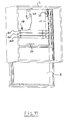
- FIG. 11 also shows a perspective view Single body 2, in which a vertical slide 5 is integrated.
- the special in the embodiment according to FIG. 11 is that the weight 18 from individual interconnected strip-shaped segments 18.1, 18.2 and 18.3 is formed on the cable 11 in their number are variably arranged. Now it goes without saying that an appropriate number can be docked on to this Balance thrust 5 and weight 18, this way the system can be balanced.
- For fine tuning can, for example, on the upper panel of the drawer 5 an additional Weight 34 to be placed.
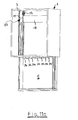
- Another way of FIG. 11a shows fine tuning, with the one accessible from the outside Weights 34 are arranged in the thrust 5.
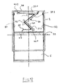
- FIG. 12 shows another embodiment of a top view Thrust 5.
- the thrust 5 indicates an electrification Electric cable 35 on; which is located behind the rear wall of the drawer. So that the electric cable 35 follows a controlled displacement path, a scissor mechanism 36 interacts with the electric cable 35.
- FIG. 12 the situation of a partially pulled out Thrust 5 shown. As can be seen from Figure 12, this is Electric cable 35 on the scissor legs 36 forming the scissors mechanism 37.1, 37.2 and 37.3 attached.
- the scissor mechanism 36 itself is on the one hand on the body 2, preferably on the rear wall of the body 38 and on the other hand on the thrust rear wall 39, by means of articulation points 40.1 and 40.2 attached. These joints 40.1 and 40.2 can be designed as a bearing body.
- Scissor mechanism 36 preferably comprises three scissor legs 37.1, 37.2 and 37.3, each of which is articulated to one another at the ends are.
- the scissor legs are 37.1, 37.2 and 37.3 the length of the species, see above that when the thrust 5 is retracted it is in alignment a superimposed position between the rear wall 39 with a Take socket 43 and the body rear wall 38. It points in particular the scissor legs 37.1 have a length that is the length of the scissor arm 37.2 covered, the scissor arm 37.2 again has a length that the scissor leg 37.3 in the retracted State of thrust 5 covered.
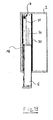
- FIG. 13 shows in a sectional side view how the scissor mechanism 36 fits into a vertical thrust 5, which with a Holding device 6 cooperates, which consists of a cable 11 guided weight 18 is composed.
- the scissors mechanism 36 lies then between the weight 18 and the intermediate wall 30, which is in the hanging body 2 is arranged to cover the thrust 5.
- FIG. 14 shows the interaction in positions a, b and c of the thrust 5 with a holding device 6, which consists of a toggle joint 44, which cooperates with a gas pressure spring 45.
- a holding device 6 which consists of a toggle joint 44, which cooperates with a gas pressure spring 45.
- the toggle mechanism of two rod-shaped elements 46 and 47, the free ends of which are connected on the one hand in a common hinge point 48, wherein on the other hand, one element 46 on the side wall of the body 2 is pivotally mounted, and the other element 47 on the thrust 5.
- At the common hinge point 48 engages the gas pressure spring 45 with one End, with the other end on the side wall of the body 2. is pivotally mounted.
- the two stage-shaped elements 46 and 47 have different positions, so that three positions, the Thrusts 5 are possible with this holding device 6.
Landscapes
- Drawers Of Furniture (AREA)
- Combinations Of Kitchen Furniture (AREA)
Applications Claiming Priority (6)
| Application Number | Priority Date | Filing Date | Title |
|---|---|---|---|
| DE20202037U | 2002-02-11 | ||
| DE20202037U DE20202037U1 (de) | 2002-02-11 | 2002-02-11 | Küchenmöbel, insbesondere Hängeschrank |
| DE20206484U | 2002-04-24 | ||
| DE20206484U DE20206484U1 (de) | 2002-04-24 | 2002-04-24 | Küchenmöbel insbesondere als Hängeschrank ausgebildeter Einzelkorpus |
| DE20206650U DE20206650U1 (de) | 2002-04-25 | 2002-04-25 | Schub für ein Möbel |
| DE20206650U | 2002-04-25 |
Publications (3)
| Publication Number | Publication Date |
|---|---|
| EP1334674A2 true EP1334674A2 (fr) | 2003-08-13 |
| EP1334674A3 EP1334674A3 (fr) | 2004-01-02 |
| EP1334674B1 EP1334674B1 (fr) | 2008-01-23 |
Family
ID=27617062
Family Applications (1)
| Application Number | Title | Priority Date | Filing Date |
|---|---|---|---|
| EP03002926A Expired - Lifetime EP1334674B1 (fr) | 2002-02-11 | 2003-02-10 | Meuble de cuisine, en particulier une armoire suspendue |
Country Status (3)
| Country | Link |
|---|---|
| EP (1) | EP1334674B1 (fr) |
| AT (1) | ATE384454T1 (fr) |
| DE (1) | DE50309052D1 (fr) |
Cited By (3)
| Publication number | Priority date | Publication date | Assignee | Title |
|---|---|---|---|---|
| WO2007131251A3 (fr) * | 2006-05-17 | 2008-10-30 | Blum Gmbh Julius | Meuble |
| EP2298128A3 (fr) * | 2009-08-22 | 2013-05-22 | Karl-Heinz Schuler | Dispositif d'extraction |
| CN115307713A (zh) * | 2022-07-01 | 2022-11-08 | 深圳市坤同智能仓储科技有限公司 | 一种称重组件线束调整方法、固定方法和称重设备 |
Family Cites Families (4)
| Publication number | Priority date | Publication date | Assignee | Title |
|---|---|---|---|---|
| BE669665A (fr) * | 1965-09-16 | 1965-12-31 | ||
| FR2382872A1 (fr) * | 1977-03-09 | 1978-10-06 | Dieste Pierre | Meuble haut escamotable de rangement |
| DE3914307A1 (de) * | 1989-04-29 | 1990-10-31 | Norbert Zimmermann | Haenge- oder oberschrank |
| US6250728B1 (en) * | 2000-01-21 | 2001-06-26 | Bobby J. Thorp | Hanging closet apparatus |
-
2003
- 2003-02-10 EP EP03002926A patent/EP1334674B1/fr not_active Expired - Lifetime
- 2003-02-10 DE DE50309052T patent/DE50309052D1/de not_active Expired - Lifetime
- 2003-02-10 AT AT03002926T patent/ATE384454T1/de active
Cited By (3)
| Publication number | Priority date | Publication date | Assignee | Title |
|---|---|---|---|---|
| WO2007131251A3 (fr) * | 2006-05-17 | 2008-10-30 | Blum Gmbh Julius | Meuble |
| EP2298128A3 (fr) * | 2009-08-22 | 2013-05-22 | Karl-Heinz Schuler | Dispositif d'extraction |
| CN115307713A (zh) * | 2022-07-01 | 2022-11-08 | 深圳市坤同智能仓储科技有限公司 | 一种称重组件线束调整方法、固定方法和称重设备 |
Also Published As
| Publication number | Publication date |
|---|---|
| EP1334674B1 (fr) | 2008-01-23 |
| EP1334674A3 (fr) | 2004-01-02 |
| ATE384454T1 (de) | 2008-02-15 |
| DE50309052D1 (de) | 2008-03-13 |
Similar Documents
| Publication | Publication Date | Title |
|---|---|---|
| EP3087866B1 (fr) | Armature pour une armoire angulaire et armoire angulaire dotée d'une armature | |
| DE60105253T2 (de) | Mehrzweckelement für in möbeln angeordnete gleitende metallfächer | |
| EP2424421A2 (fr) | Dispositif de réglage en hauteur d'un support guidé sur au moins une glissière d'extraction dans un appareil électroménager | |
| EP3558061B2 (fr) | Armoire | |
| DE29701227U1 (de) | Schrank mit verfahrbaren Fächern | |
| DE10101845C1 (de) | Schranklift | |
| EP3358258B1 (fr) | Meubles | |
| EP2241220B1 (fr) | Placard de hauteur d'étage | |
| EP1334674B1 (fr) | Meuble de cuisine, en particulier une armoire suspendue | |
| EP3804564B1 (fr) | Dispositif d'extraction pour armoire de coin | |
| EP1319352B1 (fr) | Un tiroir inférieur pour un meuble | |
| EP0314964B1 (fr) | Armoire suspendue en tôle | |
| EP3624637A1 (fr) | Mécanisme de levage, meuble ou appareil ménager et tiroir | |
| EP1264564B1 (fr) | Corps de meuble | |
| EP0035595A2 (fr) | Dispositif pour la fixation détachable d'un support extensible avec une monture | |
| DE20206484U1 (de) | Küchenmöbel insbesondere als Hängeschrank ausgebildeter Einzelkorpus | |
| DE2645481C3 (de) | Ständer für Gewürzbehälter o.dgl | |
| EP0807389A2 (fr) | Système de rangement pour ranger des objets | |
| DE19744819A1 (de) | Hängeschrank | |
| DE102004041861A1 (de) | Bodenseitiger Schubkasten | |
| AT527844A4 (de) | Aufsatzvorrichtung für eine Schublade | |
| DE20010930U1 (de) | Möbelkorpus | |
| DE20212951U1 (de) | Möbel mit Arbeitsplatte | |
| DE20202037U1 (de) | Küchenmöbel, insbesondere Hängeschrank | |
| DE202018105739U1 (de) | Vorratseinheit und Schrank |
Legal Events
| Date | Code | Title | Description |
|---|---|---|---|
| PUAI | Public reference made under article 153(3) epc to a published international application that has entered the european phase |
Free format text: ORIGINAL CODE: 0009012 |
|
| AK | Designated contracting states |
Designated state(s): AT BE BG CH CY CZ DE DK EE ES FI FR GB GR HU IE IT LI LU MC NL PT SE SI SK TR |
|
| AX | Request for extension of the european patent |
Extension state: AL LT LV MK RO |
|
| PUAL | Search report despatched |
Free format text: ORIGINAL CODE: 0009013 |
|
| AK | Designated contracting states |
Kind code of ref document: A3 Designated state(s): AT BE BG CH CY CZ DE DK EE ES FI FR GB GR HU IE IT LI LU MC NL PT SE SI SK TR |
|
| AX | Request for extension of the european patent |
Extension state: AL LT LV MK RO |
|
| 17P | Request for examination filed |
Effective date: 20040603 |
|
| AKX | Designation fees paid |
Designated state(s): AT BE BG CH CY CZ DE DK EE ES FI FR GB GR HU IE IT LI LU MC NL PT SE SI SK TR |
|
| 17Q | First examination report despatched |
Effective date: 20060620 |
|
| GRAP | Despatch of communication of intention to grant a patent |
Free format text: ORIGINAL CODE: EPIDOSNIGR1 |
|
| GRAS | Grant fee paid |
Free format text: ORIGINAL CODE: EPIDOSNIGR3 |
|
| GRAA | (expected) grant |
Free format text: ORIGINAL CODE: 0009210 |
|
| AK | Designated contracting states |
Kind code of ref document: B1 Designated state(s): AT BE BG CH CY CZ DE DK EE ES FI FR GB GR HU IE IT LI LU MC NL PT SE SI SK TR |
|
| REG | Reference to a national code |
Ref country code: GB Ref legal event code: FG4D Free format text: NOT ENGLISH |
|
| REG | Reference to a national code |
Ref country code: CH Ref legal event code: EP |
|
| REG | Reference to a national code |
Ref country code: IE Ref legal event code: FG4D Free format text: LANGUAGE OF EP DOCUMENT: GERMAN |
|
| REF | Corresponds to: |
Ref document number: 50309052 Country of ref document: DE Date of ref document: 20080313 Kind code of ref document: P |
|
| REG | Reference to a national code |
Ref country code: CH Ref legal event code: NV Representative=s name: BOVARD AG PATENTANWAELTE |
|
| NLV1 | Nl: lapsed or annulled due to failure to fulfill the requirements of art. 29p and 29m of the patents act | ||
| PG25 | Lapsed in a contracting state [announced via postgrant information from national office to epo] |
Ref country code: ES Free format text: LAPSE BECAUSE OF FAILURE TO SUBMIT A TRANSLATION OF THE DESCRIPTION OR TO PAY THE FEE WITHIN THE PRESCRIBED TIME-LIMIT Effective date: 20080504 Ref country code: FI Free format text: LAPSE BECAUSE OF FAILURE TO SUBMIT A TRANSLATION OF THE DESCRIPTION OR TO PAY THE FEE WITHIN THE PRESCRIBED TIME-LIMIT Effective date: 20080123 |
|
| GBV | Gb: ep patent (uk) treated as always having been void in accordance with gb section 77(7)/1977 [no translation filed] | ||
| PG25 | Lapsed in a contracting state [announced via postgrant information from national office to epo] |
Ref country code: BG Free format text: LAPSE BECAUSE OF FAILURE TO SUBMIT A TRANSLATION OF THE DESCRIPTION OR TO PAY THE FEE WITHIN THE PRESCRIBED TIME-LIMIT Effective date: 20080423 |
|
| BERE | Be: lapsed |
Owner name: ELCO KUNSTSTOFFE G.M.B.H. Effective date: 20080228 |
|
| PG25 | Lapsed in a contracting state [announced via postgrant information from national office to epo] |
Ref country code: PT Free format text: LAPSE BECAUSE OF FAILURE TO SUBMIT A TRANSLATION OF THE DESCRIPTION OR TO PAY THE FEE WITHIN THE PRESCRIBED TIME-LIMIT Effective date: 20080623 Ref country code: SI Free format text: LAPSE BECAUSE OF FAILURE TO SUBMIT A TRANSLATION OF THE DESCRIPTION OR TO PAY THE FEE WITHIN THE PRESCRIBED TIME-LIMIT Effective date: 20080123 |
|
| REG | Reference to a national code |
Ref country code: IE Ref legal event code: FD4D |
|
| PG25 | Lapsed in a contracting state [announced via postgrant information from national office to epo] |
Ref country code: MC Free format text: LAPSE BECAUSE OF NON-PAYMENT OF DUE FEES Effective date: 20080228 Ref country code: SK Free format text: LAPSE BECAUSE OF FAILURE TO SUBMIT A TRANSLATION OF THE DESCRIPTION OR TO PAY THE FEE WITHIN THE PRESCRIBED TIME-LIMIT Effective date: 20080123 Ref country code: SE Free format text: LAPSE BECAUSE OF FAILURE TO SUBMIT A TRANSLATION OF THE DESCRIPTION OR TO PAY THE FEE WITHIN THE PRESCRIBED TIME-LIMIT Effective date: 20080423 Ref country code: DK Free format text: LAPSE BECAUSE OF FAILURE TO SUBMIT A TRANSLATION OF THE DESCRIPTION OR TO PAY THE FEE WITHIN THE PRESCRIBED TIME-LIMIT Effective date: 20080123 Ref country code: NL Free format text: LAPSE BECAUSE OF FAILURE TO SUBMIT A TRANSLATION OF THE DESCRIPTION OR TO PAY THE FEE WITHIN THE PRESCRIBED TIME-LIMIT Effective date: 20080123 Ref country code: CZ Free format text: LAPSE BECAUSE OF FAILURE TO SUBMIT A TRANSLATION OF THE DESCRIPTION OR TO PAY THE FEE WITHIN THE PRESCRIBED TIME-LIMIT Effective date: 20080123 Ref country code: IE Free format text: LAPSE BECAUSE OF FAILURE TO SUBMIT A TRANSLATION OF THE DESCRIPTION OR TO PAY THE FEE WITHIN THE PRESCRIBED TIME-LIMIT Effective date: 20080123 |
|
| EN | Fr: translation not filed | ||
| PLBE | No opposition filed within time limit |
Free format text: ORIGINAL CODE: 0009261 |
|
| STAA | Information on the status of an ep patent application or granted ep patent |
Free format text: STATUS: NO OPPOSITION FILED WITHIN TIME LIMIT |
|
| 26N | No opposition filed |
Effective date: 20081024 |
|
| PG25 | Lapsed in a contracting state [announced via postgrant information from national office to epo] |
Ref country code: GB Free format text: LAPSE BECAUSE OF FAILURE TO SUBMIT A TRANSLATION OF THE DESCRIPTION OR TO PAY THE FEE WITHIN THE PRESCRIBED TIME-LIMIT Effective date: 20080123 |
|
| PG25 | Lapsed in a contracting state [announced via postgrant information from national office to epo] |
Ref country code: EE Free format text: LAPSE BECAUSE OF FAILURE TO SUBMIT A TRANSLATION OF THE DESCRIPTION OR TO PAY THE FEE WITHIN THE PRESCRIBED TIME-LIMIT Effective date: 20080123 |
|
| PG25 | Lapsed in a contracting state [announced via postgrant information from national office to epo] |
Ref country code: BE Free format text: LAPSE BECAUSE OF NON-PAYMENT OF DUE FEES Effective date: 20080228 |
|
| PG25 | Lapsed in a contracting state [announced via postgrant information from national office to epo] |
Ref country code: FR Free format text: LAPSE BECAUSE OF FAILURE TO SUBMIT A TRANSLATION OF THE DESCRIPTION OR TO PAY THE FEE WITHIN THE PRESCRIBED TIME-LIMIT Effective date: 20081114 |
|
| PG25 | Lapsed in a contracting state [announced via postgrant information from national office to epo] |
Ref country code: CY Free format text: LAPSE BECAUSE OF FAILURE TO SUBMIT A TRANSLATION OF THE DESCRIPTION OR TO PAY THE FEE WITHIN THE PRESCRIBED TIME-LIMIT Effective date: 20080123 |
|
| PG25 | Lapsed in a contracting state [announced via postgrant information from national office to epo] |
Ref country code: IT Free format text: LAPSE BECAUSE OF FAILURE TO SUBMIT A TRANSLATION OF THE DESCRIPTION OR TO PAY THE FEE WITHIN THE PRESCRIBED TIME-LIMIT Effective date: 20080123 |
|
| PG25 | Lapsed in a contracting state [announced via postgrant information from national office to epo] |
Ref country code: HU Free format text: LAPSE BECAUSE OF FAILURE TO SUBMIT A TRANSLATION OF THE DESCRIPTION OR TO PAY THE FEE WITHIN THE PRESCRIBED TIME-LIMIT Effective date: 20080724 Ref country code: LU Free format text: LAPSE BECAUSE OF NON-PAYMENT OF DUE FEES Effective date: 20080210 |
|
| PG25 | Lapsed in a contracting state [announced via postgrant information from national office to epo] |
Ref country code: TR Free format text: LAPSE BECAUSE OF FAILURE TO SUBMIT A TRANSLATION OF THE DESCRIPTION OR TO PAY THE FEE WITHIN THE PRESCRIBED TIME-LIMIT Effective date: 20080123 |
|
| PG25 | Lapsed in a contracting state [announced via postgrant information from national office to epo] |
Ref country code: GR Free format text: LAPSE BECAUSE OF FAILURE TO SUBMIT A TRANSLATION OF THE DESCRIPTION OR TO PAY THE FEE WITHIN THE PRESCRIBED TIME-LIMIT Effective date: 20080424 |
|
| REG | Reference to a national code |
Ref country code: CH Ref legal event code: PFA Owner name: ELCO KUNSTSTOFFE GMBH Free format text: ELCO KUNSTSTOFFE GMBH#OSNABRUECKER LANDSTRASSE 154#33335 GUETERSLOH (DE) -TRANSFER TO- ELCO KUNSTSTOFFE GMBH#OSNABRUECKER LANDSTRASSE 154#33335 GUETERSLOH (DE) |
|
| PGFP | Annual fee paid to national office [announced via postgrant information from national office to epo] |
Ref country code: DE Payment date: 20110318 Year of fee payment: 9 |
|
| PGFP | Annual fee paid to national office [announced via postgrant information from national office to epo] |
Ref country code: CH Payment date: 20110331 Year of fee payment: 9 |
|
| REG | Reference to a national code |
Ref country code: CH Ref legal event code: PUE Owner name: ELCO GMBH Free format text: ELCO KUNSTSTOFFE GMBH#OSNABRUECKER LANDSTRASSE 154#33335 GUETERSLOH (DE) -TRANSFER TO- ELCO GMBH#OSNABRUECKER LANDSTRASSE 154#33335 GUETERSLOH (DE) |
|
| REG | Reference to a national code |
Ref country code: DE Ref legal event code: R082 Ref document number: 50309052 Country of ref document: DE Representative=s name: PATENTANWAELTE MELDAU - STRAUSS - FLOETOTTO, DE |
|
| REG | Reference to a national code |
Ref country code: DE Ref legal event code: R082 Ref document number: 50309052 Country of ref document: DE Representative=s name: PATENTANWAELTE MELDAU - STRAUSS - FLOETOTTO, DE Effective date: 20111227 Ref country code: DE Ref legal event code: R081 Ref document number: 50309052 Country of ref document: DE Owner name: ELCO GMBH, DE Free format text: FORMER OWNER: ELCO KUNSTSTOFFE GMBH, 33335 GUETERSLOH, DE Effective date: 20111227 |
|
| REG | Reference to a national code |
Ref country code: CH Ref legal event code: PL |
|
| PG25 | Lapsed in a contracting state [announced via postgrant information from national office to epo] |
Ref country code: CH Free format text: LAPSE BECAUSE OF NON-PAYMENT OF DUE FEES Effective date: 20120229 Ref country code: LI Free format text: LAPSE BECAUSE OF NON-PAYMENT OF DUE FEES Effective date: 20120229 |
|
| REG | Reference to a national code |
Ref country code: AT Ref legal event code: PC Ref document number: 384454 Country of ref document: AT Kind code of ref document: T Owner name: ELCO GMBH, DE Effective date: 20120920 |
|
| REG | Reference to a national code |
Ref country code: DE Ref legal event code: R119 Ref document number: 50309052 Country of ref document: DE Effective date: 20120901 |
|
| PGFP | Annual fee paid to national office [announced via postgrant information from national office to epo] |
Ref country code: AT Payment date: 20120626 Year of fee payment: 10 |
|
| PG25 | Lapsed in a contracting state [announced via postgrant information from national office to epo] |
Ref country code: DE Free format text: LAPSE BECAUSE OF NON-PAYMENT OF DUE FEES Effective date: 20120901 |
|
| REG | Reference to a national code |
Ref country code: AT Ref legal event code: MM01 Ref document number: 384454 Country of ref document: AT Kind code of ref document: T Effective date: 20130228 |
|
| PG25 | Lapsed in a contracting state [announced via postgrant information from national office to epo] |
Ref country code: AT Free format text: LAPSE BECAUSE OF NON-PAYMENT OF DUE FEES Effective date: 20130228 |