EP1335094A2 - Einbau von architektonischen Dekorelementen in ein Bauwerk - Google Patents
Einbau von architektonischen Dekorelementen in ein Bauwerk Download PDFInfo
- Publication number
- EP1335094A2 EP1335094A2 EP03250445A EP03250445A EP1335094A2 EP 1335094 A2 EP1335094 A2 EP 1335094A2 EP 03250445 A EP03250445 A EP 03250445A EP 03250445 A EP03250445 A EP 03250445A EP 1335094 A2 EP1335094 A2 EP 1335094A2
- Authority
- EP
- European Patent Office
- Prior art keywords
- component
- locating
- building
- frame
- architectural finishing
- Prior art date
- Legal status (The legal status is an assumption and is not a legal conclusion. Google has not performed a legal analysis and makes no representation as to the accuracy of the status listed.)
- Withdrawn
Links
Images






Classifications
-
- E—FIXED CONSTRUCTIONS
- E04—BUILDING
- E04F—FINISHING WORK ON BUILDINGS, e.g. STAIRS, FLOORS
- E04F19/00—Other details of constructional parts for finishing work on buildings
- E04F19/005—Chimney mantel pieces
-
- E—FIXED CONSTRUCTIONS
- E04—BUILDING
- E04F—FINISHING WORK ON BUILDINGS, e.g. STAIRS, FLOORS
- E04F19/00—Other details of constructional parts for finishing work on buildings
- E04F19/02—Borders; Finishing strips, e.g. beadings; Light coves
- E04F19/04—Borders; Finishing strips, e.g. beadings; Light coves for use between floor or ceiling and wall, e.g. skirtings
- E04F19/0459—Borders; Finishing strips, e.g. beadings; Light coves for use between floor or ceiling and wall, e.g. skirtings characterised by the fixing method
- E04F19/0463—Plinths fixed by snap-action in a direction perpendicular to the wall
-
- E—FIXED CONSTRUCTIONS
- E04—BUILDING
- E04F—FINISHING WORK ON BUILDINGS, e.g. STAIRS, FLOORS
- E04F19/00—Other details of constructional parts for finishing work on buildings
- E04F19/02—Borders; Finishing strips, e.g. beadings; Light coves
- E04F19/04—Borders; Finishing strips, e.g. beadings; Light coves for use between floor or ceiling and wall, e.g. skirtings
- E04F19/049—Plinths specially adapted for joining wall coverings to floor surfaces
-
- E—FIXED CONSTRUCTIONS
- E04—BUILDING
- E04F—FINISHING WORK ON BUILDINGS, e.g. STAIRS, FLOORS
- E04F19/00—Other details of constructional parts for finishing work on buildings
- E04F19/02—Borders; Finishing strips, e.g. beadings; Light coves
- E04F19/04—Borders; Finishing strips, e.g. beadings; Light coves for use between floor or ceiling and wall, e.g. skirtings
- E04F19/0495—Plinths fixed around wall openings or around corners of walls
-
- E—FIXED CONSTRUCTIONS
- E06—DOORS, WINDOWS, SHUTTERS, OR ROLLER BLINDS IN GENERAL; LADDERS
- E06B—FIXED OR MOVABLE CLOSURES FOR OPENINGS IN BUILDINGS, VEHICLES, FENCES OR LIKE ENCLOSURES IN GENERAL, e.g. DOORS, WINDOWS, BLINDS, GATES
- E06B1/00—Border constructions of openings in walls, floors, or ceilings; Frames to be rigidly mounted in such openings
- E06B1/02—Base frames, i.e. template frames for openings in walls or the like, provided with means for securing a further rigidly-mounted frame; Special adaptations of frames to be fixed therein
-
- E—FIXED CONSTRUCTIONS
- E06—DOORS, WINDOWS, SHUTTERS, OR ROLLER BLINDS IN GENERAL; LADDERS
- E06B—FIXED OR MOVABLE CLOSURES FOR OPENINGS IN BUILDINGS, VEHICLES, FENCES OR LIKE ENCLOSURES IN GENERAL, e.g. DOORS, WINDOWS, BLINDS, GATES
- E06B1/00—Border constructions of openings in walls, floors, or ceilings; Frames to be rigidly mounted in such openings
- E06B1/04—Frames for doors, windows, or the like to be fixed in openings
- E06B1/06—Wooden frames
- E06B1/08—Wooden frames composed of several parts with respect to the cross-section of the frame itself
- E06B1/10—Wooden frames composed of several parts with respect to the cross-section of the frame itself adjustable with respect to the thickness of walls
-
- E—FIXED CONSTRUCTIONS
- E06—DOORS, WINDOWS, SHUTTERS, OR ROLLER BLINDS IN GENERAL; LADDERS
- E06B—FIXED OR MOVABLE CLOSURES FOR OPENINGS IN BUILDINGS, VEHICLES, FENCES OR LIKE ENCLOSURES IN GENERAL, e.g. DOORS, WINDOWS, BLINDS, GATES
- E06B1/00—Border constructions of openings in walls, floors, or ceilings; Frames to be rigidly mounted in such openings
- E06B1/04—Frames for doors, windows, or the like to be fixed in openings
- E06B1/34—Coverings, e.g. protecting against weather, for decorative purposes
-
- E—FIXED CONSTRUCTIONS
- E06—DOORS, WINDOWS, SHUTTERS, OR ROLLER BLINDS IN GENERAL; LADDERS
- E06B—FIXED OR MOVABLE CLOSURES FOR OPENINGS IN BUILDINGS, VEHICLES, FENCES OR LIKE ENCLOSURES IN GENERAL, e.g. DOORS, WINDOWS, BLINDS, GATES
- E06B1/00—Border constructions of openings in walls, floors, or ceilings; Frames to be rigidly mounted in such openings
- E06B1/56—Fastening frames to the border of openings or to similar contiguous frames
- E06B1/58—Fastening frames to the border of openings or to similar contiguous frames by filling up the joints, e.g. by cementing
-
- E—FIXED CONSTRUCTIONS
- E06—DOORS, WINDOWS, SHUTTERS, OR ROLLER BLINDS IN GENERAL; LADDERS
- E06B—FIXED OR MOVABLE CLOSURES FOR OPENINGS IN BUILDINGS, VEHICLES, FENCES OR LIKE ENCLOSURES IN GENERAL, e.g. DOORS, WINDOWS, BLINDS, GATES
- E06B1/00—Border constructions of openings in walls, floors, or ceilings; Frames to be rigidly mounted in such openings
- E06B1/56—Fastening frames to the border of openings or to similar contiguous frames
- E06B1/60—Fastening frames to the border of openings or to similar contiguous frames by mechanical means, e.g. anchoring means
- E06B1/6015—Anchoring means
-
- E—FIXED CONSTRUCTIONS
- E06—DOORS, WINDOWS, SHUTTERS, OR ROLLER BLINDS IN GENERAL; LADDERS
- E06B—FIXED OR MOVABLE CLOSURES FOR OPENINGS IN BUILDINGS, VEHICLES, FENCES OR LIKE ENCLOSURES IN GENERAL, e.g. DOORS, WINDOWS, BLINDS, GATES
- E06B1/00—Border constructions of openings in walls, floors, or ceilings; Frames to be rigidly mounted in such openings
- E06B1/56—Fastening frames to the border of openings or to similar contiguous frames
- E06B1/60—Fastening frames to the border of openings or to similar contiguous frames by mechanical means, e.g. anchoring means
- E06B1/6015—Anchoring means
- E06B1/6038—Anchoring means specially adapted for being embedded in the wall
-
- E—FIXED CONSTRUCTIONS
- E06—DOORS, WINDOWS, SHUTTERS, OR ROLLER BLINDS IN GENERAL; LADDERS
- E06B—FIXED OR MOVABLE CLOSURES FOR OPENINGS IN BUILDINGS, VEHICLES, FENCES OR LIKE ENCLOSURES IN GENERAL, e.g. DOORS, WINDOWS, BLINDS, GATES
- E06B1/00—Border constructions of openings in walls, floors, or ceilings; Frames to be rigidly mounted in such openings
- E06B1/04—Frames for doors, windows, or the like to be fixed in openings
- E06B1/045—Frames for doors, windows, or the like to be fixed in openings with separate wing abutment strips, e.g. adjustable; Door stops
Definitions
- the uprights and the lintel may form three components of a window frame.
- the attachment means can lock the tie component to the locating component.
- a gap is formed in each of the opposed sides of the plate.
- this gap is inwardly extending. More preferably the gap extends between the straight flange and the bent flange for receiving opposed flanges of the locating component that are preferably inwardly extending.
- bent flange is cut and stamped into the opposed sides of the plate.
- the tie component is in preferably as previously described.
- the locating component has a substantially constant cross section along its whole length.
- the present invention also provides a method of installing at least one architectural finishing component in a building comprising: a) installing a first locating component having a telescopically adjustable depth in an opening of a wall to form a locating reference for an architectural finishing component, the first locating component having had its depth adjusted to match substantially the thickness of the wall.
- both the first and the second locating components are adapted to receive at least one architectural finishing component. These may all be fitted in a final step.
- the first locating component defines at least part of a door frame.
- the door frame has a standard upright height and a standard lintel width.
- the depth of all three elements is preferably adjustable. Such a door frame can then be adjusted for depth to match the thickness of the wall to fit neatly within an existing wall opening, for example one from which an undesired door frame has been removed.
- the architectural finishing component may be an architrave or a door or both.
- the method may then comprise installing the standard size but adjustable depth door frame in the wall opening, hanging a standard door having a height and width suitable for fitting in the door frame to one of the upright sections of the standard door frame and possibly then fitting architrave around the door frame.
- the at least one architectural finishing component is attached to the first or second locating component using a press-fit connection, e.g. using double-ended pins such as those defined herein.
- a press-fit connection e.g. using double-ended pins such as those defined herein.
- the press-fit connection is preferably achieved using separate components such as double-ended pins that are installed into holes or slots in the building components, other forms of press-fit engagement may be used.
- the first portion has an engagement means for engaging the bracket with a bracket receiving means of a locating component for the architectural finishing component, such as a door frame for a door.
- a bracket receiving means of a locating component for the architectural finishing component such as a door frame for a door.
- the press-fit connection is a double-ended pin connection, the locating component having a slot therein for receiving a first end of the double-ended pin, the second end extending, in use, into the architectural finishing component.
- the slot extends vertically.
- the bracket comprises a first arm and a second arm extending perpendicular to the first arm, the slot being provided in the first arm.
- the second arm has a trapezium shaped section along its length.
- the second arm is adapted to be driven into a wall or a door frame.
- the wall or door frame may have a receiving means for the second arm, such as a trapezium or dovetail sectioned vent or groove.
- the receiving means is in a back surface of a door frame that is to be fitted onto or into the wall.
- the bracket is L shaped.
- the present invention also provides a door frame component comprising a first frame portion and a second frame portion that are telescopically adjustable relative to each other and a doorstop portion, the doorstop portion being fixable, in use, to first, substantially co-planar faces of the two door frame portions to bridge any gap therebetween.
- the depth of the doorframe assembly is telescopically adjustable.
- Architraves may be used to cover the ends of the door frame portions to hide the adhesive foam or mortar between the components of the door frame assembly and the wall.
- the architectural finishing component is at least one joinery item such as a door or an architrave.
- the first locating component is made at least partially of a finished wood, medium density fibreboard (MDF), glass reinforced plastic or a ceramic material, e.g. a plaster based material or a mortar based material, or another commonly used building material so that the appearance of the component is conventional in the finished building.
- MDF medium density fibreboard
- the remaining parts for example the telescoping member, may be made of metal or a strong, stiff, plastics material, for example.
- a standardised door i.e. a door of a standard height and width
- a standardised skirting board i.e. a skirting board of a standard length and height
- a further advantage of the present invention is that a house purchaser can easily change the architectural finishing components to match his or her tastes or as and when the architectural finishing components become shabby.
- the pins can be pulled out of the slots, or they can be snapped off. If snapped off, the ends left in the slots will easily push into the space behind the locating component, to fall away from the slots under gravity.
- the architectural finishing component in these various aspects of the invention preferably is a joinery item such as a door, a door liner, a window, a window liner, a trim, a skirting board, a cornice, a dado rail or an architrave.
- the architectural finishing component is made of wood, medium density fibreboard (MDF), glass reinforced plastic or a ceramic material, e.g. a plaster based material or a mortar based material, or another commonly used building material so that the appearance of the component is conventional in the finished building.
- the architectural finishing component has a surface finish, thereby requiring no decoration upon installation.
- the locating component of the present invention can be fitted using or in conjunction with traditional construction methods, e.g. using nails.
- Use of these locating components allows a large part of the architectural finishing components to be prepared off site. They can therefore match one another. They can also be supplied as a set, complete with matching handles, locks and hinges. They can also be installed or fitted right at the end of the building process. This will not only save construction time by skilled labourers and reduce the risk of damage to the architectural finishing components but will also allow, for example, painters to spray finish walls and ceilings. Spray finishing walls is faster than painting with a brush or a roller and usually gives a better finish.
- the components of the present invention can be fitted using or in conjunction with traditional construction methods, e.g. using nails, mortar and adhesive.
- traditional construction methods e.g. using nails, mortar and adhesive.
- the first locating component is fixed to the wall using a foam adhesive since this fills any gaps between the first locating component and the wall and gives a strong result.
- the locating components 1 are metal sections 10 that are built into the fabric of the building at an early stage of construction.
- the term "skeletal” is used to imply that an outer skin, such as architectural finishing components can be supported by it. Thus, they form frameworks for the assembly.
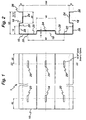
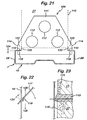
- the metal sections 10 shown in Figures 1, 2 and 21 are for making a door subframe 100 - see Figure 3.
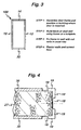
- the door sub-frame 100 is formed from two upright sections 12, and two horizontal sections 14, 16. These sections are of a predetermined size so that they fit together to form a fixed size, rectangular frame, the door sub-frame 100.
- the first horizontal section 14 may be designed to be capable of supporting a load as a lintel. Alternatively, a load-bearing lintel may need to be fitted for the doorway.
- the second horizontal section 16 is a floor section and may be a floorplate or it may be adapted to receive a floorplate thereon.
- the metal sections 10 of Figures 1, 2 and 21 comprise lengths of galvanised steel, preferably formed from a flat sheet of steel folded into the generally c-shaped section shown in Figure 2.
- the steel is galvanised for longevity, i.e. to prevent corrosion.
- the metal section 10 of Figure 1 has a number of slots 20, 24 provided along its length.
- the sheet may instead be made of rigid plastics materials or may be thicker and then may be made of wood or MDF.
- Two end sets of slots 20, 24 are shown in Figure 1. More slots are provided, equally spaced along the length of the metal section 10. Each slot is approximately 3mm wide and 12mm long. The slots at the ends of metal section 10 are provided with their centres about 25mm from the ends of the metal section 10. In total, 14 slots are provided along the length of the metal section 10. The length of the metal section 10, and the numbers of slots provided therealong, will, however, depend upon the application to which the metal section 10 is to be used. For the door sub-frame of Figure 3, the lengths may be about 2m for the uprights 12, and 1m for the horizontals 14, 16. The thickness of the metal section 10 is approximately 1mm.
- the metal section 10 is provided with three inward channels 18.
- the channels 18 are for receiving cables that may run along the length of the metal section 10 in the finished building.
- Each channel 18 has an approximate depth of 8mm.
- One channel 18 is provided in each side 28 of the c-shape and one channel 18 is provided at the middle of the back 29 of the c-shape.
- the channels 18 are not only for receiving cables, but also, once installed in a wall, provide spacing means to provide gaps 19 behind the metal sections 100, between the metal section 10 and the wall.
- the slots 20, 24 include a first set of slots 24 provided at intervals along the length of the section 10 at the midpoints of the channels 18.
- This first set of slots 24 is for allowing the metal section 10 to be fitted to a blockwall 27 in a traditional way, i.e. using cut nails 25.
- the slots may instead be holes.
- Glue may alternatively be used to fix the metal section 10 to the wall.
- a further alternative would be to use a tie to fix the metal section 10 to the wall, such as a butterfly tie similar to those used to tie an inner leave to an outer leave of a brickwork wall. Attachment means for the ties may be stamped into the section 10, for ecample. However, it is preferable for the door sub-frame 100 to be secured to the wall using cut nails 25 since this method has proved effective in prior art doorframes.
- a second set of slots 20 are also provided intermittently along the length of the metal section 10.
- the two sets of slots 20, 24 are located co-intermittently along the metal section 10.
- the second set of slots 20, however, are mounting points for attaching standard building components, i.e. the architectural finishing components (a door liner 22 and architrave 32), to the metal section 10 using pins 38, as shown in Figures 5, 6 and 9.
- the pins 38 extend through the slots 20 in the metal section 10 into the gaps 19 behind the metal section 10. If the pins 38 are ever snapped off, the ends of the pins 38 can fall down the gaps 19 under gravity so that they do not obscure the slots 20 in the event that replacement pins 38 are to be used in their place.
- the two sides 18 of the metal section 10 are arranged to be parallel to each other for providing a finished wall having parallel sides.
- the metal section 10 has edges 26. These edges 26 are co-planar with sides 28 of the metal section 10. These edges 26 provide a means for ensuring the skeletal building component can be built into the wall correctly, i.e. with plaster 30 applied to the walls to a level that is level with the edge 26. By doing this, a wall surface defined by the plaster 30, the edge 26, and the sidewalls 28 of the section 10 is flat. By making the wall surface flat, architrave 32 can be attached to the metal section 10 such that the back 34 of the architrave 32 lies against the plaster 30. Onto the back 29 of the metal section 10, a door liner 22 is attached. The door liner 22 has a width such that the architrave 32 has its back 34 resting also against edges 36 of the door liner 22, as shown in Figure 6.
- a double-ended pin 38 is used to join the door liner 22 and the architrave 32 to the metal section 10.
- One end of the pin 38 is driven or pushed into a pre-drilled or moulded hole (not shown) in the standard building component 22, 32.
- the other end locates into one of the slots 20 in the metal section 10. This ensures accurate assembly of standard building component 22, 32 to the skeletal building component, even when fitted by an unskilled labourer.
- the double-ended pin 38 is shown in detail in Figure 7.
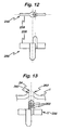
- the pin 38 comprises a first end 40, a second end 42 and a flange 44.
- Both ends 40, 42 are cylindrical fingers having points thereon for assisting in the insertion of the pin 38 into holes or slots in the building components.
- the two ends 40, 42 have different thicknesses to ensure that the pin is used in the correct orientation.
- the flange 44 is provided to ensure that the pin locates to a correct depth in both the slot 24 in the metal section 10 and the hole in the architectural finishing component. The flange 44 could, however, be omitted.
- the pin 38 is made of a plastics material or metal.
- Plastics materials have the advantage of being easier to sheer away from the metal section 10 by levering the architectural finishing component 22, 32 away from the metal section 10. This can therefore be done without damaging the metal section 10 or the architectural finishing component, thereby allowing the metal section 10 to be used for repetitive redecoration without the need for replacement or repair of the metal section 10.
- the architectural finishing component can also be reused if undamaged.
- the flange 144 comprises a base section 150 and an outer wall 152 defining a perimeter of an inverted cup.
- the shape of this cup 146 is oval to correspond with an elongated second pin 142.
- the outer wall is collapsible.
- a metal section 10 is fixed to the wall using one or more tie components 109. These can be similar to those used to tie an inner leave to an outer leave of a brickwork wall, i.e. butterfly ties. Attachment means (not shown) for such ties may, for example, be stamped into the section 10.
- the tie component 110 is slidably mountable to the locating component 1, as shown in Figures 21 to 23.
- the tie component 109 comprises a generally trapezium shaped sheet of metal (the plate 111) having apertures 112 extending therethrough.
- the apertures 112 allow mortar 113, in use, to lock the tie component 109 into the structural element 11 of the building (see Figure 23).
- each bent flange 116 is provided (see Figure 22).
- an L shaped cut is made in each side 114 of the plate.
- the feet 118 of each L shaped cut are made perpendicular to the sides 114.
- the legs 120 of each L shaped cut, perpendicular to the feet 118, are also cut into the plate. They extend parallel to the sides 114.
- These cuts complete the L shaped cuts of the tie component and form flanges.
- These flanges are then bent out of the plane of the plate along bend lines 122 that are also perpendicular to the sides 114 of the tie component 109. By bending the flanges out of plane, gaps 124 are formed in the sides of the tie component.
- two sides 28 of the metal section 10 of the locating component 1 are arranged to be parallel to each other for providing a finished wall having parallel sides.
- the sides 18, however, have inwardly facing opposed flanges 110.
- These inwardly facing opposed flanges 110 have a width suitable to fit snugly within the gaps 124 in the tie component, as can be seen in Figure 23, when the tie component is perpendicular to the locating component.
- the gaps allow the tie component to slide 126 relative to the locating component 1.
- the tie component 109 can be positioned at any point along the length of the locating component and, when re-oriented perpendicularly to the locating component 1, as shown in Figure 23, the bent flanges 116 engage against the flanges 110 of the locating component 1 to lock the tie component 109 in position relative to the locating component 1.
- This allows the tie component 109 to be positioned on top of a first building block 115, irrespective of the height of the block 115, or more specifically in the mortar between two building blocks 115.
- the metal section 200 further comprises a fourth planar wall 212 that is coplanar with the third planar wall 206.
- the lip 210 of this fourth wall 212 defines a height to which a floor screed 218 is applied so that the floor will end up flush with this lip 210.
- the planar walls 204, 206, 212 extend perpendicular to the floor screed 218.
- the metal section 200 is first of all fixed to a pre-built blockwall 216 using, for example, nails or glue.
- tie components 109 similar to those described in Figures 21 to 23 may be built into the wall, attached to the metal section 200 by stamping attached means into them (not shown).
- the metal section 200 is fixed either on or just above the floor. Then the wall 216 is plastered and painted down to the top of the third planar wall 206 and floor screed 218 is applied to the floor up to the lip 210 to provide a finished wall and a finished floor.
- a standardised skirting board 202 can then be attached to the metal section 200 with double-ended pins by an unskilled labourer. It will automatically be at the correct height relative to the floor, and level relative to the floor.
- the metal section 200 may be wide enough to rest directly on concrete floor slabs underneath the floor screed if required. Alternatively it may be positioned higher on the wall using a level.
- the wave shape of the metal section 200 defines a channel 222 for running cables (not shown) along the length of the metal section 200 between the metal section 200 and the skirting board 202.
- the skirting board 202 is provided with a recess 214 to increase the size of the channel 222.
- the wave shape also provides a gap 224, similar to that described above in relation to the door sub-frame 100, between the wall 216 and the metal section 200.
- the shape of the metal section 200 also allows plaster to be applied to the blockwall 216 with a flush finish against, or up to, the third planar wall 206. This allows the skirting board 202 to be attached to the metal section 200 such that its back wall 208 is flush with the plaster 30. This means that there will be no visible crack.
- a paired set of slots 20 are provided in the first two planar portions 204 for fixing the metal section 200 against the blockwall with nails (not shown).
- a third set of slots 24 is provided in the third planar wall 206 to allow the skirting board 202 to be fixed to the metal section 200 with double-ended pins, as previously described in relation to the first embodiment.
- the slots 20, 24 are intermittently spaced along the length of the metal section 200.
- skirting board sub-frame If installed using laser levelling techniques (which are standard practice when installing suspended ceilings and which could equally be used to get the skeletal building component level) a very accurate guide for the floor screed 218 is provided by the skirting board sub-frame, thereby ensuring that the floor is at the correct height for the door sets, and to ensure that the floor, skirting boards and other items are flat and level.
- locating components will be readily apparent to a skilled person, for example for affixing dado rails or picture rails to walls, perhaps using tie components attached to the locating components with clips and the like.
- a variant 244 of the double-ended fastener is shown. Again, a cup shaped flange is provided. However, two arcuate slots 245 are provided in the base of the cup to allow adhesive deposited in the cup to be absorbed by the architectural finishing component, which is preferably made of wood, MDF or some other absorbent building material. Round holes, vents or apertures, perhaps four equispaced holes, may alternatively be provided. These holes, vents, apertures or slots allow the adhesive to cure more quickly than would occur in a sealed cup. Additionally, the double-ended fastener 244 has an offset 246 for the axes of the two ends 248, 249.
- the doubled-ended fastener 244 can be used in situations where the slots 24 in the locating component 1 and the slots in the architectural finishing component are not precisely parallel to each other or aligned; by rotating the double-ended fastener 244 in one of the slots, an orientation for the fastener 244 can be found that enables the ends 248, 249 to align with the holes or the slots in both the locating component 1 and the architectural finishing component 22, 32, 202. For this to be effective, however, at least one of the components will need to have slots 24 for receiving the fasteners 244.
- a web 250 is provided extending diametrically across the centre of the cup 252. The web therefore extends effectively through both ends 248, 249 of the fastener.
- the web 250 can be used as a grip for the thumb and forefinger of the installer to enable the fastener 244 to be rotated more easily.
- a further variant of the fastener 256 is shown.
- a bar 258 is provided in place of the cup. This is easy to rotate and cheaper to manufacture.
- ramped steps 260 are provided on one of the ends of a double-ended fastener 256. Such ramped steps 260 could be provided on both of the ends.
- the ramped steps 260 form gripping serrations for the double-ended fastener 256 for engaging against the sides of the slots 24 in the locating component 1.
- the slots 24 are additionally provided with inwardly bent flanges 234 with points at the ends thereof for gripping the ramped steps to prevent removal of the end of the double-ended fastener from the slots once inserted into the slots.
- the ramped step might not be needed, however.
- the flanges may have knife edges that grip even smooth surfaced ends.
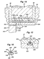
- FIG. 14 a cutaway sectional view of another architecturally finished building component in the form of a door frame 310 is shown.
- the section is through either one of the uprights of a door frame or a lintel of a door frame 310.
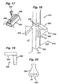
- the door frame 310 comprises two uprights 312 (one shown in Figure 18) and a lintel (not shown) perpendicular to and connecting the two uprights 312 towards the tops thereof.
- the bottoms 314 of the uprights 312 rest against the floor 218 (see Figure 18).
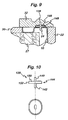
- the arrangement comprises a door 318, a doorstop or door slammer 320, two door liners 322, 324, two architraves 32, a slide bar 328 and two adjustment screws 330.
- the two door liners 322,324, are adhered to a wall 27 by a polyurethane foam adhesive 334.
- the wall 27 has plastered surfaces 30 on either side thereof against which the architraves 32 rest.
- the door liner 322 has a groove 338 cut in a wall facing side of it for receiving the slide bar 328. Part of the slide bar 328 is contained in the groove 338, with the remaining part of the slide bar 328 being located within the polyurethane foam adhesive 334. The screw 330 is also partially in the polyurethane foam adhesive 334. The remaining part of the screw 330 is screwed into the slide bar 328.
- the two door liners 322, 324 are generally long lengths. Generally they will have a length of approximately two metres. Along that length, a plurality of slide bars 328 may be provided. By way of example, it will be assumed that there are three slide bars 328.
- each slide bar 328 is a length of tubular steel.
- the length of the steel will typically be 10 cm.
- the slide bar has a generally regular, substantially trapezium shaped section.
- the section has a long base 340, two asymmetrical sides 342 and a slotted top 334.
- the slot 346 has inwardly depending flanges 348.
- the two flanges 348 generally oppose each other and are substantially parallel to each other.
- the asymmetrical sides 342 are able to flex resiliently to enable the slot 346 to widen upon screwing the screw 330 into the slot 346.
- the screw engages against the flanges 348.
- the screw is tapered to facilitate the expansion of the slot.
- the flanges may be tapered relative to each other, i.e. non parallel, such that the slot is narrower at its deepest point.
- screw receiving ports 350 are provided in the slot 346 for defining a position for the screw 330 to be inserted into the slot 346.
- Figure 17 only shows one such screw receiving port 350 since it only shows one end of the slide bar 328.
- a similar screw receiving port 350 would be provided at the other end of the slide bar 328 since two screws 330 are provided in the slide bar 328 as can clearly be seen in Figure 14. More screws can be used, however, if desired.
- the slide bar 328 is adapted to fit into the grooves 338 provided in each of the door liners 322, 324. Before the screws 330 are tightened into the slot 346 in the screw receiving ports 350, the slide bar 328 will freely slide within the groove 338. The fit can be a friction fit to prevent the door liners 322, 324 and the slide bars 328 (there are three of them, as described above) from falling apart too easily. However, they can be loosely fitting. Once the screws have been tightened in the slots 346, the asymmetric side walls 342 of the slide bar 328 will have been flexed outwardly to open the slot 346.
- one end of the slide bar 328 can be locked in position on one of the door liners 322, 324 before locking it in the groove 338 of the other door liner 322, 324. Then, once the depth of the two door liners 322, 324 has been adjusted to the required depth, i.e. the depth of the wall, the second screw 330 can be tightened to the lock the depth of the door liner.
- a door frame has been successfully fitted to the opening in the wall 27. It will have a standard size, in terms of height and width, to fit a standard sized door thereto.
- Figure 14 also shows a door slammer 320. This has been glued to the door frame, in particular to the two door liners, to bridge the gap 352 between the two door liners. It may alternatively be screwed or nailed to the door frame.
- the door frame is architecturally finished.
- the bracket 358 comprises a first arm 360 and a second arm 362.
- the two arms 360, 362 are arranged perpendicular to each other to form an L-shape.
- a slot 24 is provided at a distal end of the first arm 360.
- the length dimension of the slot is perpendicular to both of the axes of the arms.
- the second arm 362 has a trapezium shaped section of a size suitable to fit within the groove 338 of the door liner 322.
- the groove 338 could, however, have been cut into the uprights of a standard door frame.
- the slot 24 is for fixing architrave 32 to the wall 27 using, for example, double ended pin connections as described above.
- the first arm of the bracket 358 is also generally trapezium shaped. However, this is in plan, rather than in section. This is to provide a large distal end for receiving the slot 24. The other end is smaller to correspond with the size of the second arm section. This reduces the amount of material required to manufacture the brackets.
- the slot 24 is arranged substantially parallel to the top and bottom of the trapezium shaped second arm 362 and also the top and bottom of the trapezium shape of the first arm 60.
- a cut out 366 may be provided in the wall 27 for receiving the first arm 60 of the bracket 358.
- This cut out 364 need not be cut into the wall 27 accurately since it will eventually be covered by the architrave 32. However, it will generally correspond in depth to the thickness of the plaster 30. The cut out 364 will facilitate, however, the mounting of the architrave 32 flat against the wall 27. Alternatively, a suitable cut out could be provided in the architrave 32.
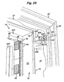
- FIG. 24 to 28 there is shown a further embodiment of the present invention.
- a door frame comprising two uprights 12 and a lintel 14 are shown fitted within a vent in a wall 27.
- the wall 27 has plaster 30 already applied thereto.
- brackets 358 have two arms 360, 362. See Figure 25.
- the second arm forms a dovetail for fitting in a dovetail groove (not shown) provided in the backs of the uprights 12. Similar grooves may also be provided in the lintel 14 for receiving further brackets (not shown).
- the bracket is made from a stiff material, preferably a plastics material and may be moulded.
- the two arms are substantially C-shaped in section to reduce the amount of material required in the moulding.
- the first arm 360 has a hollow back 48, a resilient flange 50 therein, and a solid nose 52.
- the solid nose has a bore 54 therein for receiving a nail 56. Alternatively, a screw may be used.
- the first arm 360 of the bracket 358 fits in a cutout 366 in the plaster 30 of the wall 27. This cut out will usually reveal the wooden surround 68 of a vent 58 for a door.
- a nail 56 can firmly attach the bracket 358 to this wooden surround 68.
- the wooden surround 68 in modern buildings is usually made from a 2-by-4 plank (dimensions of approximately 5cm by 10 cm or 2 inches by 4 inches). The nail 56 (or screw) can simply be driven through the bore 54 into the wooden surround 68 to secure the bracket 358 to the wall 27.
- This gap defines a slot 24 for a double ended fastener, as previously described, for attaching architrave 32 to the door frame. Because the flange extends resiliently from the base of the hollow back 48 of the bracket 358, the double ended pins can be securely retained in the slot 24, but yet removed relatively easily.
- the two opposed walls of the flange 50 and the nose 52 may be provided with gripping means (not shown) such as a rib or ribs.
- the flange 50 can be seen to have a radiused base 66. This prevents the flange 50 from snapping off the bracket as it is flexed by the insertion of the double ended fastener into the slot 24.
- the section of the dovetail of the second arm 362 can be seen also to be hollow 62 to give it its C-shaped section. This further reduces the amount of material required to make the brackets 358. It also allows the sides of the dovetail to flex, thereby easing the insertion of the dovetail into the grooves in the back of the uprights (and possibly also the lintel) of the door frame.
- the sides 64 of the dovetail may be provided with gripping means, such as ribs or serrations (not shown), to secure the dovetails in the grooves (not shown) provided in the backs of the uprights 12 (and lintel) more securely.
- gripping means such as ribs or serrations (not shown)
- the brackets will be glued into the grooves.
- the upright 12 is screwed (not shown) to the lintel at a right angle.
- the two pieces are provided with ends that have locating means to ensure that they are joined together correctly, and accurately.
- a groove 70 is provided at the top of the uprights 12 (one shown in detail).
- the groove is on the door facing surface 72 of each upright 12.
- the groove is perpendicular to the sides 74 of the upright and has a width corresponding to the thickness T L of the lintel 14 (see Figure 27).
- the groove 70 ensures that the lintel and the uprights fit together accurately with respect to the x and y axes as marked on Figure 27.
- More grooves 76 are provided in both the lintel 14 and the uprights 12, parallel to the sides of the lintel 14 and the uprights 12. These grooves 76 match each other, i.e. they are of the same size as each other and are spaced equally from the sides of the respective lintel 14 or uprights 12. They are for receiving door stops 320, which are also known as door slammers. In the base of these grooves 76 two strips of double sided adhesive tape 80 are provided, which may be foam backed, or substituted with some other adhesive. The tapes 80 are for gluing the door stops 320 into the grooves 76. Alternatively the door stops 320 may be nailed or screwed into the grooves 76.
- the door stops, the lintel and the uprights are preferably supplied in their finished condition, i.e. with all visible parts thereof, in the assembled door frame, painted or otherwise decorated.
- the groove 76 in the upright also serves another purpose.
- the door stop 320 in the groove 76 of the lintel extends for the full length of the lintel 14 into the groove 76 of the upright 12. Therefore, the combination of the groove 76 in the upright 12 and the door stop 320 in the groove 76 of the lintel 14 provides a locating means in the z axis of Figure 26, i.e. in and out of the page of Figure 27.
- the two grooves provide x, y and z axis locating means.
- Screw holes may also be predrilled into the lintel 14 and the uprights 12, and the parts supplied separately, for assisting in the assembly of the three components by the user.
- the door stops 320, lintel 14 and uprights are preferably made of a fibrous material, such as wood or MDF.
- grooves 82 are provided down the sides of the lintel and the uprights (see Figure 26). These grooves 82 receive the feet 84 of the architrave 32. The architrave, when fitted against the plaster 30 of the wall 27, will provide finished sides to the door frame. However, because of the side grooves 82, this can be achieved for a variety of widths of wall 27. The grooves 82 will provide a useful adjustment A of about 6mm for each side of the door frame, thereby giving a total variance capability of up to 12mm for the width of the door frame.
- the spacers 46 are made of a sticky backed, high density (i.e. low compressibility) foam pad.
- the adhesive is sufficiently untacky to be peelable from the door frame without leaving permanent marks on the surface finish of the door frame.
Landscapes
- Engineering & Computer Science (AREA)
- Architecture (AREA)
- Civil Engineering (AREA)
- Structural Engineering (AREA)
- Mechanical Engineering (AREA)
- Life Sciences & Earth Sciences (AREA)
- Wood Science & Technology (AREA)
- Door And Window Frames Mounted To Openings (AREA)
Priority Applications (1)
| Application Number | Priority Date | Filing Date | Title |
|---|---|---|---|
| EP06076774A EP1818494A3 (de) | 2002-02-11 | 2003-01-24 | Einbau von architektonischen Dekorelementen in ein Bauwerk |
Applications Claiming Priority (8)
| Application Number | Priority Date | Filing Date | Title |
|---|---|---|---|
| GB0203179A GB2385069A (en) | 2002-02-11 | 2002-02-11 | Installing architectural finishing components |
| GB0203179 | 2002-02-11 | ||
| GB0221816 | 2002-09-19 | ||
| GB0221814 | 2002-09-19 | ||
| GB0221816A GB2385103B (en) | 2002-02-11 | 2002-09-19 | Double-ended fastener for installing architectural finishing components in a building |
| GB0221814A GB2385083A (en) | 2002-02-11 | 2002-09-19 | Tie component for installing architectural components |
| GB0224895A GB2385085B (en) | 2002-02-11 | 2002-10-25 | Installing architectural finishing components in a building |
| GB0224895 | 2002-10-25 |
Related Child Applications (1)
| Application Number | Title | Priority Date | Filing Date |
|---|---|---|---|
| EP06076774A Division EP1818494A3 (de) | 2002-02-11 | 2003-01-24 | Einbau von architektonischen Dekorelementen in ein Bauwerk |
Publications (2)
| Publication Number | Publication Date |
|---|---|
| EP1335094A2 true EP1335094A2 (de) | 2003-08-13 |
| EP1335094A3 EP1335094A3 (de) | 2005-02-09 |
Family
ID=27617662
Family Applications (1)
| Application Number | Title | Priority Date | Filing Date |
|---|---|---|---|
| EP03250445A Withdrawn EP1335094A3 (de) | 2002-02-11 | 2003-01-24 | Einbau von architektonischen Dekorelementen in ein Bauwerk |
Country Status (1)
| Country | Link |
|---|---|
| EP (1) | EP1335094A3 (de) |
Cited By (7)
| Publication number | Priority date | Publication date | Assignee | Title |
|---|---|---|---|---|
| GB2433088A (en) * | 2005-12-09 | 2007-06-13 | Ian Douglas Law | Dovetail bar and bracket for depth adjustable frame assembly |
| FR2921091A1 (fr) * | 2007-09-18 | 2009-03-20 | Armor Iso Portes Sarl | Module comprenant une huisserie de porte et une imposte |
| CN102889041A (zh) * | 2011-11-18 | 2013-01-23 | 中国建筑第四工程局有限公司 | 外门窗防渗防热桥施工方法 |
| GB2503913A (en) * | 2012-07-11 | 2014-01-15 | Ultimate Doorlinings Ltd | Adjustable door frame lining |
| CN103527034A (zh) * | 2013-10-30 | 2014-01-22 | 无锡市安捷脚手架有限公司 | 带有复合层的铝型材 |
| EP2886771A1 (de) * | 2013-12-23 | 2015-06-24 | Eclisse Srl | Zentrierelement, insbesondere für vordere Pfosten für Wandeinbaurahmen zurückziehbarer Schiebetüren |
| WO2018197936A1 (en) * | 2017-04-27 | 2018-11-01 | Patel Vinod Khetabhai | A method for fitting a door frame in a wall recess |
Citations (4)
| Publication number | Priority date | Publication date | Assignee | Title |
|---|---|---|---|---|
| GB203179A (en) | 1922-08-28 | 1923-09-06 | Norman Howard Caufield | Improvements in stookers |
| GB221814A (en) | 1923-09-11 | 1924-12-18 | Otto Sindl | An improved drum for centrifuging apparatus |
| GB221816A (en) | 1923-09-12 | 1925-01-22 | Edmond Pasquet | Improvements relating to electric switches |
| GB224895A (en) | 1923-11-12 | 1925-09-03 | Marius Gjersoe | Improvements in electric furnaces |
Family Cites Families (5)
| Publication number | Priority date | Publication date | Assignee | Title |
|---|---|---|---|---|
| DE818845C (de) * | 1948-12-24 | 1951-10-29 | Remi Dirckx | Verbindungsvorrichtung fuer Umrahmungen von Tueren, Fenstern und Holzbauteilen aller Art |
| CH484353A (de) * | 1967-03-31 | 1970-01-15 | Pelz Ernst | Türrahmen |
| NL7400719A (en) * | 1974-01-18 | 1975-07-22 | Barsema S Timmerfabriek B V | Wooden window or door assembly - has intermediate frame of ribbed slats fitting in grooved outer one |
| SE461344B (sv) * | 1988-11-18 | 1990-02-05 | Swedoor Ab | Karm vid vaeggoeppning, av den typ daer en av karmstyckenas aendar aer foersaenkt foer upptagande av den andra karmstyckesaenden |
| US5974745A (en) * | 1996-04-25 | 1999-11-02 | Barr; Gerald L. | Self-aligning prefabricated door frame assembly |
-
2003
- 2003-01-24 EP EP03250445A patent/EP1335094A3/de not_active Withdrawn
Patent Citations (4)
| Publication number | Priority date | Publication date | Assignee | Title |
|---|---|---|---|---|
| GB203179A (en) | 1922-08-28 | 1923-09-06 | Norman Howard Caufield | Improvements in stookers |
| GB221814A (en) | 1923-09-11 | 1924-12-18 | Otto Sindl | An improved drum for centrifuging apparatus |
| GB221816A (en) | 1923-09-12 | 1925-01-22 | Edmond Pasquet | Improvements relating to electric switches |
| GB224895A (en) | 1923-11-12 | 1925-09-03 | Marius Gjersoe | Improvements in electric furnaces |
Cited By (8)
| Publication number | Priority date | Publication date | Assignee | Title |
|---|---|---|---|---|
| GB2433088A (en) * | 2005-12-09 | 2007-06-13 | Ian Douglas Law | Dovetail bar and bracket for depth adjustable frame assembly |
| FR2921091A1 (fr) * | 2007-09-18 | 2009-03-20 | Armor Iso Portes Sarl | Module comprenant une huisserie de porte et une imposte |
| CN102889041A (zh) * | 2011-11-18 | 2013-01-23 | 中国建筑第四工程局有限公司 | 外门窗防渗防热桥施工方法 |
| GB2503913A (en) * | 2012-07-11 | 2014-01-15 | Ultimate Doorlinings Ltd | Adjustable door frame lining |
| CN103527034A (zh) * | 2013-10-30 | 2014-01-22 | 无锡市安捷脚手架有限公司 | 带有复合层的铝型材 |
| CN103527034B (zh) * | 2013-10-30 | 2015-08-05 | 无锡市安捷脚手架有限公司 | 带有复合层的铝型材 |
| EP2886771A1 (de) * | 2013-12-23 | 2015-06-24 | Eclisse Srl | Zentrierelement, insbesondere für vordere Pfosten für Wandeinbaurahmen zurückziehbarer Schiebetüren |
| WO2018197936A1 (en) * | 2017-04-27 | 2018-11-01 | Patel Vinod Khetabhai | A method for fitting a door frame in a wall recess |
Also Published As
| Publication number | Publication date |
|---|---|
| EP1335094A3 (de) | 2005-02-09 |
Similar Documents
| Publication | Publication Date | Title |
|---|---|---|
| US5179811A (en) | Decorative trimming system | |
| US6385927B2 (en) | Decorative trim assemblies | |
| US6148883A (en) | Wood trim system | |
| US7228663B2 (en) | Decorative trim assemblies | |
| EP0842338B1 (de) | Modulares profilleistensystem | |
| US6276101B1 (en) | Door and window surround | |
| US6588159B1 (en) | Multipurpose door and window jamb assembly | |
| WO1997028342A1 (en) | Trim attachment system | |
| US4509294A (en) | Door frame assembly | |
| WO2001020101A1 (en) | Edgings | |
| US6463707B1 (en) | Decorative trim assemblies | |
| CA1285797C (en) | Fastening means | |
| EP0656984B1 (de) | Holzleiste | |
| EP1335094A2 (de) | Einbau von architektonischen Dekorelementen in ein Bauwerk | |
| US20230021420A1 (en) | Wall paneling system | |
| EP1818494A2 (de) | Einbau von architektonischen Dekorelementen in ein Bauwerk | |
| JPH0452367A (ja) | タイル、壁材の張付け工法 | |
| GB2404931A (en) | Locating and architectural component and method of installing in a building | |
| CA2244865C (en) | Trim attachment system | |
| CA1337096C (en) | Drywall construction | |
| US20060042178A1 (en) | Garden window sub frame assemblies | |
| AU687869B2 (en) | Reveal for window or door assembly | |
| GB2212829A (en) | Decorative cladding sheet and rail for walls | |
| AU712332B2 (en) | Reveal for window or door assembly | |
| CA2937208C (en) | Installation bracket for use with pre-hung interior and exterior doors, and windows |
Legal Events
| Date | Code | Title | Description |
|---|---|---|---|
| PUAI | Public reference made under article 153(3) epc to a published international application that has entered the european phase |
Free format text: ORIGINAL CODE: 0009012 |
|
| AK | Designated contracting states |
Designated state(s): AT BE BG CH CY CZ DE DK EE ES FI FR GB GR HU IE IT LI LU MC NL PT SE SI SK TR |
|
| AX | Request for extension of the european patent |
Extension state: AL LT LV MK RO |
|
| PUAL | Search report despatched |
Free format text: ORIGINAL CODE: 0009013 |
|
| AK | Designated contracting states |
Kind code of ref document: A3 Designated state(s): AT BE BG CH CY CZ DE DK EE ES FI FR GB GR HU IE IT LI LU MC NL PT SE SI SK TR |
|
| AX | Request for extension of the european patent |
Extension state: AL LT LV MK RO |
|
| 17P | Request for examination filed |
Effective date: 20050722 |
|
| AKX | Designation fees paid |
Designated state(s): AT BE BG CH CY CZ DE DK EE ES FI FR GB GR HU IE IT LI LU MC NL PT SE SI SK TR |
|
| STAA | Information on the status of an ep patent application or granted ep patent |
Free format text: STATUS: THE APPLICATION IS DEEMED TO BE WITHDRAWN |
|
| 18D | Application deemed to be withdrawn |
Effective date: 20060926 |