EP1335155A2 - Dispositif de transmission automatique de véhicule - Google Patents
Dispositif de transmission automatique de véhicule Download PDFInfo
- Publication number
- EP1335155A2 EP1335155A2 EP03001626A EP03001626A EP1335155A2 EP 1335155 A2 EP1335155 A2 EP 1335155A2 EP 03001626 A EP03001626 A EP 03001626A EP 03001626 A EP03001626 A EP 03001626A EP 1335155 A2 EP1335155 A2 EP 1335155A2
- Authority
- EP
- European Patent Office
- Prior art keywords
- force
- shift lever
- automatic transmission
- assist
- manipulating
- Prior art date
- Legal status (The legal status is an assumption and is not a legal conclusion. Google has not performed a legal analysis and makes no representation as to the accuracy of the status listed.)
- Withdrawn
Links
- 230000005540 biological transmission Effects 0.000 title claims abstract description 143
- 230000007246 mechanism Effects 0.000 claims abstract description 111
- 230000033001 locomotion Effects 0.000 claims abstract description 23
- 239000003112 inhibitor Substances 0.000 claims description 12
- 230000007935 neutral effect Effects 0.000 claims description 6
- 238000001514 detection method Methods 0.000 claims description 5
- 230000000630 rising effect Effects 0.000 claims description 3
- 230000008859 change Effects 0.000 description 9
- 238000004519 manufacturing process Methods 0.000 description 7
- 238000004378 air conditioning Methods 0.000 description 6
- 244000145845 chattering Species 0.000 description 5
- 239000000470 constituent Substances 0.000 description 5
- 238000010586 diagram Methods 0.000 description 5
- 230000002265 prevention Effects 0.000 description 3
- 238000004904 shortening Methods 0.000 description 3
- 238000009423 ventilation Methods 0.000 description 3
- 238000005034 decoration Methods 0.000 description 2
- 230000007257 malfunction Effects 0.000 description 2
- 230000004048 modification Effects 0.000 description 2
- 238000012986 modification Methods 0.000 description 2
- 239000013589 supplement Substances 0.000 description 2
- 230000002159 abnormal effect Effects 0.000 description 1
- 230000009471 action Effects 0.000 description 1
- 230000003213 activating effect Effects 0.000 description 1
- 230000015572 biosynthetic process Effects 0.000 description 1
- 230000009194 climbing Effects 0.000 description 1
- 230000036461 convulsion Effects 0.000 description 1
- 230000003247 decreasing effect Effects 0.000 description 1
- 230000002542 deteriorative effect Effects 0.000 description 1
- 230000000694 effects Effects 0.000 description 1
- 230000005611 electricity Effects 0.000 description 1
- 238000012423 maintenance Methods 0.000 description 1
- 238000000034 method Methods 0.000 description 1
- 230000001537 neural effect Effects 0.000 description 1
- 230000002035 prolonged effect Effects 0.000 description 1
- 230000009467 reduction Effects 0.000 description 1
- 230000001846 repelling effect Effects 0.000 description 1
- 230000001711 saccadic effect Effects 0.000 description 1
- 230000007480 spreading Effects 0.000 description 1
- 238000003892 spreading Methods 0.000 description 1
- 230000007103 stamina Effects 0.000 description 1
Images


Classifications
-
- F—MECHANICAL ENGINEERING; LIGHTING; HEATING; WEAPONS; BLASTING
- F16—ENGINEERING ELEMENTS AND UNITS; GENERAL MEASURES FOR PRODUCING AND MAINTAINING EFFECTIVE FUNCTIONING OF MACHINES OR INSTALLATIONS; THERMAL INSULATION IN GENERAL
- F16H—GEARING
- F16H61/00—Control functions within control units of change-speed- or reversing-gearings for conveying rotary motion ; Control of exclusively fluid gearing, friction gearing, gearings with endless flexible members or other particular types of gearing
- F16H61/26—Generation or transmission of movements for final actuating mechanisms
- F16H61/28—Generation or transmission of movements for final actuating mechanisms with at least one movement of the final actuating mechanism being caused by a non-mechanical force, e.g. power-assisted
- F16H61/32—Electric motors , actuators or related electrical control means therefor
-
- F—MECHANICAL ENGINEERING; LIGHTING; HEATING; WEAPONS; BLASTING
- F16—ENGINEERING ELEMENTS AND UNITS; GENERAL MEASURES FOR PRODUCING AND MAINTAINING EFFECTIVE FUNCTIONING OF MACHINES OR INSTALLATIONS; THERMAL INSULATION IN GENERAL
- F16H—GEARING
- F16H59/00—Control inputs to control units of change-speed- or reversing-gearings for conveying rotary motion
- F16H59/02—Selector apparatus
- F16H59/08—Range selector apparatus
- F16H59/10—Range selector apparatus comprising levers
-
- F—MECHANICAL ENGINEERING; LIGHTING; HEATING; WEAPONS; BLASTING
- F16—ENGINEERING ELEMENTS AND UNITS; GENERAL MEASURES FOR PRODUCING AND MAINTAINING EFFECTIVE FUNCTIONING OF MACHINES OR INSTALLATIONS; THERMAL INSULATION IN GENERAL
- F16H—GEARING
- F16H61/00—Control functions within control units of change-speed- or reversing-gearings for conveying rotary motion ; Control of exclusively fluid gearing, friction gearing, gearings with endless flexible members or other particular types of gearing
- F16H61/26—Generation or transmission of movements for final actuating mechanisms
- F16H61/28—Generation or transmission of movements for final actuating mechanisms with at least one movement of the final actuating mechanism being caused by a non-mechanical force, e.g. power-assisted
- F16H61/32—Electric motors , actuators or related electrical control means therefor
- F16H2061/323—Electric motors , actuators or related electrical control means therefor for power assistance, i.e. servos with follow up action
-
- Y—GENERAL TAGGING OF NEW TECHNOLOGICAL DEVELOPMENTS; GENERAL TAGGING OF CROSS-SECTIONAL TECHNOLOGIES SPANNING OVER SEVERAL SECTIONS OF THE IPC; TECHNICAL SUBJECTS COVERED BY FORMER USPC CROSS-REFERENCE ART COLLECTIONS [XRACs] AND DIGESTS
- Y10—TECHNICAL SUBJECTS COVERED BY FORMER USPC
- Y10T—TECHNICAL SUBJECTS COVERED BY FORMER US CLASSIFICATION
- Y10T74/00—Machine element or mechanism
- Y10T74/19—Gearing
- Y10T74/19219—Interchangeably locked
- Y10T74/19251—Control mechanism
-
- Y—GENERAL TAGGING OF NEW TECHNOLOGICAL DEVELOPMENTS; GENERAL TAGGING OF CROSS-SECTIONAL TECHNOLOGIES SPANNING OVER SEVERAL SECTIONS OF THE IPC; TECHNICAL SUBJECTS COVERED BY FORMER USPC CROSS-REFERENCE ART COLLECTIONS [XRACs] AND DIGESTS
- Y10—TECHNICAL SUBJECTS COVERED BY FORMER USPC
- Y10T—TECHNICAL SUBJECTS COVERED BY FORMER US CLASSIFICATION
- Y10T74/00—Machine element or mechanism
- Y10T74/20—Control lever and linkage systems
- Y10T74/20012—Multiple controlled elements
- Y10T74/20018—Transmission control
- Y10T74/2003—Electrical actuator
-
- Y—GENERAL TAGGING OF NEW TECHNOLOGICAL DEVELOPMENTS; GENERAL TAGGING OF CROSS-SECTIONAL TECHNOLOGIES SPANNING OVER SEVERAL SECTIONS OF THE IPC; TECHNICAL SUBJECTS COVERED BY FORMER USPC CROSS-REFERENCE ART COLLECTIONS [XRACs] AND DIGESTS
- Y10—TECHNICAL SUBJECTS COVERED BY FORMER USPC
- Y10T—TECHNICAL SUBJECTS COVERED BY FORMER US CLASSIFICATION
- Y10T74/00—Machine element or mechanism
- Y10T74/20—Control lever and linkage systems
- Y10T74/20012—Multiple controlled elements
- Y10T74/20018—Transmission control
- Y10T74/2014—Manually operated selector [e.g., remotely controlled device, lever, push button, rotary dial, etc.]
Definitions
- the present invention relates to an automatic transmission apparatus for a vehicle. More particularly, it relates an automatic transmission apparatus equipped with a driving-range shifting mechanism for a vehicle.
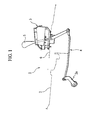
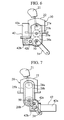
- Figs. 1, 2A and 2B are views each showing an earlier automatic transmission apparatus for a vehicle.
- the automatic transmission apparatus 1 is provided with a shifting mechanism 3 for changing the operating condition of an automatic transmission 2 and a link mechanism 4.
- the shifting mechanism 3 is equipped with a shift lever (shift stick) 5 to be manipulated by a driver.
- shift lever 5 When the driver manipulates the shift lever 5, the movement of the shift lever 5 is transmitted to the automatic transmission 2 through the link mechanism 4 to change a position of the driving range at the automatic transmission 2.
- Reference numeral 6 designates a top of a floor tunnel.
- the automatic transmission apparatus 1 has a problem that the shifting mechanism 3 has to be arranged in a restricted area in a vehicle cabin laboriously. Further, the so-arranged shifting mechanism 3 has the shift lever 5 projecting from the floor tunnel top 6 upward remarkably, which might lose a beautiful sight in view of design.
- an automatic transmission apparatus for a vehicle comprising:
- the manipulating-force assisting device has a driving source formed by the motor, it is possible to alter the magnitude of an assisting force for assisting the driver's manipulation optionally.
- the manipulating-force assisting device it is possible to modify a length of the shift lever, its shape and a manipulating position of the shift lever.
- the shifting mechanism includes a selector casing for accommodating a part of the shift lever therein, the selector casing being provided with a fastening part in the form of a through-pipe extending in a fore-and-aft direction of the vehicle
- the configuration of the rear vent duct can be simplified to reduce the manufacturing cost of the apparatus. Additionally, as the ventilation resistance of the apparatus is reduced, it is possible to improve a quantity of wind and also possible to reduce a level of noise.
- the manipulating-force assisting device may further include a sensor part arranged in the shifting mechanism to detect information about the shift lever and a control unit arranged in the vehicle cabin to generate a drive signal to the motor on basis of the information detected the sensor part.
- the sensor part is arranged in the shifting mechanism, it is possible to detect a load transmitted from the shift lever to a driver's hand, at a position close to the shift lever precisely.
- the shifting mechanism may have an output part associated with the manipulating-force assisting device and the driver's force to manipulating the shift lever is transmitted to the output part through a belt.
- the shifting mechanism may have an output part associated with the manipulating-force assisting device and the driver's force to manipulating the shift lever is transmitted to the output part through a rod.
- an automatic transmission apparatus for a vehicle comprising:
- the assist-force generating unit generates an assist force corresponding to the load detected by the load detecting unit.
- the assist force is combined with a driver's manual manipulating force on the shift lever and transmitted to the automatic transmission. Therefore, even if shortening a length of the shift lever, the manipulation of the shift lever neither gets heavier nor imposes a burden on the driver. Consequently, it becomes possible to increase the degree of freedom in arranging the shift lever.
- the so-shortened shift lever may be arranged in an instrument panel.
- the load detecting unit may be provided in the shift lever.
- a load applied on a driver's hand through the shift lever can be detected, at a position close to the shift lever, by the load detecting unit precisely.
- the assist-force generating unit may be arranged in the driving-range changing mechanism.
- an assist force generated by the assist-force generating unit acts on both the driving-range changing mechanism and the automatic transmission and does not act on the link mechanism. Thus, it is possible to prolong the durability of the link mechanism.
- control unit controls the assist force generating unit so that an assist force generated in changing the driving range between neutral range (N) and forward driving range (D) becomes larger than an assist force generated in changing the driving range to other driving ranges.
- the assist-force generating unit may includes an inhibitor switch that detects a driving range selected by a driver to output a signal corresponding to the driving range selected.
- the control unit allows the load detecting unit to stop detection of a load temporarily until the present driving range is changed to the other driving range.
- the assist-force generating unit generates an assist force in the opposite direction, thereby providing the driver with no feeling of brake in manipulating the shift lever.
- the control unit allows the assist-force generating unit to continue to generate a predetermined assist force until the present driving range is changed to the other driving range.
- control unit allows the assist-force generating unit to generate an assist force while increasing the assist force gradually.
- control unit prohibits the generation of the assist force by the assist-force generating unit until the outputs of the load detecting unit are stabilized.
- the assist-force generating unit generates a designated assist force predetermined in accordance with which of the driving ranges the shift lever does occupy.
- the assist-force generating unit generates a predetermined assist force in accordance with a direction to which the shift lever is manipulated.
- control unit may be provided with a gradient detecting unit for detecting an inclination angle of the vehicle and the assist-force generating unit generates a predetermined assist force in accordance with the inclination angle of the vehicle.
- the assist-force generating unit generates a predetermined assist force in accordance with a condition of the vehicle at a parking range (P) in the driving ranges.
- the automatic transmission apparatus may further comprise a forward driving range (D) including an automatic transmission mode to attain a predetermined gear-speed corresponding to the traveling condition of the vehicle and a manual transmission mode allowing an optional gear-speed to be selected; a mode switching mechanism for switching a transmission mode between the manual transmission mode and the automatic transmission mode by a driver's manipulation of the shift lever; and a manual transmission mode detecting unit for detecting the transmission mode switched to the manual transmission mode, wherein when the transmission mode switched to the manual transmission mode is detected by the manual transmission mode detecting unit, the control unit prohibits the generation of the assist force by the assist-force generating unit.
- D forward driving range
- the control unit prohibits the generation of the assist force by the assist-force generating unit. Therefore, it is possible to prevent the assist-force generating unit from operating by mistake.
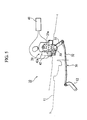
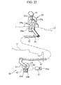
- Fig. 3 is a structural view of an arrangement where an automatic transmission apparatus 10 of the first embodiment is attached to a vehicle body.
- the automatic transmission apparatus 10 includes an automatic transmission 11, a shifting mechanism 20 arranged outside a vehicle cabin to have a shift lever 21 to be manipulated by a driver, a link mechanism 30 arranged outside the vehicle cabin to transmit movements of the shift lever 21 to the automatic transmission 11 and a manipulation-force assisting device 40 arranged in a linking part 50 between the shifting mechanism 20 and the link mechanism 30 to have an electric motor as a driving source.
- the automatic transmission 11 has a function to transmit a driving force of an engine and its rotations to wheels, corresponding to a shift range (driving range) designated by a driver and a travelling situation of the vehicle.
- the shifting mechanism 20 is formed by the shift lever 21 allowing the shift range to be selected, a selector casing 22 for accommodating the shift lever 21, a fastening part 23a formed in one body with the selector casing 21 to fix the mechanism 20 to the vehicle body and an output part 25a for generating the movements of the shift lever 21.
- the shifting mechanism 20 comprises a part positioned inside the vehicle cabin (i.e. part above a floor tunnel top 13) and the other part positioned outside the vehicle cabin (i.e. part below the top 13).
- the shift lever 21 is born by the selector casing 22 through a selector rod 21a.
- the output part 25a is formed by a gear assembly consisting of a first output gear 27a, a second output gear 27b meshing with the gear 27a and a selector output member 26a in the form of a gear meshing with the gear 27b.
- the first output gear 27a is fixed to one end of the selector rod 21.
- the shift lever 21 is associated with the output part 25a.
- the movements of the shift lever 21 are transmitted to the selector rod 21a while converting such straight movements on the lever 21 into rotational motions about the rod 21a. With the engagement among these gears 27a, 27b and 26a, the rotational movements are transmitted from the first output gear 27a to the selector output member (gear) 26a through the second output gear 27b and finally generated from the shifting mechanism 20.
- the link mechanism 30 is provided to transmit the rotational movement of the selector output gear 26a to the automatic transmission 11 and is formed by a link structure, as shown in Fig. 3.
- the link mechanism 30 has a lower lever 31 in the form of a rectangular plate, as an input part.
- the lower lever 31 has one end fastened to the selector output gear 26a at a connecting part 50 and the other end pivotally connected to an end of a transmission rod 32.
- the other end of the transmission rod 32 is pivoted to a manual lever 12 connected with a driving-range changing mechanism of the automatic transmission 11.
- the rotational movements of the selector output gear 26a are transmitted to the lower lever 31, in the form of its pivotal movements.
- the pivotal movements of the lower lever 31 are convened to reciprocating movements of the transmission rod 32. Then, the reciprocating movements of the transmission rod 32 is transmitted to the driving-range changing part of the automatic transmission 11 through the manual lever 12.
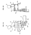
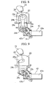
- the manipulating-force assisting device 40 is provided to assist a driver's force to manipulating the shift lever 21, as shown in Figs. 4A and 4B.
- the manipulating-force assisting device 40 comprises a driving part 42, a sensor part 24 and a control unit 41 all connected with each other electrically.
- the driving part 42 is positioned outside the vehicle cabin.
- the driving part 42 includes a motor 42a as a driving source.
- the motor 42a has a rotating shaft fastened to a first motor gear 42b.
- the first motor gear 42b is engaged with a second motor gear 42c.
- the second motor gear 42c meshes with the above connecting part 50.
- the first motor gear 42b rotates. Consequently, the second motor gear 42c is rotated to transmit the driving force of the motor 42a to the connecting part 50, as a force to assist the driver's manipulating force.
- the sensor part 24 is built in the selector rod 21a of the shifting mechanism 20 to detect the position of the shift lever 21, a manipulating force applied thereon, a manipulating amount of the lever 21, a manipulating direction of the lever 21, etc.
- the control unit 41 is arranged in the vehicle cabin to input the above information generated from the sensor part 24 and output command signals corresponding to the information to the driving part 42, thereby controlling the driving force of the motor 42a.
- the control unit 41 calculates a necessary assisting driving force, voltage and current required for the motor 42a to attain the calculated assisting driving force. Then, the so-calculated voltage and current are applied to the motor 42a. With this drive of the motor 42a, the assisting driving force is transmitted to the connecting part 50 through the first motor gear 42b and the second motor gear 42c, whereby the driver's manipulating force can be reduced.
- the automatic transmission apparatus 10 since the automatic transmission apparatus 10 is provided, at the connecting part 50 between the shifting mechanism 20 and the link mechanism 30, with the manipulating-force assisting device 40, it is possible to make the shifting mechanism 20 on the floor tunnel top 13 compact.
- the degree of freedom in mounting the selector casing 22 is increased to realize various decorative forms, for example, an interior decoration having great importance to comfort in the vehicle cabin, an interior decoration having great importance to operability of the shift lever 21, etc.
- the magnitude of the assisting driving force can be changed owing to the adoption of the motor 42a as the driving source. Therefore, it is also possible to alter the driver's manipulating force for every driving range at the shifting mechanism 20. For instance, at both ranges of parking (P) and reverse (R), it may be carried out to reduce an assisting force by the device 40 thereby establishing a driver's manipulating force to be somewhat heavy. On the other hand, at the other driving ranges, the assisting force by the device 40 may be increased to lighten the driver's manipulating force. In this way, it is possible to improve the manipulation feeling of the shift lever 21.
- the manipulating-force assisting device 40 is arranged at the connecting part 50 between the shifting mechanism 20 and the link mechanism 30, even if the same device 40 has a malfunction, it is possible to ensure the change of driving ranges by manipulating the shift lever 21, thereby avoiding traveling inability of vehicle.
- Figs. 5 and 6 show the second embodiment of the invention.
- elements similar to those of the first embodiment are indicated with the same reference numerals, respectively.
- the motor 42a is arranged in the vehicle cabin (above the floor tunnel top).
- the other constituents are similar to those of the first embodiment and therefore, their overlapping descriptions are eliminated.
- the floor tunnel top 13 is subjected to radiant heat from an engine room, exhaust pipes under condition that any wind does not flow on the backside of the vehicle body (e.g. traffic jam, idling stop).
- the motor 42a since the motor 42a is arranged in the vehicle cabin, it is possible to prevent the motor 42a from being exposed to circumstances of high temperature. In other words, according to the embodiment, there is no need to employ an expensive motor having heat-resistant parts, whereby the manufacturing cost of the device 40 can be saved.
- Fig. 7 shows the third embodiment of the invention. Also in this embodiment, elements similar to those of the first embodiment are indicated with the same reference numerals, respectively.
- the third embodiment differs from the first embodiment in the structure of an output part 25b of the shifting mechanism 20. The other constituents are similar to those of the first embodiment and therefore, their overlapping descriptions are eliminated.
- the output part 25b is formed by a transmission structure having a belt 28b.
- a disc-shaped output pulley 28a has its center fastened to the selector rod 21a thereby forming an input part of the output part 25b.
- a selector output member 26b in the form of a disc-shaped pulley is arranged to oppose the output pulley 28a.
- the selector output member (pulley) 26b has its center fastened to the connecting part 50.
- the selector output pulley 26b is associated with the output pulley 28a through the intermediary of the above belt 28b.
- Fig. 8 shows the fourth embodiment of the invention.
- the fourth embodiment differs from the third embodiment in that the shifting mechanism 20 is provided, at an output part 25c thereof, with tensioners 28c for adjusting a tension of the belt 28b. Consequently, even if the using of the shifting mechanism 20 for a long period causes the belt 28b to be expanded, the tensioners 28c serve to maintain a constant tension of the belt 28b. That is, since the adjustment operation of the belt 28b becomes needless, it is possible to improve the capability of the apparatus in terms of maintenance.
- Fig. 9 shows the fifth embodiment of the invention. Also in this embodiment, elements similar to those of the first embodiment are indicated with the same reference numerals, respectively.
- the fifth embodiment differs from the first embodiment in the structure of an output part 25d of the shifting mechanism 20. The other constituents are similar to those of the first embodiment and therefore, their overlapping descriptions are eliminated.
- the output part 25d is formed by a transmission structure having a link mechanism with a rod 29b.
- an output member 29a in the form of a substantial oval plate has its one end fastened to the selector rod 21a thereby forming an input part of the output part 25b.
- a selector output member 26c in the form of a substantial oval plate is arranged to oppose the output member 29a.
- the selector output member 26c has its one end fastened to the connecting part 50.
- the selector output member 26c is connected with the output member 29a through the intermediary of the above rod 29b.
- the rod 29b has its one end rotatably connected with the output member 29a and the other end rotatably connected with the selector output member 26c
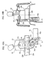
- Figs. 10A and 10B are views showing the sixth embodiment of the invention. Also in this embodiment, elements similar to those of the first embodiment are indicated with the same reference numerals, respectively.
- the sixth embodiment differs from the first embodiment in the shape of a fastening part 23b of the shifting mechanism 20. The other constituents are similar to those of the first embodiment and therefore, their overlapping descriptions are eliminated.
- the fastening part 23b is formed by a through-pipe 23b extending in a fore-and-aft direction of the vehicle.
- the through-pipe 23b is communicated with a not-shown rear vent duct of an air-conditioning unit (also not shown).
- the automatic transmission apparatus is provided, on the side of the vehicle cabin, with a rear bent duct 7 extending along a floor tunnel top 6.
- a rear bent duct 7 Extending from an air-conditioning unit (not shown) on the front side of the vehicle cabin, the rear bent duct 7 is divided, in front of the shifting mechanism 3, into two pieces since the same mechanism 3 occupies a space above the floor tunnel top 3 greatly. Passing through both sides of the shifting mechanism 3, the so-divided duct pieces are gathered to form the rear bent duct 7 again, extending to the side of a rear seat (not shown).
- the earlier automatic transmission apparatus has problems that the shape of the rear bent duct 7 is so complicated as to increase the manufacturing cost of the apparatus and also the ventilation resistance of "air-conditioner" wind.
- the automatic transmission apparatus of this embodiment includes the shift lever 21 having a shortened length and the shifting mechanism 20 having a miniaturized size, the fastening part 23b is provided with the through-pipe 23b mentioned above.
- the through-pipe 23b mentioned above.
- the configuration of the rear vent duct can be simplified to reduce the manufacturing cost of the apparatus. Additionally, as the ventilation resistance of the apparatus is reduced, it is possible to improve a quantity of wind and also possible to reduce a level of noise.
- Fig. 11 is a view showing the seventh embodiment of the invention. Also in this embodiment, elements similar to those of the first embodiment are indicated with the same reference numerals, respectively.
- the seventh embodiment differs from the first embodiment in the shape of a fastening part 23c of the shifting mechanism 20. The other constituents are similar to those of the first embodiment and therefore, their overlapping descriptions are eliminated.
- the fastening part 23c is provided, on a rear-and-lower face thereof, with a through-hole 23C". Further, a motor casing 45a is arranged to enclose a body of the motor 42a. The motor casing 45a is also provided, on its upper part, with a through-hole 45c which is connected with the through-hole 23c" through a hose 45b.
- Figs. 12 to 20 show the eighth embodiment of the invention.
- the shift lever 21 has a length L of e.g. 100 mm and is designed to be short and compact in comparison with the common shift lever having a general length, for example, 250 mm. Owing to the adoption of the so-formed shift lever 21, its projecting amount (length) into the vehicle cabin is relatively small to have less influence on the degree of freedom in terms of interior layout of the vehicle cabin. Further, since the shifting mechanism 20 equipped with the shift lever 21 is compact in size, it is also possible to change the position of the mechanism 20 to another place, for example, an appropriate position on an instrumental panel.
- the lower lever 31 has one end fastened to the selector output gear 26a at the connecting part 50 and the other end pivotally connected to one end of the transmission rod 32.
- the other end of the transmission rod 32 is pivoted to the manual lever 12 connected with the driving-range changing mechanism of the automatic transmission 11.
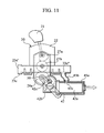
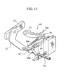
- Fig. 13 shows the above driving-range changing mechanism 60 on the side of the automatic transmission 11.
- the lower end of the manual lever 12 is connected with a rotating shaft 63 carrying a detent plate 64.
- the detent plate 64 is provided, on its upper part, with roots 64b corresponding to four driving ranges (P, R, N, and D). Each root 64b is defined between adjoining cam peaks 64a.
- a detent pin 66 at a tip of a plate spring 65 is adapted so as to engage into the roots 64b in order to keep the position of the selected driving range.
- a driver's forward-and-backward manipulation on the shift lever 21 is transmitted to the detent plate 64 through the transmission rod 32.
- the rotational movement of the detent plate 64 causes the detent pin 66 to climb over one cam peak 64a and engage with the adjacent root 64b. Then, the so-accomplished driving range is maintained by an elastic force of the plate spring 65.
- a force necessary to change one driving range to another driving range is approx.4 Nm, for example.
- a manipulating force of 1.6 kgf producing no problem in manipulating the shift lever.
- the manipulating force is elevated up to the order of 4 kgf, which is too large for a driver to manipulate the shift lever. Therefore, according to the present invention, there is provided the manipulating-force assisting device 40, which comprises the sensor part 24, the driving part 42 and the control unit 41.
- the sensor part 24 is formed by a torque sensor.
- the torque sensor i.e. the sensor part 24
- the torque sensor includes a pair of rotating parts 70 formed on the selector rod 21a and a detecting part 71 for detecting a torsion torque between the rotating pans 70. Since the torque sensor 24 is arranged on the selector rod 21a of the shift lever 21, it is possible to detect an actual torque applied on a driver's hand through the shift lever 21, at a position close to the shift lever 21 precisely. In detail, the torque detected by the torque sensor 24 increases when the detent pin 66 climbs over the cam peak 64a of the detent plate 64.
- the driving part 42 is formed by an actuator.
- the actuator i.e. the driving part 42
- the actuator includes an electric motor 42a and an inhibitor switch 73.
- a gear 42b fixed on a rotating shaft 42aa of the electric motor 42a meshes with the lower gear 26a in the shifting mechanism 20, so that the driving force of the motor 42a can be applied on the lower gear 26a.
- the rotating shaft 22a of the electric motor 22 is rotatable freely with no resistance when it is not energized.
- the inhibitor switch 73 is formed by a contact switch to be turned on when the driving range is selected.
- the inhibitor switch 42a is provided to display the so-selected driving range on a display panel and also generate a signal permitting the start of an engine at non-travelling ranges, such as parking range (P) and neutral range (N).
- the inhibitor switch has been arranged as another component different from the actuator in the common apparatus. While, according to the embodiment, the inhibitor switch 73 is installed in the driving part (actuator) 42. Since there is no need to provide the common inhibitor switch as another component, it is possible to reduce the manufacturing cost of the apparatus.
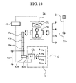
- the control unit (amplifier) 41 is arranged between the electric motor 42a and the torque sensor 24 to control a voltage applied on the motor 42a, corresponding to a torque detected by the torque sensor 24. As shown in Fig. 15, if a load of the shift lever 21 increases, then a detected torque is increased. In such a case, the control unit 41 operates to increase a voltage to be applied on the electric motor 42a in accordance with the increased torque, thereby adding a rotating force of the electric motor 42a to a manual manipulating force of the shift lever 21, as an assist force. Therefore, even if shortening the shift lever 21, there is no increase in a force required to manipulate the shift lever 21. In other words, basically, the rotating force of the electric motor 42a supplements all or part of the torque increased by shortening the shift lever 21.
- the control unit 41 is provided with a control trimmer (volume) 41a that allows the voltage applied on the electric motor 42a to be adjusted manually. That is, by increasing or decreasing the voltage applied on the motor 42a according to differences between individuals, such as a manipulator's body build, it is possible to adjust a force necessary to manipulate the shift lever 21 to the optimum level.
- a control trimmer (volume) 41a that allows the voltage applied on the electric motor 42a to be adjusted manually. That is, by increasing or decreasing the voltage applied on the motor 42a according to differences between individuals, such as a manipulator's body build, it is possible to adjust a force necessary to manipulate the shift lever 21 to the optimum level.
- assist forces by the motor 71 are not identical but different from each other among the driving ranges, providing variations with respect to feeling of manipulation. That is, as shown in Fig. 16, there is established, between the parking range (P) and the reverse range (R), a manipulating force of 1.6 kgf which is similar to that of the common long shift lever in order to prompt a driver's reliable manipulation while allowing the driver to feel a certain measure of resistance from the shift lever 21. Similarly, a manipulating force somewhat smaller than 1.6 kgf is established between the reverse range (R) and the neutral range (N). On the assumption of frequent changes, there is established a manipulating force of 1 kgf or so, between the neutral range (N) and the forward driving range (D).
- the motor 42a of this embodiment has a structure allowing free rotation with no resistance when the motor 42a is supplied with no electricity, the manipulating of the shift lever 21 could be insured, heavier though it becomes, even if the apparatus has a trouble, for example, malfunction of a battery, abnormal operation of the control unit 41, etc. This means that there is no need to measure disfunctional operation of the apparatus, bringing significant advantages.
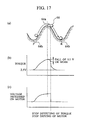
- a diagram part (a) illustrates a movement of the detent pin 66 that climbs over one cam peak 64a to move from the parking range (P) to the reverse range (R). It is noted that a torque detected by the torque sensor 24 exhibits a characteristic curve similar to the profile of the cam peak 64a.
- the torque sensor 24 of this embodiment generates a voltage of 2.5V in its neural condition. As shown in a diagram part (b) of Fig. 17, the sensor 24 generates a voltage of 2.5V (as base voltage) even when the sensor 24 does not detect a torque.
- a situation having a detected torque (dv / dt) more than 3 continues for 15 ns. (nano-second) at least, then it is recognized that such a situation is an action to climb over the cam peak 64a.
- the torque sensor 24 is detecting a positive torque, as shown in a diagram part (c) of Fig. 17, a voltage corresponding to the positive torque is impressed on the motor 42a, a necessary assist force is combined with a manual manipulating force of the shift lever 21.
- the detent pin 66 is led into the cam groove 64b on the side of the adjacent reverse range (R) by an elastic force of the plate spring 65, so that the torque sensor 24 detects a negative torque in the opposite direction to the transmitting direction of the manipulating force.
- the electric motor would rotate in the opposite direction thereby to exert a brake-feeling with a jerk on the manipulation of the shift lever 21. Therefore, according to this embodiment, when the torque sensor 24 detects a negative torque (i.e. reduction of 0.2 V or more in the reverse direction), it is judged that the above leading (drawing) has started. Then, it is executed to stop both detecting of torque by the torque sensor 24 and rotating of the motor 42a until the inhibitor switch 73 detects the reverse range (R). Accordingly, there is no possibility that the manipulation of the shift lever 21 is accompanied with a brake feeling.
- the reading operation of the torque sensor 24 is prohibited from reading a torque for a period from the power-ON by manipulating the ignition till a lapse of 150 ms. That is, since a time required for the torque sensor 24 to rise perfectly is 130 ms, the torque sensor 24 has already raised itself up at the beginning of reading a torque, whereby the glitch of the electric motor 42a can be prevented.
- the activating period of the torque sensor 24 is prolonged for 150 ms. That is, the torque sensor 24 is powered off after the motor 42a has been powered off and therefore, it is possible to prevent the glitch of the electric motor 42a.
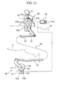
- Fig. 21 shows the ninth embodiment of the invention.
- the driving part 18 in the form of an actuator is arranged on the side of the driving-range changing mechanism 60.
- a gear 43 is fixed to the rotating shaft 63 secured to the manual lever 12 and is engaged with the gear 42b on the rotating shaft 42c of the motor 42.
- the assisting force produced by the motor 42a acts on the driving-range changing mechanism 60 and also the automatic transmission 11 and does not act on the transmission rod 32. Therefore, it is possible to improve the durability of the transmission rod 32.
- Fig. 22 shows the tenth embodiment of the invention.
- the driving part 18 not only the driving part 18 but also the torque sensor 24 is arranged on the side of the driving-range changing mechanism 60. This arrangement would be suitable in a situation such that the shifting mechanism 20 and its circumference could not provide spaces for the torque sensor 24 and the driving part 18.
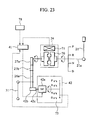
- Fig. 23 shows the eleventh embodiment of the invention.
- a plurality of assist-torque maps are installed in the control unit 41 in order to control the operation of the electric motor 42a.
- driving-range change torques required in changing one driving range to the other one are different from each other for every driving ranges. This is because loads generated in changing a gear-engagement in the driving-range changing mechanism 60 are different from each other for every driving ranges, besides loads produced when the detent pin 66 climbs over the cam peak 64a of the detent plate 64.
- the driving-range changing torque necessary to shift the shift lever 21 from the parking range (P) to the reverse range (R) changes by whether the vehicle at the parking range (P) has been parked on a flat road or gradient road.
- the driving-range changing torque further changes corresponding to a slope of the gradient road.
- a parking pole 76 interrupts the rotation of a parking gear 76a through a cam plate 77 to lock up driving wheels (not shown).
- the load of a vehicle weight is applied on the cam plate 77 so as to lock up the driving wheels corresponding to a slope of the gradient road, thereby functioning as a force engaging the parking pole 76.
- the same torque in case of parking the vehicle on the gradient road becomes larger than that in case of parking the vehicle on the flat road, requiring a driver's large force to manipulate the shift lever 21.
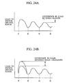
- the control unit 41 is provided, between the adjoining driving ranges, with an assist torque map to reduce a manipulating force for the shift lever 21 to a designated manipulating force. Further, the unit 41 is provided, corresponding to a gradient of the vehicle, with an additional assist torque map to reduce a manipulating force, which is required for the shift lever 21 to change its position from the parking range (P) to the other driving range, to a designated manipulating force.
- a load A of Fig. 25 is applied on the shift lever 21 to change its position from the parking range (P) to the other driving range. While, in case of a gradient road of 15 %, a load B (Fig. 21) is applied to the shift lever 21. Therefore, a line of "P ⁇ R (15% gradient)" is selected from the assist torque map to generate an assisting force, whereby the shift lever 21 can be operated with a load similar to that in case of parking the vehicle on a flat road.
- Fig. 26 it is performed to input both a range-position signal generated from the inhibitor switch 73 and a road-gradient signal generated from a gradient sensor 78, into the control unit 41. Then, the present position of the shift lever 21 and its manipulating direction are detected by a torque signal generated from the torque sensor 24 in manipulating the shift lever 21. Corresponding to the so-detected range position and manipulating direction of the shift lever 21, it is carried out to select an appropriate assist torque map from a plurality of assist torque maps in Fig. 25.
- a designated current corresponding to the so-calculated assisting force is generated from the control unit 41 to the driving part 42 thereby producing the above assisting force.
- the shift lever 21 when the shift lever 21 is at the parking range (P), it is carried out to calculate a road gradient by the road-gradient signal and further select an appropriate map from the assist torque maps for the parking range (P). If there is no appropriate assist torque map at the a gradient sensor 78, then two assist torque maps above and below the calculated road gradient are selected for supplement to calculate an assist force in charge of the driving part 42 in accordance with the torque signal.
- assist torque maps each having an assist torque changeable linearly in accordance with a load are employed in the above mentioned embodiment, there can be used assist torque maps each resulting by adding a constant value to an assist torque map for the flat road corresponding to a road gradient. Alternatively, it is possible to use a map obtained by experimental values.
- the above motor 42b may be replaced with an electric motor having an established output torque.
- the control unit 41 may be provided, in its circuit, with a fuse. Then, even if an excess current flows the motor without discretion, it is possible to prevent the shift lever 21 from being shifted against a driver's will due to an assisting force generated by the drive part 42.
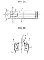
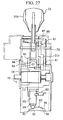
- Figs. 27 and 28 show the twelfth embodiment of the invention.
- an automatic transmission apparatus is provided with a forward driving range (D) including a manual transmission mode allowing an optional gear-speed to be selected and an automatic transmission mode to attain a predetermined gear-speed corresponding to the travelling condition of the vehicle.
- D forward driving range
- the automatic transmission apparatus of the embodiment includes a mode switching mechanism 79 to switch the operation of the apparatus between the manual transmission mode and the automatic transmission mode and a "manual transmission mode" detecting unit 80 to detect the apparatus in the manual transmission mode.
- the shift lever 21 is formed by a manipulating lever part 21b and a shift lever part 21c.
- the manipulating lever part 21b is joined to the shift lever part 21c.
- the manipulating lever part 21b is maintained in its upright posture (i.e. automatic transmitting position) in view of the apparatus in a fore-and-aft direction of the vehicle. In this state, one driving range is changed to the other driving range.
- the manipulating lever part 21b is inclined in view of the apparatus in the fore-and-aft direction of the vehicle and maintained in its manual transmitting position. In this state, one gear-speed is changed to the other gear-speed.
- the mode switching mechanism 79 is formed by a swing support 81 for pivotally supporting the manipulating lever part 21b, a clutch 82 for connecting the lever part 21b with the shift lever part 21c certainly and a cam part 83 for holding the lever part 21b at either the automatic transmitting position or the manual transmitting position.
- a sensor-side connecting part 84 in one body with the torque sensor 24 is pivotally connected with a lever-side connecting part 85 in one body with the manipulating lever part 21b, through a round bar pin 86.
- the lever part 21b is connected with the shift lever part 21c when the automatic transmission apparatus is in the automatic transmitting mode and when changing one driving range to the other driving range, thereby preventing a saccadic movement between the lever part 21b and the lever part 21c.
- the cam part 83 is formed by a ball spring 89 attached to the lower end of the manipulating lever part 21b and a cam top 90. At the tip of the ball spring 89, a ball part 91 is urged against the cam top 90 by a spring 92. Under such an urging condition, the manipulating lever part 21b is supported on either a slanted face 93 on the side of the automatic transmission or another slanted face 94 on the side of the manual transmission.
- the ball part 91 In order to switch the transmission mode (between the automatic transmission mode and the manual transmission mode), the ball part 91 has to climb over a peak of the cam top 90 while repelling a force of the spring 92. Therefore, the manipulating lever part 21b is maintained in either the automatic transmission mode or the manual transmission mode stably.
- a mode switch 80 is arranged in the vicinity of the lower end of the manipulating lever part 21b. In operation, the switch 80 is switched ON when the apparatus is in the automatic transmission mode. The switch 80 is switched OFF when the apparatus is in the manual transmission mode.
Landscapes
- Engineering & Computer Science (AREA)
- General Engineering & Computer Science (AREA)
- Mechanical Engineering (AREA)
- Gear-Shifting Mechanisms (AREA)
- Arrangement Or Mounting Of Control Devices For Change-Speed Gearing (AREA)
- Control Of Transmission Device (AREA)
Applications Claiming Priority (4)
| Application Number | Priority Date | Filing Date | Title |
|---|---|---|---|
| JP2002033037 | 2002-02-08 | ||
| JP2002033037 | 2002-02-08 | ||
| JP2002167371 | 2002-06-07 | ||
| JP2002167371A JP2003301942A (ja) | 2002-02-08 | 2002-06-07 | 車両用自動変速装置 |
Publications (1)
| Publication Number | Publication Date |
|---|---|
| EP1335155A2 true EP1335155A2 (fr) | 2003-08-13 |
Family
ID=27615750
Family Applications (1)
| Application Number | Title | Priority Date | Filing Date |
|---|---|---|---|
| EP03001626A Withdrawn EP1335155A2 (fr) | 2002-02-08 | 2003-01-24 | Dispositif de transmission automatique de véhicule |
Country Status (3)
| Country | Link |
|---|---|
| US (1) | US7013748B2 (fr) |
| EP (1) | EP1335155A2 (fr) |
| JP (1) | JP2003301942A (fr) |
Cited By (11)
| Publication number | Priority date | Publication date | Assignee | Title |
|---|---|---|---|---|
| EP1561973A1 (fr) * | 2004-02-09 | 2005-08-10 | Calsonic Kansei Corporation | Levier de commande avec connection mécanique à la transmission avec assistance servo |
| WO2006050773A1 (fr) * | 2004-11-09 | 2006-05-18 | Voith Turbo Gmbh & Co.Kg | Systeme d'actionnement pour commander le changement de vitesse dans une boite de vitesses de vehicule automobile |
| EP1666772A1 (fr) * | 2004-08-23 | 2006-06-07 | Calsonic Kansei Corporation | Transmission automatique pour vehicule et son levier d'actionnement |
| EP2023020A1 (fr) * | 2007-08-10 | 2009-02-11 | GM Global Technology Operations, Inc. | Engrenage doté d'une assistance à la commutation et d'une protection en cas de panne |
| EP1591697A3 (fr) * | 2004-04-28 | 2009-12-30 | Calsonic Kansei Corporation | Dispositif de sélection de position d'opération pour une transmission automatique |
| EP1598577A3 (fr) * | 2004-05-21 | 2009-12-30 | Calsonic Kansei Corporation | Dispositif de sélection de position d'opération pour une transmission automatique |
| CN102661385A (zh) * | 2012-05-03 | 2012-09-12 | 浙江科技学院 | 一种手自联动换档装置及其控制方法 |
| CN102661384A (zh) * | 2012-05-03 | 2012-09-12 | 浙江科技学院 | 一种新型手自联动换档装置及其控制方法 |
| CN104421418A (zh) * | 2013-09-10 | 2015-03-18 | 通用汽车环球科技运作有限责任公司 | 用于变速器的换挡杆系组件 |
| CN105573348A (zh) * | 2014-10-29 | 2016-05-11 | 通用汽车环球科技运作有限责任公司 | 多位置致动器 |
| US11434990B2 (en) * | 2019-12-25 | 2022-09-06 | Mazda Motor Corporation | Vehicle shift device with lateral and longitudinal motion |
Families Citing this family (22)
| Publication number | Priority date | Publication date | Assignee | Title |
|---|---|---|---|---|
| JP3792586B2 (ja) * | 2002-03-12 | 2006-07-05 | 本田技研工業株式会社 | 車両の変速操作装置 |
| JP2004203088A (ja) * | 2002-12-24 | 2004-07-22 | Calsonic Kansei Corp | 車両用自動変速装置 |
| DE602004001880T2 (de) * | 2003-01-07 | 2007-04-05 | Calsonic Kansei Corp. | Wählhebel für Automatikgetriebe |
| JP4487516B2 (ja) * | 2003-08-26 | 2010-06-23 | トヨタ自動車株式会社 | 車両用パーキングロック装置 |
| JP2005273819A (ja) * | 2004-03-25 | 2005-10-06 | Atsumi Tec:Kk | 車両用自動変速操作装置 |
| JP4543230B2 (ja) * | 2004-04-19 | 2010-09-15 | 日産自動車株式会社 | 自動変速機のセレクトアシスト装置 |
| JP4255889B2 (ja) | 2004-07-07 | 2009-04-15 | 日産自動車株式会社 | 車両用自動変速装置のアシスト制御方法 |
| JP4781650B2 (ja) * | 2004-09-17 | 2011-09-28 | 川崎重工業株式会社 | 車両のシフトレバー装置 |
| EP1640641A2 (fr) | 2004-09-24 | 2006-03-29 | Calsonic Kansei Corporation | Boîte de vitesses automatiques pour véhicule |
| JP2006138390A (ja) * | 2004-11-11 | 2006-06-01 | Calsonic Kansei Corp | 車両用自動変速装置 |
| JP2006125545A (ja) * | 2004-10-29 | 2006-05-18 | Calsonic Kansei Corp | 自動変速機のセレクトアシスト装置 |
| JP2007170545A (ja) * | 2005-12-22 | 2007-07-05 | Denso Corp | シフトレンジ切換装置 |
| ES2357411T3 (es) * | 2005-12-23 | 2011-04-26 | Innovius B.V. | Dispositivo de cambio de engranaje para aplicaciones motorizadas. |
| ATE455924T1 (de) * | 2007-03-12 | 2010-02-15 | Delphi Tech Inc | Türbetätigungsverfahren |
| DE102007062824A1 (de) * | 2007-12-21 | 2009-06-25 | Zf Friedrichshafen Ag | Betätigungseinrichtung mit Sperrwalze |
| WO2011133864A2 (fr) | 2010-04-22 | 2011-10-27 | Milwaukee Electric Tool Corporation | Lame de scie |
| US10189099B2 (en) | 2010-04-22 | 2019-01-29 | Milwaukee Electric Tool Corporation | Saw Blade |
| KR101283597B1 (ko) | 2011-10-14 | 2013-07-05 | 현대자동차주식회사 | 수동변속기의 변속 조작장치 |
| EP3832169A1 (fr) * | 2012-10-31 | 2021-06-09 | Parker-Hannifin Corporation | Système de commande d'engrenage pour atténuer les vibrations |
| US9139170B2 (en) * | 2013-10-29 | 2015-09-22 | GM Global Technology Operations LLC | Hinge pillar assembly |
| US11413693B2 (en) | 2017-05-16 | 2022-08-16 | Milwaukee Electric Tool Corporation | Saw blade |
| CN114962619B (zh) * | 2022-06-28 | 2024-03-29 | 江苏盛海智能科技有限公司 | 一种基于手动变速箱改装的自动变速箱 |
Citations (2)
| Publication number | Priority date | Publication date | Assignee | Title |
|---|---|---|---|---|
| JPH09323559A (ja) | 1996-06-05 | 1997-12-16 | Nissan Motor Co Ltd | 自動変速機の操作装置 |
| JP2001339776A (ja) | 2000-05-25 | 2001-12-07 | Yamatake Corp | データ収集装置 |
Family Cites Families (13)
| Publication number | Priority date | Publication date | Assignee | Title |
|---|---|---|---|---|
| US3603167A (en) * | 1970-06-11 | 1971-09-07 | Ametek Inc | Control device |
| US3686967A (en) * | 1970-10-06 | 1972-08-29 | Verson Mfg Co | Plural speed transmission system |
| DE3031643A1 (de) * | 1980-08-22 | 1982-04-01 | SWF-Spezialfabrik für Autozubehör Gustav Rau GmbH, 7120 Bietigheim-Bissingen | Servoeinrichtung, insbesondere zur bremskraftverstaerkung in einem kraftfahrzeug |
| US4483682A (en) * | 1982-10-12 | 1984-11-20 | Outboard Marine Corporation | Linear power assist mechanism |
| EP0898530B1 (fr) * | 1996-05-21 | 2001-12-05 | Bayerische Motoren Werke Aktiengesellschaft, Patentabteilung AJ-3 | Systeme de frein de stationnement |
| DE19636506B4 (de) * | 1996-09-09 | 2005-08-11 | Daimlerchrysler Ag | Schaltvorrichtung für ein Gangwechselgetriebe eines Kraftfahrzeuges |
| US5967252A (en) * | 1997-09-29 | 1999-10-19 | Uri Rapoport | Push button actuation system for ATV transmission |
| US6321612B1 (en) * | 1998-04-14 | 2001-11-27 | Mannesmann Sachs Ag | Actuating mechanism for the automatic operation of a gear-shift in a transmission |
| US6378393B1 (en) * | 2000-05-19 | 2002-04-30 | Kelsey-Hayes Company | Method and apparatus for manually shifting an electronically controlled transmission |
| DE50113489D1 (de) * | 2000-07-14 | 2008-03-06 | Trw Automotive Electron & Comp | Betätigungsvorrichtung für die Schaltwelle eines Automatikgetriebes |
| JP3970507B2 (ja) * | 2000-08-18 | 2007-09-05 | アルプス電気株式会社 | バイワイヤ方式の車両用シフトレバー装置 |
| US6904823B2 (en) * | 2002-04-03 | 2005-06-14 | Immersion Corporation | Haptic shifting devices |
| KR100488740B1 (ko) * | 2003-08-27 | 2005-05-11 | 현대자동차주식회사 | 차량용 시프트 바이 와이어 시스템의 시프팅 장치 |
-
2002
- 2002-06-07 JP JP2002167371A patent/JP2003301942A/ja active Pending
-
2003
- 2003-01-24 US US10/350,359 patent/US7013748B2/en not_active Expired - Fee Related
- 2003-01-24 EP EP03001626A patent/EP1335155A2/fr not_active Withdrawn
Patent Citations (2)
| Publication number | Priority date | Publication date | Assignee | Title |
|---|---|---|---|---|
| JPH09323559A (ja) | 1996-06-05 | 1997-12-16 | Nissan Motor Co Ltd | 自動変速機の操作装置 |
| JP2001339776A (ja) | 2000-05-25 | 2001-12-07 | Yamatake Corp | データ収集装置 |
Cited By (17)
| Publication number | Priority date | Publication date | Assignee | Title |
|---|---|---|---|---|
| EP1561973A1 (fr) * | 2004-02-09 | 2005-08-10 | Calsonic Kansei Corporation | Levier de commande avec connection mécanique à la transmission avec assistance servo |
| US7243567B2 (en) | 2004-02-09 | 2007-07-17 | Calsonic Kansei Corporation | Operating position select device for automatic transmission |
| EP1591697A3 (fr) * | 2004-04-28 | 2009-12-30 | Calsonic Kansei Corporation | Dispositif de sélection de position d'opération pour une transmission automatique |
| EP1598577A3 (fr) * | 2004-05-21 | 2009-12-30 | Calsonic Kansei Corporation | Dispositif de sélection de position d'opération pour une transmission automatique |
| EP1666772A1 (fr) * | 2004-08-23 | 2006-06-07 | Calsonic Kansei Corporation | Transmission automatique pour vehicule et son levier d'actionnement |
| WO2006050773A1 (fr) * | 2004-11-09 | 2006-05-18 | Voith Turbo Gmbh & Co.Kg | Systeme d'actionnement pour commander le changement de vitesse dans une boite de vitesses de vehicule automobile |
| EP2023020A1 (fr) * | 2007-08-10 | 2009-02-11 | GM Global Technology Operations, Inc. | Engrenage doté d'une assistance à la commutation et d'une protection en cas de panne |
| CN101363541B (zh) * | 2007-08-10 | 2013-03-06 | Gm全球科技运作股份有限公司 | 有换挡支持和故障安全性装置的变速器 |
| CN102661384A (zh) * | 2012-05-03 | 2012-09-12 | 浙江科技学院 | 一种新型手自联动换档装置及其控制方法 |
| CN102661385A (zh) * | 2012-05-03 | 2012-09-12 | 浙江科技学院 | 一种手自联动换档装置及其控制方法 |
| CN102661384B (zh) * | 2012-05-03 | 2014-10-22 | 浙江科技学院 | 一种新型手自联动换档装置及其控制方法 |
| CN102661385B (zh) * | 2012-05-03 | 2014-12-03 | 浙江科技学院 | 一种手自联动换档装置及其控制方法 |
| CN104421418A (zh) * | 2013-09-10 | 2015-03-18 | 通用汽车环球科技运作有限责任公司 | 用于变速器的换挡杆系组件 |
| CN104421418B (zh) * | 2013-09-10 | 2017-04-12 | 通用汽车环球科技运作有限责任公司 | 用于变速器的换挡杆系组件 |
| CN105573348A (zh) * | 2014-10-29 | 2016-05-11 | 通用汽车环球科技运作有限责任公司 | 多位置致动器 |
| CN105573348B (zh) * | 2014-10-29 | 2018-07-13 | 通用汽车环球科技运作有限责任公司 | 多位置致动器 |
| US11434990B2 (en) * | 2019-12-25 | 2022-09-06 | Mazda Motor Corporation | Vehicle shift device with lateral and longitudinal motion |
Also Published As
| Publication number | Publication date |
|---|---|
| US7013748B2 (en) | 2006-03-21 |
| JP2003301942A (ja) | 2003-10-24 |
| US20040016314A1 (en) | 2004-01-29 |
Similar Documents
| Publication | Publication Date | Title |
|---|---|---|
| US7013748B2 (en) | Automatic transmission apparatus for vehicle | |
| RU2660235C2 (ru) | Способ (варианты ) эксплуатации транспортного средства | |
| JP2006070979A5 (fr) | ||
| ES2400822T3 (es) | Sistema de control de la transmisión | |
| JP3936854B2 (ja) | 作業車両の変速装置 | |
| JP6146391B2 (ja) | トラクタの作業制御装置 | |
| JP4659374B2 (ja) | 自動二輪車の制御装置 | |
| JP3306500B2 (ja) | 圃場作業機の制御装置 | |
| JP2001280492A (ja) | 無段変速機の制御方法 | |
| JP2004230952A (ja) | シフトバイワイヤシステムのフェールセーフ構造 | |
| JP7352859B2 (ja) | 車両の変速操作装置 | |
| JPH07280086A (ja) | ギヤ変換機 | |
| KR101031057B1 (ko) | 차량용 능동 전륜 조향 시스템 | |
| ES2325273T3 (es) | Caja de velocidades robotizada para vehiculos motorizados, en particular para personas discapacitadas. | |
| JP4131671B2 (ja) | 自動変速機のセレクトアシスト装置 | |
| JP2005255073A (ja) | コンバインのトランスミッション | |
| JPH0554863U (ja) | オートチェンジ | |
| JP2002036900A (ja) | 作業車 | |
| JP4379065B2 (ja) | 無段変速装置 | |
| JP2001065674A (ja) | トラクタの走行変速装置 | |
| JP3672439B2 (ja) | 作業車 | |
| JPH0614107Y2 (ja) | 自動変速機の制御装置 | |
| JP2583684Y2 (ja) | 自動車用変速操作装置 | |
| KR100625342B1 (ko) | 자동차 변속레버의 높낮이 자동조절장치 | |
| JP3527102B2 (ja) | 作業車 |
Legal Events
| Date | Code | Title | Description |
|---|---|---|---|
| PUAI | Public reference made under article 153(3) epc to a published international application that has entered the european phase |
Free format text: ORIGINAL CODE: 0009012 |
|
| AK | Designated contracting states |
Designated state(s): AT BE BG CH CY CZ DE DK EE ES FI FR GB GR HU IE IT LI LU MC NL PT SE SI SK TR |
|
| AX | Request for extension of the european patent |
Extension state: AL LT LV MK RO |
|
| STAA | Information on the status of an ep patent application or granted ep patent |
Free format text: STATUS: THE APPLICATION HAS BEEN WITHDRAWN |
|
| 18W | Application withdrawn |
Effective date: 20080318 |