EP1335337A1 - Système antivol commandé et programmé par ordinateur ou par téléphone, avec identification de l'état de chaque module de protection - Google Patents
Système antivol commandé et programmé par ordinateur ou par téléphone, avec identification de l'état de chaque module de protection Download PDFInfo
- Publication number
- EP1335337A1 EP1335337A1 EP02425060A EP02425060A EP1335337A1 EP 1335337 A1 EP1335337 A1 EP 1335337A1 EP 02425060 A EP02425060 A EP 02425060A EP 02425060 A EP02425060 A EP 02425060A EP 1335337 A1 EP1335337 A1 EP 1335337A1
- Authority
- EP
- European Patent Office
- Prior art keywords
- antitheft
- central
- plant
- protection
- fittings
- Prior art date
- Legal status (The legal status is an assumption and is not a legal conclusion. Google has not performed a legal analysis and makes no representation as to the accuracy of the status listed.)
- Ceased
Links
Images


Classifications
-
- G—PHYSICS
- G08—SIGNALLING
- G08B—SIGNALLING SYSTEMS, e.g. PERSONAL CALLING SYSTEMS; ORDER TELEGRAPHS; ALARM SYSTEMS
- G08B25/00—Alarm systems in which the location of the alarm condition is signalled to a central station, e.g. fire or police telegraphic systems
- G08B25/008—Alarm setting and unsetting, i.e. arming or disarming of the security system
-
- G—PHYSICS
- G08—SIGNALLING
- G08B—SIGNALLING SYSTEMS, e.g. PERSONAL CALLING SYSTEMS; ORDER TELEGRAPHS; ALARM SYSTEMS
- G08B13/00—Burglar, theft or intruder alarms
- G08B13/18—Actuation by interference with heat, light, or radiation of shorter wavelength; Actuation by intruding sources of heat, light, or radiation of shorter wavelength
- G08B13/189—Actuation by interference with heat, light, or radiation of shorter wavelength; Actuation by intruding sources of heat, light, or radiation of shorter wavelength using passive radiation detection systems
- G08B13/194—Actuation by interference with heat, light, or radiation of shorter wavelength; Actuation by intruding sources of heat, light, or radiation of shorter wavelength using passive radiation detection systems using image scanning and comparing systems
- G08B13/196—Actuation by interference with heat, light, or radiation of shorter wavelength; Actuation by intruding sources of heat, light, or radiation of shorter wavelength using passive radiation detection systems using image scanning and comparing systems using television cameras
- G08B13/19634—Electrical details of the system, e.g. component blocks for carrying out specific functions
-
- G—PHYSICS
- G08—SIGNALLING
- G08B—SIGNALLING SYSTEMS, e.g. PERSONAL CALLING SYSTEMS; ORDER TELEGRAPHS; ALARM SYSTEMS
- G08B13/00—Burglar, theft or intruder alarms
- G08B13/18—Actuation by interference with heat, light, or radiation of shorter wavelength; Actuation by intruding sources of heat, light, or radiation of shorter wavelength
- G08B13/189—Actuation by interference with heat, light, or radiation of shorter wavelength; Actuation by intruding sources of heat, light, or radiation of shorter wavelength using passive radiation detection systems
- G08B13/194—Actuation by interference with heat, light, or radiation of shorter wavelength; Actuation by intruding sources of heat, light, or radiation of shorter wavelength using passive radiation detection systems using image scanning and comparing systems
- G08B13/196—Actuation by interference with heat, light, or radiation of shorter wavelength; Actuation by intruding sources of heat, light, or radiation of shorter wavelength using passive radiation detection systems using image scanning and comparing systems using television cameras
- G08B13/19654—Details concerning communication with a camera
- G08B13/19658—Telephone systems used to communicate with a camera, e.g. PSTN, GSM, POTS
-
- G—PHYSICS
- G08—SIGNALLING
- G08B—SIGNALLING SYSTEMS, e.g. PERSONAL CALLING SYSTEMS; ORDER TELEGRAPHS; ALARM SYSTEMS
- G08B13/00—Burglar, theft or intruder alarms
- G08B13/18—Actuation by interference with heat, light, or radiation of shorter wavelength; Actuation by intruding sources of heat, light, or radiation of shorter wavelength
- G08B13/189—Actuation by interference with heat, light, or radiation of shorter wavelength; Actuation by intruding sources of heat, light, or radiation of shorter wavelength using passive radiation detection systems
- G08B13/194—Actuation by interference with heat, light, or radiation of shorter wavelength; Actuation by intruding sources of heat, light, or radiation of shorter wavelength using passive radiation detection systems using image scanning and comparing systems
- G08B13/196—Actuation by interference with heat, light, or radiation of shorter wavelength; Actuation by intruding sources of heat, light, or radiation of shorter wavelength using passive radiation detection systems using image scanning and comparing systems using television cameras
- G08B13/19678—User interface
- G08B13/19684—Portable terminal, e.g. mobile phone, used for viewing video remotely
-
- G—PHYSICS
- G08—SIGNALLING
- G08B—SIGNALLING SYSTEMS, e.g. PERSONAL CALLING SYSTEMS; ORDER TELEGRAPHS; ALARM SYSTEMS
- G08B25/00—Alarm systems in which the location of the alarm condition is signalled to a central station, e.g. fire or police telegraphic systems
- G08B25/003—Address allocation methods and details
Definitions
- This invention relates to the field of antitheft plants for civil and industrial buildings.
- this invention relates to an antitheft plant including a central control or alarm unit and protection fittings.
- protection fittings the devices or peripheral elements of the antitheft plant are meant hereinafter, that perform the antitheft functions, such as for instance sensors or detectors, alarm devices, actuators, e.g. alarm actators.
- This invention takes its steps from considering that such solutions, however, turn out to be insufficient, and gives itself the object of providing an antitheft plant that can be monitored element by element from a central unit, i.e. an antitheft plant wherein the state of each single protection fitting, which is part thereof, is analysed and suitably displayed.
- the antitheft plant of this invention is based on a programming of single protection fittings, which is carried out before installing the antitheft plant itself.
- each protection fitting is associated an identification code, which is stored in non-volatile memory means, such as for instance an electrically erasable programmable read only memory, which also store it in the absence of electric power supply to the antitheft plant.
- the central control unit is presented in the form of a cellular phone, having a display, for instance a dot-matrix display, accompanied by an alphanumeric keypad having function keys, for instance three function keys, performing functions that vary in correspondence with response areas of the display.
- a suitably large size is envisaged to the object of easily using the keypad thereof and of easily reading the display thereof.
- the insertion of the identification codes above and the texts for describing the corresponding protection fittings is carried out as if a message were fingered on a cellular phone.
- the central control unit is in electric communication with the protection fittings, for instance by radio or by wire.
- This invention particularly envisages a connection of the central control unit with the protection fittings by a two-wire transmission line, having an output line from and a response line to the central control unit, on which two-wire transmission line the protection fittings are connected in parallel.
- the programming procedure is similar to the structure adopted in known programming languages, such as for instance BASIC, wherein the control line is marked by a number that identifies the memory area occupied. Before each line a code, for instance a decimal code, is inserted, in numeric progression. In the same modality a programming is carried out of the protection fittings of the antitheft plant of this invention.
- the identification code is provided by the central control unit and the description of the protection fitting is fingered by the installer. For instance:
- the identification code associated with each description is stored, for instance in a binary format.
- the identification codes of all protection fittings have been stored, one proceeds with the installation thereof, positioning them in the areas whereto the relevant associated description relates.
- the central control unit When the plant is supplied with electric power, the central control unit performs a state checking stage (as takes place in personal computers at the moment of the powering up thereof, when the programme present in BIOS polls all connected peripheral devices, verifying the correctness of the operation thereof). In the same way, the central control unit of the antitheft device of this invention proceeds with checking that the protection fittings are all connected, checking the state of connection and correct operation thereof, through scanning of the stored codes.
- each protection fitting includes an internal circuit which fetches the identification code from the transmission line from the central control unit, and compares it with the one present in the E 2 PROM memory thereof above. If the codes are equal, the internal circuit communicates to the central control unit the state of the protection fitting through the response line. In the opposite case, the circuit sets an output thereof to a high-impedence state to allow the subsequent protection fitting to give his response.
- the alarm actuators are endowed with internal programmes that detect the disconnection thereof from the transmission lines in case of shearing or of a shortcircuit thereof, operating the actuation of the alarms. It is particularly envisaged the use of relay actuators.
- this invention particularly envisages the use of devices that are able to communicate in a duplex or full-duplex way, i.e. with a data exchange in two directions simultaneously.
- the user device so can be directly programmed from the central alarm unit. For instance, one can programme a heating plant by introducing from the central alarm unit a turn-on/off timetable, or one can programme a lighting network.
- this invention further envisages to equip the antitheft plant with a plant of closed-circuit monitoring cameras, managed through the central control unit by actuating only one interested camera at a time.
- Video signals from the cameras can be connected in parallel onto a coaxial cable, eliminating the problem of having to be able to bring all video signals of the cameras to a selection circuit, saving large quantities of cable and space.
- this invention takes its steps from considering the possibilities offered by Internet network, by electronic mail services and by the cellular phone network, and by the large and growing spreading thereof. Then, this invention gives itself the further object, and this also forms the teaching of this invention, of being able to remotely input instructions into the antitheft device, through electronic mail messages and/or cellular phone text messages SMS (Short Message Service), i.e. of using a computer, particularly a personal computer, or a cellular phone as control consoles of the antitheft plant.
- SMS Short Message Service
- Such an object is reached by equipping the central alarm unit with a modem for a communication with an Internet/electronic mail server, or with a transceiver, for a communication with cellular phone network.
- Still a further object of this invention is that of being able to monitor an antitheft plant and to manage the central alarm unit thereof remotely, from a cellular phone in a direct way, i.e. without having to avail oneself of the short message texts.
- Such an object is reached by equipping the central alarm unit and a cellular phone with respective trasceivers tuned to each other on a given frequency.
- the two transceivers will communicate with each other on such a frequency through messages, encrypted with the object of protecting the pieces of information they carry, from eventual superfluous receivers placed in the neighbourhood of the antitheft plant.
- a cordless function is so integrated into the involved cellular phone, such that everything presented on the display of the central alarm unit is instantaneously also presented on the display of the cellular phone, and as a consequence one can manage the antitheft plant through the keypad of a cellular phone, as if one were directly operating from the console of the central alarm unit.
- a further advantage of this invention turns out from the possibility offered by cellular phones of last-generation cellular phones, such as model Genie by Philips, of creating in the memory of a cellular phone a written list of phone numbers and of univocally associating a respective vocal composition to each of these ones.
- Such a possibility allows an antitheft plant to be managed by a cellular phone through simple vocal instructions. For instance, to open a gate it will suffice to utter: --OPEN GATE--; to close it: --CLOSE GATE--; to lock it: --LOCK GATE--. In such a way, it will be possible to manage the antitheft plant e.g. from an automobile, without having to divert the look from the driving.
- the vocal instructions will be stored in the memory of the cellular phone in the stage of installing the antitheft plant.
- Still a further advantage is that by exploiting a voice synthesis circuit it is possible to make the cellular phone to accept vocal instructions input by authorized persons only, storing in the installation stage vocal instructions uttered by authorized persons. So one will have a security feature in case of a loss of the cellular phone.
- Still a further object of this invention is to also be able to control an antitheft plant by means of a cordless phone.
- Such an object is reached by endowing the central alarm unit with a transceiver endowed with a socket for its interfacing with the fixed phone network.
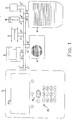
- an antitheft plant of this invention includes a central control unit 1 having an alphanumeric keypad 11, for inputting instructions, and a display 12, and protection fittings such as a sensor 2, a magnetic contact 3, a connector 4, an actuator 5, an internal siren 6 and an external siren 7.
- Such protection fittings are connected with the central control unit by means of a two-wire line, including two transmission lines 1', 1", respectively of output from, and return or response to the central control unit 1.
- the protection fittings are connected onto such two-wire line in parallel, through respective connection branches 2', 2"; 3', 3"; 4', 4"; 5', 5"; 6', 6"; 7', 7".
- FIGURE 2 the circuit constitution is depicted of an embodiment of this invention, based whereupon one is able to understand the operating stages of the installation of the antitheft plant of this invention.
- the central control unit 1 includes a central control unit board 13, the main component whereof is a central control unit microprocessor or CPU (Central Processing Unit) 21.
- the latter communicates, through an address bus 101 and through a data bus 102, an output and an input bus from/into it respectively, with an EPROM 22, an E 2 PROM 23, a RAM memory 24, and circuits for selecting memories and input/output devices 25.
- the central control unit microprocessor 21 also communicates with alphanumeric keypad 11, through a keypad interface 26 and a keypad connector 27, as well as with display 12 through a display output 28 and a display connector 29.
- the central control unit board 13 also includes a Universal Asynchronous Receiver-Transmitter or UART 30, which communicates as a transmitter TX and as a receiver RX through a UART connection board 30' and that receives a signal from a frequency divider circuit 30"; a serial port 31 having a serial port connection board 31'; a date and hour timer 32, and a socket for telephone sequence switch 33, all communicating on data bus 102.
- Microprocessor 21 controls the mentioned units through bidirectional control lines 103.
- a clock circuit 34 sends a clock signal to central control unit microprocessor 21 and to frequency divider 30".
- a reset circuit 35 sends a signal to central control unit microprocessor 21 and to UART 30.
- Central control unit board transmits and receives codes through transmission line 1' and reception line 1" respectively, to/from each protection fitting interface module 14.
- the latter includes a protection fitting microprocessor or CPU 36 with a clock circuit 37 and a reset circuit 38.
- Protection fitting interface module includes a protection fitting E 2 PROM memory 39 which an address bus 105 accesses from protection fitting microprocessor 36.
- a data bus 106 and a group of control lines 107 connect protection fitting E 2 PROM memory 39 and protection fitting microprocessor 36.
- the codes sent by/coming to the central control unit enter into/go out of protection fitting interface module 14 through a connection board 40 by means of a first and a second amplifier 41, 42.
- the circuit also includes a sensor or connector input interface 15 and a siren or actuator output interface 16.
- An output signal line 43' and an antitamper signal line 43" go out of a sensor or connector 43.
- Such lines form inputs to logical gates AND or of logical product 44, 45, whereinto lines 44', 45' respectively come from data bus 106, and wherefrom output lines 44", 45" respectively go out, to data bus 106.
- a siren or actuator 46 has, as its input, an actuation line 108 from control lines 107, an output line 46' and an antitamper signal line 46".
- the latter two outputs form inputs to gates AND 47, 48, which have, as their second inputs, a response signal line 111, and a line 112 respectively, and, as their outputs, lines 47', 48' that add themselves to lines 44", 45".
- EPROM memory 22 a programme which checks the correcteness of the operation of the antitheft plant or system, and first of all displays on display 12 information for presenting the antitheft plant, such as for instance "WELCOME IN THE SYSTEM". Thereafter a main menu page is displayed, such as for instance:
- the installer finds himself in a condition to have to carry out a first selection. Supposing the selected item to be "First programming", the system asks for introducing, through fingering on keypad 11, an antitamper safety code, for the protection of the subsequent programming stage.
- the identification codes so can be provided in a numeric succession by pressing ENTER key 11 1 .
- the numbering limit of protection fittings can depend both on memory size and on the number of protection fittings that can be connected, without overcoming absorption limits. Moreover, the numbering can be subdivided in groups of protection fittings based on categories of protection fittings. For instance, the sensors can be made to fall between 2000 and 2999, actuators between 3000 and 3999, so as to partition E 2 PROM memory in a plurality of indexed blocks. Simultaneously with this operation central control unit microprocessor 21 transmits through UART transceiver 30, a check code equivalent to ZERO, which is received from protection fitting interface module 14.
- Protection fitting microprocessor 36 thereof fetches the check code on a line of data bus 106, converting it from serial to parallel through internal registers thereof. Then it compares it with a code present in protection fitting E 2 PROM memory 39. If the code corresponds to the one present in the memory, then protection fitting microprocessor 36 fetches, from the same memory, a further code, the the serial number, which is stored in the manufacturing stage, and transmits it to the central control unit through return line 1".
- UART transceiver 30 converts information from serial to parallel and puts it at the disposal of central control unit microprocessor 21. Through this code the circuit sets the category of devices whereto the protection fitting belongs, displaying its name on display 12, as mentioned above.
- the cursor appears, for instance in a lightening or a pulsed form, which invites the installer to introduce the following of the description through alphanumeric keypad 11.
- the protection device or fitting is identified and stored in the memory area marked by the code itself, at the same time the code is transferred to the connected protection fitting to be stored in protection fitting E 2 PROM 39.
- each protection fitting which will have to be connected to the central processing unit, such as for instance sensors, connectors, magnetic contacts, detectors, actuators, sirens.
- central control unit 1 At the end of the programming the electric power supply is cut out to central control unit 1 and one proceeds to a connection in parallel of all protection fittings on two-wire line 1', 1", respecting the spaces assigned in the stage of the description. After the installation power is again given to the central control unit 1.
- Display 12 displays a welcome introduction, e.g. "WELCOME IN THE SYSTEM", and immediately after the circuit starts scanning all protection fittings present on two-wire line 1', 1", going to check their state one at a time.
- Central control unit 21 fetches from E 2 PROM 23 the codes assigned in the programming stage and inputs them onto transmission line 1', one at a time.
- Each code is simultaneously fetched by all protection fittings or devices present on two-wire line 1', 1" and stored in the internal registers of each protection fitting microprocessor 36. At this point the code present in protection fitting E 2 PROM 39 is fetched and compared with the one just stored in the registers in the protection fitting microprocessor. If the two codes are equal, the protection fitting whereto it relates sends a state response to the central control unit; if the two codes are not equal, it sets its output to a high-impedence state till when it will receive the corresponding code. The response to be sent to the central control unit 1 is still fetched by protection fitting microprocessor 36 and finds itself on output lines 44', 45' of detector input interface.
- the senor shows itself with two logical levels: in case of alarm it presents the output signal at a HIGH level, otherwise at a LOW level, the same thing happens for the antitamper set by signal TAMPER.
- the antitamper function is realized by means of a button which in a normal position is kept pressed by a lever. In this position the output signal is an enable logical level. If one tries to open the box that holds the circuits, the lever lifts up and the output signal changes state, turning the alarm on. After putting under test lines 44', 45', the same protection fitting microprocessor 36 takes a binary information therefrom, that it sends to central control unit 1 in a serial format.
- central control unit 21 fetches this information and through a programme it presents on display 12, with a message, the behaviour of polled protection fitting. Immediately after, microprocessor 21 increments a code counter by a unity, and repeats such procedure indefinitely, till when the electric power supply is cut out.
- the preceding stage is a passive operation, in that the central control unit goes to poll the detector or sensor to decide how to behave in the following. Now the action is opposite, in that the central control unit, if is acknowledges an alarm, has to instruct the actuators to turn themselves on.
- Central control unit microprocessor 21 fetches the codes corresponding to actuators from E 2 PROM 23 and transmits them on transmission line 1'. The code are received by all actuators and then compared with their respective internal codes. At this point the microprocessor of the actuator which the code corresponds to, goes to enable the actuator through actuation line 108. Immediately after output interface 16 provides a response of confirmed actuation 47', that microprocessor 36 trasmits to the central control unit. Through such a response the central control unit ensures itself that the actuators are actually turned on, so avoiding the problem of errors that could arise during the transmission of data. Display 12 indicates with a message all protection fittings turned on.
- the central alarm unit is equipped with a modem, wherethrough being able to put itself in communication with a server for the connection to Internet network and to the electronic mail services to control and monitor the antitheft plant by computer.
- the central alarm unit is equipped with a modem (not shown) for a communication with an Internet/electronic mail server, the functional insertion whereof will fall within the designing skill of the average man of the art, whereby a description thereof is omitted herein.
- a cellular phone emits, through its antenna 200', a short-text-message signal S1 to a radio link 202, which returns it as a signal S3 to transceiver 203, which receives it through an antenna 203'.
- Transceiver 203 allows central alarm unit 1 to be controlled and monitored through SMSs. Indeed, the data processed by the latter arrive at transceiver 203 through a connector 203", wherein they are encrypted and sent, upon composing a user code, to radio link 202 through antenna 203'.
- Antitheft plant information is so transmitted to the cellular phone besides precedently programmed information, in the progress of the installation. If one has the need of instructing a device connected to the central alarm unit it will suffice to compose a message that indicates the operations to be performed and to send it to transceiver 203 by network.
- the central alarm unit and a cellular phone are endowed with respective transceivers 204 (having a connector 204'), 204" tuned with each other.
- the cellular phone is endowed with a field sensor.
- a field indicator C is made to appear, which indicates a signal strength based on a number of marks turned on; if at least one of the latter is on, one can communicate with the central alarm unit in cordless mode and then have a direct dialogue with it through signal S2, as represented in FIGURE 4.
- the cellular phone is endowed with other two keys 206, 207, which can be used to visualize on display 205 the receiving-transmitting mode one wants to use, i.e., for instance, with kay 206 one can visualize 'cordless' mode and with key 207 'network' mode.
- a key can be used to select the modes sequentially, and the other key can be used for directly controlling an actuator, for instance an automatic gate. For the latter mode the user will be able to input a routine, selecting at his/her will how to exploit the control, programming it through the same code present in the actuator connected to the central alarm unit.
- the cellular phone includes an antenna 200', a transceiver 203"', an additional, inventive transceiver 204"', a control circuit 208 and a selection circuit 209.
- the selection circuit 209 has as its input a bidirectional line for a cellular mobile phone signal SG from transceiver 203"' and a bidirectional line for a cordless communication signal SC.
- Control circuit 208 includes the microprocessor central control unit of the cellular phone with memories, keypad control and data visualization on the display, and has as its input, from the selection circuit, a line for a call warning signal LC, a bidirectional line for an output or utility signal SU and, as its output to the selection circuit, a line for a selection signal LS.
- control circuit 208 enables the line for selection signal LS, letting cordless communication field signal SC, coming from transceiver 204"', through the line for utility signal SU.
- Control circuit 208 represents a multiplexer which, based on the state of the signal on the line for selection signal SL enables/inhibits the channel preselected by the keypad.
- transceiver 204"' through the phone signal line (e.g. GSM signal) SG enables a trigger circuit in selection circuit 209 activating call warning line LC.
- Control circuit 208 fetches this piece of information and besides making rings to be emitted, makes a signalizer I on the display to wink (see FIGURE 3). In the meanwhile one has all the time necessary for terminating the operation of managing the central alarm unit, avoiding a loss of useful information. Then, by pressing the key of phone network mode, we can visualize the number of the calling user and then answer.
- signal S1 is picked up by the antenna of the cellular phone and received by transceiver 203"'.
- phone signal line SG information passes by virtue of the logical state of selection signal line SL which selects selection circuit 209 on such a signal while SC is locked.
- the output signal or useful signal SU communicates with the microprocessor present in control circuit 208. Starting from such a moment if someone telephones, the cellular phone behaves normally and then one can directly answer, as in the customary way.
- a signal S2 should arrive at the cellular phone, including alarm state information, on display 205 indicator I and the loudspeaker will emit acoustic pulses as when text messages are received.
- the selection circuit will let signal SG and signal SG to pass one at a time, alternately, in the form of pulse trains.
- the transceiver of the central alarm unit is further endowed with an input 210, having the function of interfacing with a fixed phone line, so featuring a proper cordless phone.
- the functions are the same as a cordless phone already on the market, additionally, however, the cordless phone will be able to interact with the central control unit too.
Landscapes
- Physics & Mathematics (AREA)
- General Physics & Mathematics (AREA)
- Engineering & Computer Science (AREA)
- Business, Economics & Management (AREA)
- Emergency Management (AREA)
- Computer Security & Cryptography (AREA)
- Multimedia (AREA)
- Human Computer Interaction (AREA)
- Alarm Systems (AREA)
Priority Applications (1)
| Application Number | Priority Date | Filing Date | Title |
|---|---|---|---|
| EP02425060A EP1335337A1 (fr) | 2002-02-07 | 2002-02-07 | Système antivol commandé et programmé par ordinateur ou par téléphone, avec identification de l'état de chaque module de protection |
Applications Claiming Priority (1)
| Application Number | Priority Date | Filing Date | Title |
|---|---|---|---|
| EP02425060A EP1335337A1 (fr) | 2002-02-07 | 2002-02-07 | Système antivol commandé et programmé par ordinateur ou par téléphone, avec identification de l'état de chaque module de protection |
Publications (1)
| Publication Number | Publication Date |
|---|---|
| EP1335337A1 true EP1335337A1 (fr) | 2003-08-13 |
Family
ID=27589207
Family Applications (1)
| Application Number | Title | Priority Date | Filing Date |
|---|---|---|---|
| EP02425060A Ceased EP1335337A1 (fr) | 2002-02-07 | 2002-02-07 | Système antivol commandé et programmé par ordinateur ou par téléphone, avec identification de l'état de chaque module de protection |
Country Status (1)
| Country | Link |
|---|---|
| EP (1) | EP1335337A1 (fr) |
Cited By (2)
| Publication number | Priority date | Publication date | Assignee | Title |
|---|---|---|---|---|
| EP1643470A3 (fr) * | 2004-10-04 | 2006-08-02 | Honeywell International Inc. | Mèthode de programmation d'un panneau de commande d'un système de sécurité pour sa compatibilité avec un dispositif d'ouverture de porte |
| WO2009060204A1 (fr) * | 2007-11-09 | 2009-05-14 | Mobile Alarm Sensors Ltd | Dispositif d'alarme anti-intrusion |
Citations (6)
| Publication number | Priority date | Publication date | Assignee | Title |
|---|---|---|---|---|
| EP0178474A2 (fr) * | 1984-09-20 | 1986-04-23 | Siemens Aktiengesellschaft | Procédé et dispositif pour l'identification du détecteur d'un système détecteur de dangers |
| GB2335523A (en) * | 1998-03-17 | 1999-09-22 | Ascot Management Solutions Ltd | Remote monitoring system using the GSM network |
| JP2000036088A (ja) * | 1996-02-24 | 2000-02-02 | Masanobu Kujirada | 携帯型セキュリティシステム |
| US6198389B1 (en) * | 1999-06-22 | 2001-03-06 | Napco Security Systems, Inc. | Integrated individual sensor control in a security system |
| DE19940700A1 (de) * | 1999-08-27 | 2001-03-08 | Job Lizenz Gmbh & Co Kg | Verfahren und Vorrichtung zur automatischen Zuweisung von Melderadressen bei einer Gefahrenmeldeanlage |
| WO2001037589A1 (fr) * | 1999-11-19 | 2001-05-25 | Triguard Group Llc | Systeme d'alarme sans fil et telephone combines relies a un reseau de gestion de l'information permettant l'emission automatique d'alertes et d'autres informations |
-
2002
- 2002-02-07 EP EP02425060A patent/EP1335337A1/fr not_active Ceased
Patent Citations (6)
| Publication number | Priority date | Publication date | Assignee | Title |
|---|---|---|---|---|
| EP0178474A2 (fr) * | 1984-09-20 | 1986-04-23 | Siemens Aktiengesellschaft | Procédé et dispositif pour l'identification du détecteur d'un système détecteur de dangers |
| JP2000036088A (ja) * | 1996-02-24 | 2000-02-02 | Masanobu Kujirada | 携帯型セキュリティシステム |
| GB2335523A (en) * | 1998-03-17 | 1999-09-22 | Ascot Management Solutions Ltd | Remote monitoring system using the GSM network |
| US6198389B1 (en) * | 1999-06-22 | 2001-03-06 | Napco Security Systems, Inc. | Integrated individual sensor control in a security system |
| DE19940700A1 (de) * | 1999-08-27 | 2001-03-08 | Job Lizenz Gmbh & Co Kg | Verfahren und Vorrichtung zur automatischen Zuweisung von Melderadressen bei einer Gefahrenmeldeanlage |
| WO2001037589A1 (fr) * | 1999-11-19 | 2001-05-25 | Triguard Group Llc | Systeme d'alarme sans fil et telephone combines relies a un reseau de gestion de l'information permettant l'emission automatique d'alertes et d'autres informations |
Non-Patent Citations (1)
| Title |
|---|
| PATENT ABSTRACTS OF JAPAN vol. 2000, no. 05 14 September 2000 (2000-09-14) * |
Cited By (2)
| Publication number | Priority date | Publication date | Assignee | Title |
|---|---|---|---|---|
| EP1643470A3 (fr) * | 2004-10-04 | 2006-08-02 | Honeywell International Inc. | Mèthode de programmation d'un panneau de commande d'un système de sécurité pour sa compatibilité avec un dispositif d'ouverture de porte |
| WO2009060204A1 (fr) * | 2007-11-09 | 2009-05-14 | Mobile Alarm Sensors Ltd | Dispositif d'alarme anti-intrusion |
Similar Documents
| Publication | Publication Date | Title |
|---|---|---|
| US5598456A (en) | Integrated telephone, intercom, security and control system for a multi-unit building | |
| DE60014642T2 (de) | Programierbares alarmsystem | |
| KR20100124730A (ko) | 경보기 및 경보기 시스템 | |
| JP4740232B2 (ja) | サーキット・ブレーカのための電子的保護デバイス及び対応するプログラミング方法 | |
| US6331816B1 (en) | Automatic control system for security apparatus based on the presence of a user | |
| WO2004079684A1 (fr) | Systeme de securite | |
| US7096001B2 (en) | Security system with telephone controller | |
| US20090128321A1 (en) | Home appliance with security function | |
| RU72778U1 (ru) | Устройство мобильной сигнализации | |
| JP4514404B2 (ja) | セキュリティ自動切替システム | |
| EP1335337A1 (fr) | Système antivol commandé et programmé par ordinateur ou par téléphone, avec identification de l'état de chaque module de protection | |
| JP2007058663A (ja) | インターホンシステム | |
| KR100793813B1 (ko) | 인터넷망과 공중망 및 무선망을 이용한 원격 제어 보안시스템 및 그 제어방법 | |
| US20070270176A1 (en) | Communications device | |
| JPH054363Y2 (fr) | ||
| EP1582048A2 (fr) | Module de passerelle universelle permettant d'etablir une interface entre une commande de systeme de securite et des dispositifs peripheriques | |
| JP2001127897A (ja) | 携帯電話ホームコントロールシステム | |
| JP2006101328A (ja) | 集合住宅インターホンシステム | |
| US20070046780A1 (en) | Remote intercom operator with finder | |
| JP3846396B2 (ja) | インターホンシステム | |
| KR200165407Y1 (ko) | 원격제어 및 원격감시 기능을 포함하는 전자키 제어장치 | |
| JP2501332B2 (ja) | 集合住宅用監視システム | |
| KR200215205Y1 (ko) | 다이얼펄스를 이용한 유무선 종합경보장치 | |
| JP2009260827A (ja) | 操作表示装置 | |
| JP2010200094A (ja) | インターホン装置 |
Legal Events
| Date | Code | Title | Description |
|---|---|---|---|
| PUAI | Public reference made under article 153(3) epc to a published international application that has entered the european phase |
Free format text: ORIGINAL CODE: 0009012 |
|
| AK | Designated contracting states |
Designated state(s): AT BE CH CY DE DK ES FI FR GB GR IE IT LI LU MC NL PT SE TR |
|
| AX | Request for extension of the european patent |
Extension state: AL LT LV MK RO SI |
|
| AKX | Designation fees paid | ||
| 17P | Request for examination filed |
Effective date: 20040308 |
|
| RBV | Designated contracting states (corrected) |
Designated state(s): AT BE CH CY DE LI |
|
| REG | Reference to a national code |
Ref country code: DE Ref legal event code: 8566 |
|
| RBV | Designated contracting states (corrected) |
Designated state(s): AT BE CH CY DE DK ES FI FR GB GR IE IT LI LU MC NL PT SE TR |
|
| D17P | Request for examination filed (deleted) | ||
| 17Q | First examination report despatched |
Effective date: 20040923 |
|
| R17P | Request for examination filed (corrected) |
Effective date: 20040308 |
|
| STAA | Information on the status of an ep patent application or granted ep patent |
Free format text: STATUS: THE APPLICATION HAS BEEN REFUSED |
|
| 18R | Application refused |
Effective date: 20061130 |