EP1335407A2 - Elektrodenloses Beleuchtungssystem und Kolben dafür - Google Patents
Elektrodenloses Beleuchtungssystem und Kolben dafür Download PDFInfo
- Publication number
- EP1335407A2 EP1335407A2 EP02016179A EP02016179A EP1335407A2 EP 1335407 A2 EP1335407 A2 EP 1335407A2 EP 02016179 A EP02016179 A EP 02016179A EP 02016179 A EP02016179 A EP 02016179A EP 1335407 A2 EP1335407 A2 EP 1335407A2
- Authority
- EP
- European Patent Office
- Prior art keywords
- bulb
- microwave
- conductive
- electric field
- lighting
- Prior art date
- Legal status (The legal status is an assumption and is not a legal conclusion. Google has not performed a legal analysis and makes no representation as to the accuracy of the status listed.)
- Granted
Links
- 230000005684 electric field Effects 0.000 claims abstract description 22
- 230000001737 promoting effect Effects 0.000 claims abstract description 9
- 239000000463 material Substances 0.000 claims description 12
- 239000004020 conductor Substances 0.000 claims description 5
- VYPSYNLAJGMNEJ-UHFFFAOYSA-N Silicium dioxide Chemical compound O=[Si]=O VYPSYNLAJGMNEJ-UHFFFAOYSA-N 0.000 claims description 4
- 239000000919 ceramic Substances 0.000 claims description 4
- 238000006243 chemical reaction Methods 0.000 claims description 4
- 239000012141 concentrate Substances 0.000 claims description 4
- 239000005350 fused silica glass Substances 0.000 claims description 4
- 239000011248 coating agent Substances 0.000 claims description 3
- 238000000576 coating method Methods 0.000 claims description 3
- 230000015556 catabolic process Effects 0.000 claims description 2
- 238000006731 degradation reaction Methods 0.000 claims description 2
- XKRFYHLGVUSROY-UHFFFAOYSA-N Argon Chemical compound [Ar] XKRFYHLGVUSROY-UHFFFAOYSA-N 0.000 description 6
- 239000011261 inert gas Substances 0.000 description 6
- 238000001816 cooling Methods 0.000 description 5
- 238000007599 discharging Methods 0.000 description 5
- 239000011669 selenium Substances 0.000 description 4
- 229910052724 xenon Inorganic materials 0.000 description 4
- FHNFHKCVQCLJFQ-UHFFFAOYSA-N xenon atom Chemical compound [Xe] FHNFHKCVQCLJFQ-UHFFFAOYSA-N 0.000 description 4
- 229910052786 argon Inorganic materials 0.000 description 3
- 239000007789 gas Substances 0.000 description 3
- BUGBHKTXTAQXES-UHFFFAOYSA-N Selenium Chemical compound [Se] BUGBHKTXTAQXES-UHFFFAOYSA-N 0.000 description 2
- NINIDFKCEFEMDL-UHFFFAOYSA-N Sulfur Chemical compound [S] NINIDFKCEFEMDL-UHFFFAOYSA-N 0.000 description 2
- 239000000654 additive Substances 0.000 description 2
- -1 and the like Substances 0.000 description 2
- 238000007664 blowing Methods 0.000 description 2
- 238000007796 conventional method Methods 0.000 description 2
- 230000000694 effects Effects 0.000 description 2
- 150000002366 halogen compounds Chemical class 0.000 description 2
- 229910052711 selenium Inorganic materials 0.000 description 2
- 238000001228 spectrum Methods 0.000 description 2
- 229910052717 sulfur Inorganic materials 0.000 description 2
- 239000011593 sulfur Substances 0.000 description 2
- 239000007769 metal material Substances 0.000 description 1
- 238000012986 modification Methods 0.000 description 1
- 230000004048 modification Effects 0.000 description 1
- 230000007935 neutral effect Effects 0.000 description 1
Images

Classifications
-
- H—ELECTRICITY
- H01—ELECTRIC ELEMENTS
- H01J—ELECTRIC DISCHARGE TUBES OR DISCHARGE LAMPS
- H01J65/00—Lamps without any electrode inside the vessel; Lamps with at least one main electrode outside the vessel
- H01J65/04—Lamps in which a gas filling is excited to luminesce by an external electromagnetic field or by external corpuscular radiation, e.g. for indicating plasma display panels
-
- H—ELECTRICITY
- H05—ELECTRIC TECHNIQUES NOT OTHERWISE PROVIDED FOR
- H05B—ELECTRIC HEATING; ELECTRIC LIGHT SOURCES NOT OTHERWISE PROVIDED FOR; CIRCUIT ARRANGEMENTS FOR ELECTRIC LIGHT SOURCES, IN GENERAL
- H05B41/00—Circuit arrangements or apparatus for igniting or operating discharge lamps
- H05B41/14—Circuit arrangements
- H05B41/24—Circuit arrangements in which the lamp is fed by high frequency AC, or with separate oscillator frequency
-
- H—ELECTRICITY
- H01—ELECTRIC ELEMENTS
- H01J—ELECTRIC DISCHARGE TUBES OR DISCHARGE LAMPS
- H01J65/00—Lamps without any electrode inside the vessel; Lamps with at least one main electrode outside the vessel
- H01J65/04—Lamps in which a gas filling is excited to luminesce by an external electromagnetic field or by external corpuscular radiation, e.g. for indicating plasma display panels
- H01J65/042—Lamps in which a gas filling is excited to luminesce by an external electromagnetic field or by external corpuscular radiation, e.g. for indicating plasma display panels by an external electromagnetic field
- H01J65/044—Lamps in which a gas filling is excited to luminesce by an external electromagnetic field or by external corpuscular radiation, e.g. for indicating plasma display panels by an external electromagnetic field the field being produced by a separate microwave unit
Definitions
- the present invention relates to an electrodeless lighting system and a bulb therefor and particularly, to an electrodeless lighting system and a bulb therefor, capable of emitting light in case of re-lighting.
- an electrodeless lighting system is a device for emitting visible rays or ultraviolet rays by applying microwave to an electrodeless lamp, as a microwave generated in a magnetron is transmitted to a resonator though a waveguide and applied to an electrodeless bulb installed inside the resonator and filled material which is filled in the bulb is plasma polymerized. Therefore, the system has longer life span than that of incandescent lamp or fluorescent lamp which is generally used, and has higher lighting effect.
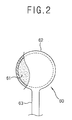
- Figure 1 is a longitudinal cross-sectional view showing a general electrodeless lighting system according to the conventional art and Figure 2 is a partial cut-away detailed view of a bulb in Figure 1.
- the conventional electrodeless lighting system includes a casing 10, a high voltage generator 20 positioned on the inner front surface of the casing 10 for generating high voltage, a magnetron 30 positioned at a predetermined interval from the high voltage generator 20, for generating microwave by the high voltage generated in the high voltage generator 20, a waveguide 40 fixed on the front surface of the casing 10 and protruded to the outside of the casing 10, for guiding the microwave generated from the magnetron 30, a resonator 50 installed at the front outer side of the casing 10 so that it is connected with the waveguide 40, for resonating the microwave guided through the waveguide 40 and at the same time, preventing leakage of microwave to the outside, a bulb 60 mounted to be capable of rotating inside the resonator 50, for generating light as the filled material is excited by the microwave, and a reflector 80 positioned at the circumference of the bulb 60, for reflecting light which is generated from the bulb 60 to the front.
- a fan housing 110 installed at the rear side of the casing 10 so that heat generated in the high voltage generator 20 and magnetron 30 is protected, for sucking external air, a cooling fan 100 positioned in the fan housing 110, for sucking external air and a fan motor 101 for rotating the cooling fan 100, are positioned inside the casing 10.
- the bulb 60 is positioned at the outer side of the exit 70 which is formed in the waveguide 40 and as shown in Figure 2, includes a bulb portion 62 which is formed in a globular shape having a filling space 61 therein, and a bulb stem 63 which is lengthened and formed in a rod shape having a predetermined length at a side of the bulb portion 62.
- the bulb stem 63 is connected to the rotation shaft 91 passing through the waveguide 40 with reference to Figure 1.
- the rotation shaft 91 is connected to a bulb motor 90 which is positioned between the fan housing 110 and the waveguide 40.
- the rotation shaft 91 is rotated by the operation of the bulb motor 90, the bulb is rotated by rotation of the rotation shaft 91. and accordingly, the bulb 60 is cooled.
- primary emission fills which lead light emission by forming plasma in the operation such as halogen compounds or sulfur (S), Selenium (Se), and the like, inert gas for forming plasma at the initial stage of light emission, such as argon (Ar), Xenon (Xe), Kripton (Kr) and the like and additives for easing lighting by helping initial discharge or adjusting a spectrum of the generated light, are filled in the bulb.
- plasma in the operation such as halogen compounds or sulfur (S), Selenium (Se), and the like
- inert gas for forming plasma at the initial stage of light emission such as argon (Ar), Xenon (Xe), Kripton (Kr) and the like and additives for easing lighting by helping initial discharge or adjusting a spectrum of the generated light, are filled in the bulb.
- a high voltage is generated in the high voltage generator 20 and a microwave is generated in the magnetron 30 by the high voltage impressed.
- the microwave generated in the magnetron 30 is transmitted to the resonator 50 through the waveguide 40 and a strong electric field is distributed in the resonator 50.
- the material which is filled inside the bulb 60 is discharged by the electric field and at the same time, evaporated, thus to generate plasma.
- the inert gas which is filled in the bulb 60 is discharged by a strong electric field distributed inside the resonator 50 and plasma is formed as the main luminous material is evaporated by heat which is generated by discharge of the inert gas. Then, light is emitted maintaining discharging by the microwave which is continuously supplied to the resonator 50.
- the bulb 60 is rotated by operating the bulb motor 90, the bulb 60 is cooled and an external air flows to the inside of the casing 10 as the cooling fan 100 is rotated by operating the fan motor 101, thus to cooling the high voltage generator 20 and magnetron 30.
- the conventional electrodeless lighting system has a disadvantage that re-lighting is not directly conducted but in several tens of seconds or several minutes, if the bulb 60 is re-lit after light-out of the bulb 60 under the lighting condition.
- the disadvantage is caused since a sufficient mean free path of an electron having energy which is needed for plasma discharging can not be secured as the pressure of the neutral gas which is filled inside the bulb 60 is too high. Particularly, even though 5% of light efficiency is increased in case of using Xenon (Xe) as the inertia gas than in case of using just argon (Ar), discharging becomes more difficult under the condition of high voltage because of the large collision cross section of Xenon (Xe).
- the internal pressure of the bulb 60 can be lowered by cooling by directly blowing a strong wind.
- the conventional method caused problems of an increase in the cost for mounting an additional device for blowing the strong wind, reliability of the additional device, utilization of the circumference of the electrodeless lighting system, and light shading which is discharged by the additional devices.
- an object of the present invention is to provide an electrodeless lighting system, capable of minimizing the time required for lighting of a bulb.
- an electrodeless lighting system including a waveguide having an outlet which is installed being protruded from the inside of a casing to the outside of the casing, for transmitting a microwave generated in the magnetron, a resonator fixed at the outer side of the outlet of the waveguide, for forming a resonant region in which the microwave is resonated, a bulb for generating light as plasma is generated by an electric field which is formed inside the resonator and a lighting promoting means positioned inside the bulb, for concentrating the electric field so that light is rapidly emitted when the microwave is applied.
- the conductive member includes a basic member having a predetermined diameter and length to maintain a physical shape and a conductive layer made by coating a conductive material on the basic member, for concentrating the electric field.
- the conductive member of the electrodeless lighting system in accordance with the present invention further includes a protection layer for preventing the conductive member from having a reaction directly with plasma on the conductive layer.
- the electrodeless lighting system in accordance with the present invention convenience of a user can be achieved and reliability of lighting can be increased, since electric field is concentrated at both ends of the conductive member which is mounted inside the bulb in case of applying a microwave of the bulb by positioning the conductive member in the filling space of the bulb and the bulb can emit light.
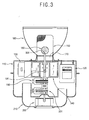
- Figure 3 is a cross-sectional view showing an electrodeless lighting system in accordance with the present invention
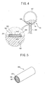
- Figure 4 is a cross-sectional view showing a bulb and conductive member of the electrodeless lighting system in accordance with an embodiment of the present invention
- Figure 5 is a partially cut perspective view showing the conductive member taken along section line V-V of Figure 4.
- the conventional electrodeless lighting system includes a casing 110 of a predetermined shape, a high voltage generator 120 positioned on the inner front surface of the casing 110 for generating high voltage, a magnetron 130 positioned at a predetermined interval from the high voltage generator 120, for generating microwave by the high voltage generated in the high voltage generator 120, a waveguide 140 for guiding the microwave generated from the magnetron 130, a resonator 150 installed at the front outer side of the casing so that it is connected with the waveguide 140, for resonating the microwave guided through the waveguide 140 and at the same time, preventing leakage of the microwave to the outside, a bulb 160 mounted to be capable of rotating inside the resonator 150, for generating light as the filled material is excited by the microwave, and a reflector 180 positioned at the circumference of the bulb 160, for reflecting light which is generated from the bulb 160 to the front.
- the resonator 150 is formed in a cylindrical shape having a side closed, as a mesh type to intercept leakage of the microwave and pass light generated in the bulb 160.
- the bulb 160 is positioned at the outer side of the exit 170 which is formed in the waveguide 140 and as shown in Figure 4, includes a bulb portion 162 which is formed in a globular shape having a filling space 161 therein, and a bulb stem 163 which is lengthened and formed in a rod shape having a predetermined length at a side of the bulb portion 162.
- the bulb stem 163 is connected to the rotation shaft 191 passing through the waveguide 140.
- the rotation shaft 191 is connected to a bulb motor 190 which is positioned between the fan housing 210 and the waveguide 140.
- the rotation shaft 191 is rotated by the operation of the bulb motor 190, the bulb 160 is rotated by rotation of the rotation shaft 191 and accordingly, the bulb 160 is cooled.
- primary emission fills which lead light emission by forming plasma in the operation such as halogen compounds or sulfur (S), Selenium (Se), and the like, inert gas for forming plasma at the initial stage of light emission, such as argon (Ar), Xenon (Xe), Kripton (Kr) and the like and additives for easing lighting by helping initial discharge or adjusting a spectrum of the generated light, are filled in the bulb.
- inert gas for forming plasma at the initial stage of light emission such as argon (Ar), Xenon (Xe), Kripton (Kr) and the like and additives for easing lighting by helping initial discharge or adjusting a spectrum of the generated light, are filled in the bulb.
- a conductive member 300 having conductivity to concentrate an electric field generated when the microwave is applied, is positioned in the filling space 161 of the bulb 160.
- the conductive member 300 includes a basic member 301 having a predetermined diameter and length to maintain a physical shape and a conductive layer 302 which is coated on the basic member 301 and made of a conductive material to induce concentration of electric field.
- a protection layer 303 for preventing degradation by a reaction with plasma is formed on the conductive layer 302 coated on the basic member 301.
- the basic member 301 is made of SiC which is not deformed at high temperature higher than several hundreds of degrees.
- the conductive layer 302 is made of a metallic material and preferably, made of Pt.
- the protection layer 303 is made of materials having thermostability, such as ceramic or fused silica.
- the conductive member 300 is formed in a wire type having a diameter of 5 ⁇ m and efficiency becomes excellent as the length of the conductive layer 302 is longer than the diameter with the length of the conductive layer 302 of 0.5 ⁇ m or shorter. It is desirable that the ratio between the diameter and length is formed smaller than 1/100.
- a high voltage is generated in the high voltage generator 120 and a microwave is generated in the magnetron 130 by the high voltage generated in the high voltage generator 120.
- the microwave generated in the magnetron 130 is transmitted to the resonator 150 through the waveguide 140 and a strong electric field is distributed in the resonator 150.
- the material which is filled in the filling space 161 of the bulb 160 is discharged by the electric field and at the same time, evaporated, thus to generate plasma.
- the inert gas which is filled in the bulb 160 is discharged by a strong electric field distributed inside the resonator 150 and plasma is formed as the main luminous material is evaporated by heat which is generated by discharge of the inert gas. Then, light is emitted maintaining discharging by the microwave which is continuously supplied to the resonator 150.
- lighting characteristic can be easily improved since a conductive member 300 is inserted inside the filling space of the bulb 160.
- the electric field is concentrated at both ends of the conductive member mounted in the bulb and accordingly, the bulb rapidly emits light in case of applying the microwave to the bulb, by positioning a conductive member in the filling space of the bulb, thus to achieve convenience of the user and increase reliability of lighting.
Landscapes
- Physics & Mathematics (AREA)
- Engineering & Computer Science (AREA)
- Plasma & Fusion (AREA)
- Electromagnetism (AREA)
- Non-Portable Lighting Devices Or Systems Thereof (AREA)
- Discharge Lamps And Accessories Thereof (AREA)
Applications Claiming Priority (2)
| Application Number | Priority Date | Filing Date | Title |
|---|---|---|---|
| KR10-2002-0002807A KR100442397B1 (ko) | 2002-01-17 | 2002-01-17 | 무전극 조명기기의 점등 촉진구조 |
| KR2002002807 | 2002-01-17 |
Publications (3)
| Publication Number | Publication Date |
|---|---|
| EP1335407A2 true EP1335407A2 (de) | 2003-08-13 |
| EP1335407A3 EP1335407A3 (de) | 2004-10-13 |
| EP1335407B1 EP1335407B1 (de) | 2010-11-24 |
Family
ID=19718562
Family Applications (1)
| Application Number | Title | Priority Date | Filing Date |
|---|---|---|---|
| EP02016179A Expired - Lifetime EP1335407B1 (de) | 2002-01-17 | 2002-07-20 | Elektrodenloses Beleuchtungssystem und Kolben dafür |
Country Status (6)
| Country | Link |
|---|---|
| US (1) | US6744221B2 (de) |
| EP (1) | EP1335407B1 (de) |
| JP (1) | JP2003217522A (de) |
| KR (1) | KR100442397B1 (de) |
| CN (1) | CN1433047A (de) |
| DE (1) | DE60238381D1 (de) |
Cited By (2)
| Publication number | Priority date | Publication date | Assignee | Title |
|---|---|---|---|---|
| EP1519408A3 (de) * | 2003-09-03 | 2006-03-08 | Lg Electronics Inc. | Elektrodenloses Beleuchtungssystem |
| EP1519405A3 (de) * | 2003-09-03 | 2006-05-10 | LG Electronics Inc. | Elektrodenloses Beleuchtungssystem |
Families Citing this family (7)
| Publication number | Priority date | Publication date | Assignee | Title |
|---|---|---|---|---|
| KR100556782B1 (ko) * | 2003-12-06 | 2006-03-10 | 엘지전자 주식회사 | 플라즈마 램프 시스템 |
| JP4411975B2 (ja) * | 2004-01-09 | 2010-02-10 | 横浜ゴム株式会社 | 空気入りタイヤ及びタイヤ金型 |
| KR20060036839A (ko) * | 2004-10-26 | 2006-05-02 | 엘지전자 주식회사 | 플라즈마를 이용한 무전극 조명기기의 전구 구조 및 그제조방법 |
| KR20060036809A (ko) * | 2004-10-26 | 2006-05-02 | 엘지전자 주식회사 | 플라즈마를 이용한 무전극 조명기기의 전구구조 |
| JP2006294277A (ja) * | 2005-04-06 | 2006-10-26 | Koito Mfg Co Ltd | 無電極放電灯及び無電極放電灯装置 |
| KR20150084406A (ko) * | 2014-01-14 | 2015-07-22 | 엘지전자 주식회사 | 무전극 조명장치 |
| KR20150089183A (ko) * | 2014-01-27 | 2015-08-05 | 엘지전자 주식회사 | 무전극 조명장치 |
Family Cites Families (9)
| Publication number | Priority date | Publication date | Assignee | Title |
|---|---|---|---|---|
| JPS56126250A (en) * | 1980-03-10 | 1981-10-03 | Mitsubishi Electric Corp | Light source device of micro wave discharge |
| JPS57202644A (en) * | 1981-06-09 | 1982-12-11 | Mitsubishi Electric Corp | No-electrode discharge lamp |
| NL8400409A (nl) * | 1984-02-09 | 1985-09-02 | Philips Nv | Elektrodeloze lagedrukgasontladingslamp. |
| NL8500736A (nl) * | 1985-03-14 | 1986-10-01 | Philips Nv | Elektrodeloze lagedrukontladingslamp. |
| US5847517A (en) * | 1996-07-10 | 1998-12-08 | Fusion Lighting, Inc. | Method and apparatus for igniting electrodeless lamp with ferroelectric emission |
| JP3620371B2 (ja) * | 1999-10-01 | 2005-02-16 | ウシオ電機株式会社 | 高周波励起点光源ランプ装置 |
| AU2001255308A1 (en) * | 2000-04-26 | 2001-11-07 | Cornell Research Foundation Inc. | Lamp utilizing fiber for enhanced starting field |
| KR100396772B1 (ko) * | 2001-02-02 | 2003-09-03 | 엘지전자 주식회사 | 마이크로파를 이용한 조명기구 |
| EP1335408B1 (de) * | 2002-01-25 | 2007-11-07 | Lg Electronics Inc. | Elektrodenloses Beleuchtungssystem |
-
2002
- 2002-01-17 KR KR10-2002-0002807A patent/KR100442397B1/ko not_active Expired - Fee Related
- 2002-07-20 DE DE60238381T patent/DE60238381D1/de not_active Expired - Lifetime
- 2002-07-20 EP EP02016179A patent/EP1335407B1/de not_active Expired - Lifetime
- 2002-07-31 US US10/207,999 patent/US6744221B2/en not_active Expired - Fee Related
- 2002-08-02 CN CN02127413A patent/CN1433047A/zh active Pending
- 2002-08-22 JP JP2002241755A patent/JP2003217522A/ja active Pending
Cited By (2)
| Publication number | Priority date | Publication date | Assignee | Title |
|---|---|---|---|---|
| EP1519408A3 (de) * | 2003-09-03 | 2006-03-08 | Lg Electronics Inc. | Elektrodenloses Beleuchtungssystem |
| EP1519405A3 (de) * | 2003-09-03 | 2006-05-10 | LG Electronics Inc. | Elektrodenloses Beleuchtungssystem |
Also Published As
| Publication number | Publication date |
|---|---|
| CN1433047A (zh) | 2003-07-30 |
| EP1335407A3 (de) | 2004-10-13 |
| US6744221B2 (en) | 2004-06-01 |
| EP1335407B1 (de) | 2010-11-24 |
| DE60238381D1 (de) | 2011-01-05 |
| KR20030062558A (ko) | 2003-07-28 |
| JP2003217522A (ja) | 2003-07-31 |
| KR100442397B1 (ko) | 2004-07-30 |
| US20030132719A1 (en) | 2003-07-17 |
Similar Documents
| Publication | Publication Date | Title |
|---|---|---|
| JPH10321039A (ja) | マイクロ波放電ランプ装置 | |
| CN100349252C (zh) | 无电极照明系统 | |
| RU2232445C2 (ru) | Безэлектродная осветительная система | |
| US6744221B2 (en) | Electrodeless lighting system and bulb therefor | |
| JP2004207216A (ja) | 無電極照明器具の電球 | |
| US7397173B2 (en) | Lighting apparatus using microwave energy | |
| KR100498307B1 (ko) | 무전극 조명 시스템의 재발광 촉진 장치 | |
| US20100156295A1 (en) | Electrodeless bulb, and electrodeless lighting system having the same | |
| US6608443B1 (en) | Lighting apparatus using microwave energy | |
| KR100459448B1 (ko) | 무전극 조명기기의 무전극 전구 | |
| RU2226017C2 (ru) | Безэлектродная система освещения (варианты) | |
| JP3212291B2 (ja) | 無電極放電ランプ | |
| KR100451226B1 (ko) | 무전극 조명기기의 초기점등 촉진구조 | |
| KR100442398B1 (ko) | 무전극 조명기기의 재발광 촉진구조 | |
| JP4259274B2 (ja) | マイクロ波無電極放電灯装置 | |
| JP4225490B2 (ja) | 無電極照明機器 | |
| US7622856B2 (en) | Plasma lighting system having thin metallic film resonator | |
| JPH11102608A (ja) | 無電極放電ランプ装置 | |
| KR100396770B1 (ko) | 마그네트론 일체형 마이크로파 조명 장치 | |
| KR100533049B1 (ko) | 무전극 램프의 무전극 전구 | |
| KR100731156B1 (ko) | 제논 무전극 형광 램프의 전열구조 | |
| EP1414058A2 (de) | Elektrodenloses Lampensystem und zugehöriger Kolben | |
| JPH0869778A (ja) | 無電極放電ランプ |
Legal Events
| Date | Code | Title | Description |
|---|---|---|---|
| PUAI | Public reference made under article 153(3) epc to a published international application that has entered the european phase |
Free format text: ORIGINAL CODE: 0009012 |
|
| AK | Designated contracting states |
Designated state(s): AT BE BG CH CY CZ DE DK EE ES FI FR GB GR IE IT LI LU MC NL PT SE SK TR |
|
| AX | Request for extension of the european patent |
Extension state: AL LT LV MK RO SI |
|
| PUAL | Search report despatched |
Free format text: ORIGINAL CODE: 0009013 |
|
| AK | Designated contracting states |
Kind code of ref document: A3 Designated state(s): AT BE BG CH CY CZ DE DK EE ES FI FR GB GR IE IT LI LU MC NL PT SE SK TR |
|
| AX | Request for extension of the european patent |
Extension state: AL LT LV MK RO SI |
|
| 17P | Request for examination filed |
Effective date: 20050311 |
|
| 17Q | First examination report despatched |
Effective date: 20050425 |
|
| AKX | Designation fees paid |
Designated state(s): DE FR GB IT SE |
|
| GRAP | Despatch of communication of intention to grant a patent |
Free format text: ORIGINAL CODE: EPIDOSNIGR1 |
|
| RIN1 | Information on inventor provided before grant (corrected) |
Inventor name: PARK, BYEONG-JU Inventor name: LEE, JI-YOUNG Inventor name: KIM, HYUN-JUNG Inventor name: JEON, HYO-SIK Inventor name: JEON, YONG-SEOG Inventor name: CHOI, JOON-SIK |
|
| GRAS | Grant fee paid |
Free format text: ORIGINAL CODE: EPIDOSNIGR3 |
|
| GRAA | (expected) grant |
Free format text: ORIGINAL CODE: 0009210 |
|
| AK | Designated contracting states |
Kind code of ref document: B1 Designated state(s): DE FR GB IT SE |
|
| REG | Reference to a national code |
Ref country code: GB Ref legal event code: FG4D |
|
| REF | Corresponds to: |
Ref document number: 60238381 Country of ref document: DE Date of ref document: 20110105 Kind code of ref document: P |
|
| PG25 | Lapsed in a contracting state [announced via postgrant information from national office to epo] |
Ref country code: SE Free format text: LAPSE BECAUSE OF FAILURE TO SUBMIT A TRANSLATION OF THE DESCRIPTION OR TO PAY THE FEE WITHIN THE PRESCRIBED TIME-LIMIT Effective date: 20101124 |
|
| PLBE | No opposition filed within time limit |
Free format text: ORIGINAL CODE: 0009261 |
|
| STAA | Information on the status of an ep patent application or granted ep patent |
Free format text: STATUS: NO OPPOSITION FILED WITHIN TIME LIMIT |
|
| 26N | No opposition filed |
Effective date: 20110825 |
|
| REG | Reference to a national code |
Ref country code: DE Ref legal event code: R097 Ref document number: 60238381 Country of ref document: DE Effective date: 20110825 |
|
| PG25 | Lapsed in a contracting state [announced via postgrant information from national office to epo] |
Ref country code: IT Free format text: LAPSE BECAUSE OF FAILURE TO SUBMIT A TRANSLATION OF THE DESCRIPTION OR TO PAY THE FEE WITHIN THE PRESCRIBED TIME-LIMIT Effective date: 20101124 |
|
| REG | Reference to a national code |
Ref country code: FR Ref legal event code: ST Effective date: 20120330 |
|
| PG25 | Lapsed in a contracting state [announced via postgrant information from national office to epo] |
Ref country code: FR Free format text: LAPSE BECAUSE OF NON-PAYMENT OF DUE FEES Effective date: 20110801 |
|
| REG | Reference to a national code |
Ref country code: DE Ref legal event code: R082 Ref document number: 60238381 Country of ref document: DE Representative=s name: BARDEHLE PAGENBERG PARTNERSCHAFT PATENTANWAELT, DE |
|
| REG | Reference to a national code |
Ref country code: GB Ref legal event code: 732E Free format text: REGISTERED BETWEEN 20130808 AND 20130814 |
|
| REG | Reference to a national code |
Ref country code: DE Ref legal event code: R082 Ref document number: 60238381 Country of ref document: DE Representative=s name: BARDEHLE PAGENBERG PARTNERSCHAFT PATENTANWAELT, DE Effective date: 20130820 Ref country code: DE Ref legal event code: R081 Ref document number: 60238381 Country of ref document: DE Owner name: INTELLECTUAL DISCOVERY CO., LTD., KR Free format text: FORMER OWNER: LG ELECTRONICS INC., SEOUL, KR Effective date: 20130820 Ref country code: DE Ref legal event code: R082 Ref document number: 60238381 Country of ref document: DE Representative=s name: BARDEHLE PAGENBERG PARTNERSCHAFT MBB PATENTANW, DE Effective date: 20130820 |
|
| PGFP | Annual fee paid to national office [announced via postgrant information from national office to epo] |
Ref country code: GB Payment date: 20150615 Year of fee payment: 14 |
|
| PGFP | Annual fee paid to national office [announced via postgrant information from national office to epo] |
Ref country code: DE Payment date: 20150612 Year of fee payment: 14 |
|
| REG | Reference to a national code |
Ref country code: DE Ref legal event code: R119 Ref document number: 60238381 Country of ref document: DE |
|
| GBPC | Gb: european patent ceased through non-payment of renewal fee |
Effective date: 20160720 |
|
| PG25 | Lapsed in a contracting state [announced via postgrant information from national office to epo] |
Ref country code: DE Free format text: LAPSE BECAUSE OF NON-PAYMENT OF DUE FEES Effective date: 20170201 |
|
| PG25 | Lapsed in a contracting state [announced via postgrant information from national office to epo] |
Ref country code: GB Free format text: LAPSE BECAUSE OF NON-PAYMENT OF DUE FEES Effective date: 20160720 |