EP1335463A2 - Dispositif de positionnement - Google Patents
Dispositif de positionnement Download PDFInfo
- Publication number
- EP1335463A2 EP1335463A2 EP03002470A EP03002470A EP1335463A2 EP 1335463 A2 EP1335463 A2 EP 1335463A2 EP 03002470 A EP03002470 A EP 03002470A EP 03002470 A EP03002470 A EP 03002470A EP 1335463 A2 EP1335463 A2 EP 1335463A2
- Authority
- EP
- European Patent Office
- Prior art keywords
- cable set
- positioning device
- carrier
- holding
- seal
- Prior art date
- Legal status (The legal status is an assumption and is not a legal conclusion. Google has not performed a legal analysis and makes no representation as to the accuracy of the status listed.)
- Withdrawn
Links
Images

Classifications
-
- H—ELECTRICITY
- H02—GENERATION; CONVERSION OR DISTRIBUTION OF ELECTRIC POWER
- H02G—INSTALLATION OF ELECTRIC CABLES OR LINES, OR OF COMBINED OPTICAL AND ELECTRIC CABLES OR LINES
- H02G3/00—Installations of electric cables or lines or protective tubing therefor in or on buildings, equivalent structures or vehicles
- H02G3/30—Installations of cables or lines on walls, floors or ceilings
Definitions
- the invention relates to a positioning device for lines in cable sets.
- the invention further relates to a method for sealing Connection points, each between several lines of a cable set getting produced.
- electrical Cables used to power components and for signal transmission serve as cable sets or wiring harnesses in which one Large number of electrical cables combined into a bundle are.
- it is necessary that several lines of the cable set are connected to each other and lines at specific positions along the harness led away from the cable set or included in the cable set.
- one that represents the vehicle speed Signal that is generated at one location in the vehicle spatially at several separate locations in the vehicle.
- the Speed signal leading line on the one hand in the vehicle cable set integrated and the other with one or more lines connected, each at a remote position from the cable set branch to feed the signal to the respective component.
- a liaison office on which two or more lines are connected are also referred to as "splice".
- connection points between the lines of particular importance.
- Known solutions that special sealing tubes, heat shrink tubing or Simply commercially available adhesive tapes for sealing the connection points use are time-consuming and costly because, on the one hand are associated with high material consumption and secondly each individual connection point separate from the other connection points must be sealed.
- the known solutions disadvantageous that the relative positions of the individual connection points are undefined and the mutual isolation of the connection points what can not be ensured with sufficient reliability overall, low process reliability as well as that due to the difficult handling of the known solutions at Assembly of cable sets requires a lot of effort.
- the object of the invention is to provide a way to manufacture of cable sets and in particular the sealing of connection points to simplify between several lines of the cable set, wherein In particular, the highest possible level of process security is guaranteed should be and the manufacturing and assembly costs are minimized should.
- the positioning device at least one fixable on a cable set Carrier comprises, which has at least one holding device with which at least one made between several lines of the cable set Connection point can be fixed in a predetermined position on the carrier is.
- the invention provides a positioning device with which the individual Connection points each in a predetermined position relative to Cable set can be fixed by the support of the positioning device attached to the cable set and the connection point to be positioned is fixed to the holding device of the carrier.
- the carrier preferably has a plurality of holding devices, which act against one another are isolated and in particular spatially separated. In this way, several connection points can be made with just one device in defined relative positions to each other on the cable set be positioned, with mutual isolation of the Connection points through the design of the positioning device is guaranteed.
- a particularly simple handling is achieved if according to one particularly preferred embodiment of the invention of the carrier on Cable set can be clamped.
- the carrier can be plugged onto the cable set Be trained riders.
- the carrier is annular.
- the carrier can be as open and in particular slotted ring can be provided. This allows the positioning device pushed in a very simple way over the cable set or be plugged onto the cable set.
- the diameter of the ring-shaped carrier is preferably such that Dimensions of the respective cable set adapted that a safe, clamping position of the positioning device secured against axial relative movements on the cable set is guaranteed.
- the holding device - at on Cable set fixed carrier - on a radially facing away from the cable set Outside of the carrier is arranged.
- the carrier has several holding devices, it is preferred provided that the holding devices in the circumferential direction of the carrier are distributed. In this way, a particularly advantageous Star or wheel-shaped configuration of the positioning device realized in which the holding devices on the outside of the carrier are arranged and - with the bracket fixed to the cable set - from the cable set extend away or point away from the cable set. This will help minimal space requirement for the positioning device according to the invention safe and reliable positioning and mutual isolation of the individual connection points achieved.
- Holding device formed such that the connection point on the Holding device can be clamped. On additional fasteners for fixing the connection points to the positioning device and thus on the cable set can thus be dispensed with in an advantageous manner become.
- the holding device as in Axial direction at least one side open holding chamber for receiving the connection point is formed.
- the holding chamber can be used as a clamping chamber be formed in which the respective connection point is clamped can be.
- the holding chamber can be at least one elastically deflectable Have retaining tab, which by inserting the connection point in the Holding chamber is pushed inwards and the one in the holding chamber positioned connection point is clamped.
- the Connection point thus only needs to be pressed into the holding chamber to be, at least in principle both before and after the Attachment of the carrier to the cable set can be done.
- the positioning device in the Area of the holding device a radial thickness of less than 10 mm, preferably less than 5 mm and particularly preferably about 3 up to 4 mm.
- the radial wall thickness of the carrier is preferably about 1 mm.
- the holding device preferably has a radial height of approximately 2 to 4 mm and preferably from about 3 mm.
- the positioning device is formed in one piece.
- the holding device on the one hand and the carrier on the other hand as separate and interconnectable components can be provided, the
- the type of coupling is basically arbitrary and e.g. as rest, Plug or clip connection can be designed.
- the preferred material for the positioning device is plastic.
- the object underlying the invention is, on the other hand, by a Process with the features of independent process claim 23 and in particular solved in that at least one between several Lines of the cable set formed connection point on the cable set is fixed, and that the cable set in the area of the connection point is provided with a seal so that it is fixed to the cable set Connection point completely surrounded by the seal and in particular is embedded in the seal.
- connection point optimal against external influences such as moisture to protect.
- the cable set only needs to be designed in such a way that the junction is placed at a location along the harness where the seal is needed. In addition to that anyway necessary provision of the seal needs according to the invention only the connection point to be fixed on the cable set.
- connection point is fixed to the cable set, for example simply with a conventional adhesive tape.
- This variant is special advantageous in cases where in a certain position or in a certain area along the cable set only a single connection point is available because then on the relative positions of several There is no need to pay attention to the connection points.
- the method provides that at least one carrier is fixed to the cable set is that the one made before or after fixing the bracket to the harness Connection point by means of a holding device of the carrier in a predetermined position on the carrier is fixed, and that the cable set is provided with the seal in the area of the holding device, that at least the connection point fixed to the carrier is completely from surround the seal and in particular embedded in the seal is.
- connection points first by means of a bracket that can be fixed to the cable set and a holding device of the carrier in a predetermined position be fixed relative to the cable set and then the arrangement from cable set, bracket, holding device and connection point with the Sealing is provided.
- the seal is molded onto the cable set by foaming the connection point, which is fixed in particular by means of a holding device of a carrier fixed to the cable set.
- the seal is preferably designed as a spout, bushing, plug, tube or sleeve. Such a seal is also called "grommet".
- the invention advantageously makes the circumstance to use that in particular in the field of vehicle construction increasingly foamed seals with cable sets or cable harnesses especially in the form of grommets, bushings, plugs, tubes or sleeves are used to make through holes in components of the vehicle through which the cable set or wiring harness passes against the passage of moisture and others to seal external influences. Transitions between wet areas and Dry areas of a vehicle are, for example, in the vehicle front wall trained the vehicle interior from the engine compartment separates.
- the joints to be sealed have been at the Transitions between wet and dry areas distant positions on the cable set, so that it seals especially in wet areas located, special, complex measures had to be hit.
- additional measures can be taken be dispensed with if according to a particularly preferred one Embodiment the seal is also the component with the cable set through a passage opening that e.g. in a vehicle front wall is trained, is passed. This takes place Sealing of the connection points to a certain extent automatically a seal that is required anyway to seal the passage opening.
- the invention also relates to a cable set which has at least one has positioning device according to the invention, as for example was explained above.
- the invention further relates to a method for the production of cable sets in which a sealing process is used comes as it e.g. was described above.
- FIGS Claims Preferred embodiments of the invention are also shown in FIGS Claims, the description and the drawing.
- the positioning device of the invention according to FIGS. 1a and 1b comprises an open, ring-shaped carrier 15 provided with a slot 25, the cable set comprising a large number of individual lines 11 13 of a motor vehicle is plugged in and on its radially from the cable set 13 facing outside with four in this embodiment Holding devices arranged evenly distributed in the circumferential direction 17 is provided.
- the positioning device is formed in one piece and made of plastic.
- the holding devices 17 are - cf. in particular Fig. 1b - as a holding or Clamping chambers formed for connection points 19, at which several lines 11 of the same potential e.g. by ultrasonic welding, Resistance welding or crimping on the insulation End areas are interconnected.
- the clamping chambers 17 are open in the axial direction and on its radially outward-facing side provided with retaining tabs 21.
- connection point 19 in radial Direction is pressed into the clamping chamber 17 from the outside the retaining tabs 21 and apply the in their desired position in the clamping chamber 17 located connection point 19 with a holding force such that a secure clamping fixation of the connection point 19 in the chamber 17 is achieved and the connection point 19 both in radial Direction as well as in the axial direction on the invention Positioning device and thus held on the cable set 13.
- the upper chamber 17 in Fig. 1a serves as a so-called final holding chamber, in which the interconnected lines 11 only from one Side are inserted.
- the lower chamber 17 in FIG. 1 a serves as a passage chamber into which lines 11 enter from both sides.
- a chamber 17 of the positioning device according to the invention as End or pass chamber depends on the circumstances and the course of the lines 11 to be connected to one another in the Vehicle and in the cable set 13 from.
- the design of the chambers 17 ensures that each chamber 17 acts as both an end and a through chamber can serve, which achieves a maximum of flexibility becomes.
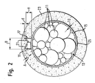
- Fig. 2 shows in cross section a cable set 13 according to the invention, the a plurality of electrical lines 11 leads and on the one according to the invention Positioning device is clamped, which has an annular, with a slot 25 provided carrier 15 and one on the radial
- the outside of the carrier 15 is arranged in one piece with the carrier 15 formed holding chamber 17, in which a connecting point 19th arranged between two or more lines 11 and by clamping tabs 21 of the holding device 17 is held in a clamp-fixing manner.
- the holding chamber 17 or the holding tabs 21 are designed such that the connection point 19 even when it is off-center Arrangement held in the holding chamber 17 in a reliable manner becomes.
- the wall thickness TD of the carrier is 15 approximately 1 mm
- the radial height H of the holding chamber 17 approximately 3 mm
- the thickness d of the retaining tabs 21 is approximately 1 mm
- the holding chamber 17 has a width B of about 6 mm and is for receiving of joints 19 with a thickness between about 1 mm to 2.9 mm and a width between about 1 mm to 5.7 mm. These dimensions are only examples and can vary depending on the application vary.
- the cable set 13 is in the area of the positioning device according to the invention 15, 17 surrounded with a seal in the form of a spout 23, the by foaming the positioning device 15, 17 to the cable set 13 has been molded.
- the wall thickness of the spout 23 in the area of Holding device 17 is selected such that the holding device 17 also the material of the spout 23 covered with a covering thickness of about 2 mm is.
- the means the positioning device 15, 17 positioned and fixed connection point 19 completely embedded in the sealing spout 23 and thus optimal against external influences, especially moisture protected.
- a positioning device according to the invention only one holding device 17 are preferred Embodiments arranged several distributed in the circumferential direction Holding devices 17 are provided, e.g. is shown in Fig. 1a. In FIG. 2, the others are only for the purpose of simplifying the illustration Holding devices 17 have been omitted. Ultimately, the number depends on a support 15 provided holding devices 17 of the respective Use case.
- connection point 19 The number of individual lines 11 which are connected to a connection point 19 can be connected to one another in principle. Can also deviating from the representations in FIGS. 1a, 1b and 2, also in each case a plurality of connection points 19 by means of a single holding device 17 be fixed on the carrier 15 and thus on the cable set 13.
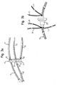
- 3a shows a positioning device according to the invention with a annular carrier 15 having a plurality of holding chambers 17.
- a connection point 19 wherein the two upper holding devices 17 each as passage chambers are formed and a total of six lines 11, each of which three are introduced from one side, connecting with each other Fix the connection point 19, while the lower one, which serves as the end chamber Holding device 17 a connection point between three of only one side led lines 11 fixed.
- the remaining cable set is on in FIG. 3a the positioning device according to the invention with the ring carrier 15 is plugged on, not shown.
- the carrier 15 and the holding devices 17 are not in one piece formed with each other, but the holding devices 17 are provided in the form of separate components, which are coupled to the carrier 15 can be, the connection provided for this principle in any way and e.g. as plug-in, snap-in or clip connection can be designed.
- This modular structure of the positioning device allows only the required number of Holding devices 17 need to be coupled to the carrier 15.
- FIG. 3b shows the finished cable set 13, to which a sealing sleeve 23 is molded which is the positioning device shown in FIG. 3a completely surrounds and thereby the individual connection points 19 perfectly protects against external influences such as moisture.
- the individual lines 11 through the three means the positioning device 15, 17 on the cable set 13 fixed connection points 19 are connected to each other, protruding from the cable set 13 shown. Basically, the diversion or integration these lines 11 each at an arbitrary distance from the sealing spout 23 take place.
- the sealing sleeve 23 is used for the sealing implementation of the cable set 13 through a passage opening in a motor vehicle component, e.g. through a vehicle front wall separating the vehicle interior from the engine compartment.
- the sealing sleeve 23 advantageously fulfills one Double function by keeping the drying area away from moisture Wet area protects and at the same time for the sealing of the connection points 19 worries.
- connection points 19 For sealing the connection points 19 and thus for the production of a cable set according to the invention - cf. in particular Fig. 3a and 3b - first of all the required connecting points 19 between the lines 11 e.g. by ultrasonic welding, resistance welding or crimped. Then the connection points 17 in the holding devices 17 of the invention Positioning device fixed. Attaching the carrier 15 to the Cable set 13 and - with a modular structure - assembly the positioning device by coupling the holding devices 17 with the carrier 15 can either before or after the manufacture of the Junctions 19 take place.
- connection points 19 by means of the positioning device on Cable set 13 are fixed, the positioning device is foamed around to produce a seal 23 with the required external shape.
- the preferred embodiment of the positioning device according to the invention with holding devices projecting radially from an annular carrier 15 17 ensures an intimate positive and non-positive Connection between the positioning device 15, 17 and the seal 23rd
Landscapes
- Engineering & Computer Science (AREA)
- Architecture (AREA)
- Civil Engineering (AREA)
- Structural Engineering (AREA)
- Installation Of Indoor Wiring (AREA)
Applications Claiming Priority (2)
| Application Number | Priority Date | Filing Date | Title |
|---|---|---|---|
| DE2002105328 DE10205328A1 (de) | 2002-02-08 | 2002-02-08 | Positioniereinrichtung |
| DE10205328 | 2002-02-08 |
Publications (2)
| Publication Number | Publication Date |
|---|---|
| EP1335463A2 true EP1335463A2 (fr) | 2003-08-13 |
| EP1335463A3 EP1335463A3 (fr) | 2004-08-25 |
Family
ID=27588503
Family Applications (1)
| Application Number | Title | Priority Date | Filing Date |
|---|---|---|---|
| EP03002470A Withdrawn EP1335463A3 (fr) | 2002-02-08 | 2003-02-05 | Dispositif de positionnement |
Country Status (2)
| Country | Link |
|---|---|
| EP (1) | EP1335463A3 (fr) |
| DE (1) | DE10205328A1 (fr) |
Cited By (2)
| Publication number | Priority date | Publication date | Assignee | Title |
|---|---|---|---|---|
| WO2007017332A1 (fr) * | 2005-08-05 | 2007-02-15 | Tesa Ag | Ruban adhesif a support en non-tisse dont une face est au moins partiellement enduite d'un adhesif charge de fibres et sensible a la pression |
| CN101559748B (zh) * | 2008-04-15 | 2012-10-24 | 通用汽车环球科技运作公司 | 高压车辆部件连接方法及设备 |
Family Cites Families (10)
| Publication number | Priority date | Publication date | Assignee | Title |
|---|---|---|---|---|
| DE3528130A1 (de) * | 1985-08-06 | 1987-02-12 | Kabel & Lackdrahtfab Gmbh | Vorgefertigte garnitur fuer ein geschirmtes, kunststoffisoliertes starkstromkabel |
| CA2071887A1 (fr) * | 1990-11-05 | 1992-05-06 | Keith M. Wagner | Harnais a fils muni d'une gaine d'acheminement |
| IT1245585B (it) * | 1991-03-25 | 1994-09-29 | Giuseppe Codrino | Procedimento operativo, atto a consentire l'applicazione a tenuta stagna, di strutture passaparete, su guaine protettive continue, di rivestimento per fasci di cavetti elettrici di cablaggio |
| DE4240171C2 (de) * | 1992-11-30 | 2001-08-02 | Abb Patent Gmbh | Spleißgehäuse für ein Starkstromkabel mit integrierten Lichtwellenleitern |
| DE4309538A1 (de) * | 1993-03-24 | 1994-09-29 | Rheydt Kabelwerk Ag | Verzweigungseinrichtung |
| DE29516216U1 (de) * | 1995-10-12 | 1996-01-25 | DSG-Canusa GmbH & Co. KG, 53340 Meckenheim | Dichtelement |
| DE19821657C2 (de) * | 1998-05-14 | 2002-11-14 | Hirt Manfred | Verkabelungssystem |
| DE19911415A1 (de) * | 1999-03-15 | 2000-05-18 | Siemens Ag | Kabelanschlußeinrichtung zur abisolierfreien Kontaktierung eines Kabels |
| EP1177951B1 (fr) * | 2000-08-02 | 2006-07-26 | Honda Giken Kogyo Kabushiki Kaisha | Structure de faisceau de cables |
| DE20103762U1 (de) * | 2001-03-03 | 2001-06-07 | Wilhelm Sihn jr. KG, 75223 Niefern-Öschelbronn | Geerdete Kabelarmatur |
-
2002
- 2002-02-08 DE DE2002105328 patent/DE10205328A1/de not_active Withdrawn
-
2003
- 2003-02-05 EP EP03002470A patent/EP1335463A3/fr not_active Withdrawn
Cited By (2)
| Publication number | Priority date | Publication date | Assignee | Title |
|---|---|---|---|---|
| WO2007017332A1 (fr) * | 2005-08-05 | 2007-02-15 | Tesa Ag | Ruban adhesif a support en non-tisse dont une face est au moins partiellement enduite d'un adhesif charge de fibres et sensible a la pression |
| CN101559748B (zh) * | 2008-04-15 | 2012-10-24 | 通用汽车环球科技运作公司 | 高压车辆部件连接方法及设备 |
Also Published As
| Publication number | Publication date |
|---|---|
| EP1335463A3 (fr) | 2004-08-25 |
| DE10205328A1 (de) | 2003-08-21 |
Similar Documents
| Publication | Publication Date | Title |
|---|---|---|
| EP1422459B1 (fr) | Système d'étanchéité | |
| EP2027629B1 (fr) | Connecteur enfichable blindé et son procédé de réalisation | |
| DE4433704C2 (de) | Steckbuchse | |
| DE69405679T2 (de) | Vorrichtung zur Sicherstellung der Kontinuität der elektrischen Abschirmung von Kabeln | |
| DE102015204851A1 (de) | Mehradriges Kabel und Verfahren zur Herstellung eines mehradrigen Kabels | |
| EP3711119A1 (fr) | Dispositif électrique de mise en contact de blindage de câble et connecteur électrique | |
| DE19701511C2 (de) | Tülle zur Durchführung von elektrischen Leitungen durch Wandungen, insbesondere in Kraftfahrzeugen | |
| EP0008603A1 (fr) | Couplage de ligne pour connecter deux lignes électriques | |
| WO1983000263A1 (fr) | Cable de raccordement pour appareil electrique | |
| DE29516216U1 (de) | Dichtelement | |
| DE69212140T2 (de) | Anschlusselement für elektrisches Kabel mit integriertem Markierungsträger | |
| DE3408135C2 (de) | Kupplungseinrichtung zum druckdichten Befestigen einer Druckmittelleitung an einem Druckmittelanschluß | |
| EP1335463A2 (fr) | Dispositif de positionnement | |
| DE4328240C2 (de) | Verfahren zur Herstellung eines Steckers und Spritzgießform zur Durchführung des Verfahrens | |
| DE1934666C3 (de) | Wasserdichte Wanddurchführung von elektrischen, von beiden Seiten an eine Trennwand herangeführte, unmittelbar miteinander über ihre Kontaktteile kuppelbare Leitungen | |
| DE9320414U1 (de) | Elektrische Steckverbindung | |
| EP0381024B1 (fr) | Conducteur de phase multifils et procédé pour l'installation d'un tel conducteur de phase multifils | |
| DE19525801C2 (de) | Vorrichtung zum elektrisch leitenden Verbinden von zwei elektrischen Leitungen | |
| EP0742121A2 (fr) | Faisceau de cables | |
| DE3501243A1 (de) | Vorrichtung zum stuetzen von in kabelmuffen einlaufenden kabelenden | |
| DE19921564A1 (de) | Kabeldurchführung | |
| DE102018222467A1 (de) | Leitungsanordnung mit einer Flüssigkeitsbarriere | |
| DE10059636B4 (de) | Tülle | |
| DE29519589U1 (de) | Abgedichteter elektrischer Stecker | |
| DE102018008165A1 (de) | Vorrichtung und Verfahren zur Anbindung von elektrischen Verbrauchern einer Außenhaut einer Fahrzeugkarosserie an ein Bordnetz des Fahrzeuges |
Legal Events
| Date | Code | Title | Description |
|---|---|---|---|
| PUAI | Public reference made under article 153(3) epc to a published international application that has entered the european phase |
Free format text: ORIGINAL CODE: 0009012 |
|
| AK | Designated contracting states |
Designated state(s): AT BE BG CH CY CZ DE DK EE ES FI FR GB GR HU IE IT LI LU MC NL PT SE SI SK TR |
|
| AX | Request for extension of the european patent |
Extension state: AL LT LV MK RO |
|
| PUAL | Search report despatched |
Free format text: ORIGINAL CODE: 0009013 |
|
| AK | Designated contracting states |
Kind code of ref document: A3 Designated state(s): AT BE BG CH CY CZ DE DK EE ES FI FR GB GR HU IE IT LI LU MC NL PT SE SI SK TR |
|
| AX | Request for extension of the european patent |
Extension state: AL LT LV MK RO |
|
| RIC1 | Information provided on ipc code assigned before grant |
Ipc: 7B 60R 16/02 B Ipc: 7H 02G 3/30 A |
|
| 17P | Request for examination filed |
Effective date: 20040813 |
|
| AKX | Designation fees paid |
Designated state(s): AT BE BG CH CY CZ DE DK EE ES FI FR GB GR HU IE IT LI LU MC NL PT SE SI SK TR |
|
| STAA | Information on the status of an ep patent application or granted ep patent |
Free format text: STATUS: THE APPLICATION IS DEEMED TO BE WITHDRAWN |
|
| 18D | Application deemed to be withdrawn |
Effective date: 20100901 |