EP1335465A1 - Procédé de fabrication d'un dispositif de transmission de puissance électrique - Google Patents
Procédé de fabrication d'un dispositif de transmission de puissance électrique Download PDFInfo
- Publication number
- EP1335465A1 EP1335465A1 EP03290097A EP03290097A EP1335465A1 EP 1335465 A1 EP1335465 A1 EP 1335465A1 EP 03290097 A EP03290097 A EP 03290097A EP 03290097 A EP03290097 A EP 03290097A EP 1335465 A1 EP1335465 A1 EP 1335465A1
- Authority
- EP
- European Patent Office
- Prior art keywords
- support plate
- bars
- plate
- manufacturing
- conductive
- Prior art date
- Legal status (The legal status is an assumption and is not a legal conclusion. Google has not performed a legal analysis and makes no representation as to the accuracy of the status listed.)
- Granted
Links
- 230000005540 biological transmission Effects 0.000 title claims abstract description 23
- 238000000034 method Methods 0.000 title claims abstract description 6
- 238000004519 manufacturing process Methods 0.000 claims abstract description 15
- 239000000463 material Substances 0.000 claims abstract description 14
- 238000000465 moulding Methods 0.000 claims abstract description 12
- 230000000295 complement effect Effects 0.000 claims abstract description 5
- 230000006835 compression Effects 0.000 claims abstract description 5
- 238000007906 compression Methods 0.000 claims abstract description 5
- 238000002347 injection Methods 0.000 claims abstract description 4
- 239000007924 injection Substances 0.000 claims abstract description 4
- 238000009417 prefabrication Methods 0.000 claims description 3
- 239000012768 molten material Substances 0.000 claims description 2
- 239000002131 composite material Substances 0.000 description 4
- 125000006850 spacer group Chemical group 0.000 description 4
- 239000004020 conductor Substances 0.000 description 3
- 229920000728 polyester Polymers 0.000 description 3
- YMHOBZXQZVXHBM-UHFFFAOYSA-N 2,5-dimethoxy-4-bromophenethylamine Chemical compound COC1=CC(CCN)=C(OC)C=C1Br YMHOBZXQZVXHBM-UHFFFAOYSA-N 0.000 description 2
- 241000545067 Venus Species 0.000 description 2
- 239000003365 glass fiber Substances 0.000 description 2
- 238000003754 machining Methods 0.000 description 2
- 238000005259 measurement Methods 0.000 description 2
- 230000002093 peripheral effect Effects 0.000 description 2
- RYGMFSIKBFXOCR-UHFFFAOYSA-N Copper Chemical compound [Cu] RYGMFSIKBFXOCR-UHFFFAOYSA-N 0.000 description 1
- 239000004952 Polyamide Substances 0.000 description 1
- 229910052802 copper Inorganic materials 0.000 description 1
- 239000010949 copper Substances 0.000 description 1
- 238000005336 cracking Methods 0.000 description 1
- 238000004132 cross linking Methods 0.000 description 1
- 230000004927 fusion Effects 0.000 description 1
- 238000010438 heat treatment Methods 0.000 description 1
- 239000000696 magnetic material Substances 0.000 description 1
- 239000011159 matrix material Substances 0.000 description 1
- 239000002184 metal Substances 0.000 description 1
- 229910052751 metal Inorganic materials 0.000 description 1
- 230000007935 neutral effect Effects 0.000 description 1
- 238000013021 overheating Methods 0.000 description 1
- 239000004033 plastic Substances 0.000 description 1
- 229920002647 polyamide Polymers 0.000 description 1
- -1 polybutylene terephthalate Polymers 0.000 description 1
- 229920001707 polybutylene terephthalate Polymers 0.000 description 1
- 239000011347 resin Substances 0.000 description 1
- 229920005989 resin Polymers 0.000 description 1
- 229910001220 stainless steel Inorganic materials 0.000 description 1
- 239000010935 stainless steel Substances 0.000 description 1
Images

Classifications
-
- H—ELECTRICITY
- H02—GENERATION; CONVERSION OR DISTRIBUTION OF ELECTRIC POWER
- H02G—INSTALLATION OF ELECTRIC CABLES OR LINES, OR OF COMBINED OPTICAL AND ELECTRIC CABLES OR LINES
- H02G5/00—Installations of bus-bars
- H02G5/02—Open installations
- H02G5/025—Supporting structures
-
- H—ELECTRICITY
- H01—ELECTRIC ELEMENTS
- H01F—MAGNETS; INDUCTANCES; TRANSFORMERS; SELECTION OF MATERIALS FOR THEIR MAGNETIC PROPERTIES
- H01F27/00—Details of transformers or inductances, in general
- H01F27/02—Casings
- H01F27/04—Leading of conductors or axles through casings, e.g. for tap-changing arrangements
Definitions
- the present invention relates to a method for manufacturing a device for transmitting electrical power through a wall, of the type comprising at least two conductive bars each having a cross section greater than 700 mm 2 and a support plate common to said bars conductive, each conductive bar passing through the support plate through an orifice and projecting on either side of the support plate.
- Such power transmission devices are used in particular for the passage of electrical conductors through a wall of a high capacity transformer.
- the support plate of the power transmission device When the intensity of the current flowing in each bar is greater at 1000 amps for an industrial frequency for example of 50 Hz, the support plate of the power transmission device must be made of a non-magnetic material to avoid overheating magnetic due to the circulation of eddy electric currents in the bars.
- the wall is then for example made of stainless steel non-magnetic, plastic or a composite material.
- the plate is formed for example of a composite material with a high load of glass fibers.
- the matrix of the composite material is composed for example polyester.
- transmission devices comprising several conductive bars, the middle part of which is embedded in the same insulating plate, this plate being overmolded on the conductive bars in a suitable resin.
- Such devices have the disadvantage of being subject to training cracks in the support plate in the vicinity of the bars, due to the thermal expansion of the bars.
- the phenomenon is particularly marked when the bars have, in cross section, an oblong shape, the width of each bar being much greater than its thickness.
- the object of the invention is to propose a method for manufacturing a device transmission of electrical power, which gives the device a low manufacturing cost and good crack resistance of the device in case of thermal expansion of the bars.
- the device 10 illustrated in FIG. 1 is intended for the transmission of electrical power through a wall. Such a device, within the meaning of the present description, is adapted to allow the transmission of an intensity maximum greater than 500 A per phase.
- the illustrated device is suitable in particular for transmission to through this wall of the three phases and the neutral of an electric current three-phase high power.
- the electric current carried is assumed of high intensity, this being in particular of the order or greater than 1000 A per phase.
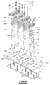
- the device essentially comprises an insulating support plate 12 and in particular four through conductive bars 14A, 14B, 14C and 16 for the transmission of four separate electric currents through of the plate.
- the conductive bars each protrude on either side of the plate.
- the device further comprises ten small diameter bushings 18 allowing the circulation of low intensity electric current between two sides of the plate 12.
- the plate 12 is of constant thickness and is generally rectangular. It generally has four holes rectangular 20A, 20B, 20C and 22 allowing the passage of the bars 14A, 14B, 14C and 16 respectively.
- each orifice of passage of the bars is bordered by a peripheral flaring 23 defining a support seat for a seal.
- the flare 23 generally defines a bowl whose concave annular bottom is inclined and converges towards the central part of the bottom, where the opening for passage of the bar opens.
- the plate 12 is crossed by ten circular conduits 24 for bushings 18.
- the conduits 24 are each bordered on one face of the plate 12 of an annular cup 26 suitable for receiving an O-ring not shown.
- the plate 12 has holes 30 allowing its fixing to a wall, for example by means of screws. These holes are spared regularly on the periphery of the plate.
- the plate 12 is formed in a mold from of a malleable material.
- the orifices 20A, 20B, 20C and 22 and the associated flares 23 came from molding.
- the conductive bars 14A, 14B, 14C are made of metal and in particular copper. They have a cross section greater than 700 mm 2 . These bars are for example generally rectangular in section. The dimensions of the bars are for example 120 mm x 12 mm.
- the bar 16 is of smaller section. For example, it has dimensions equal to 63 mm x 12 mm.
- bus bars for higher intensity at 2000 A have in section a width at least six times greater than their thickness.
- the orifices 20A, 20B, 20C and 22 for passing the bars have a shape complementary to that of the bars and have dimensions slightly to provide an expansion gap between the bars and the plate 12.
- the bars At each of their ends, the bars have holes adapted for receiving means for fixing electrical cables in front be connected to it, on both sides of the plate 12.
- the bars are each crossed right through by two through holes 32 arranged on either side of the plate and suitable for receiving pins 34 for axial immobilization of the bars relative to plate 12.
- a first end seal 36A has a complementary profile in section to that of the peripheral flaring 23 of the orifices 20A, 20B, 20C and 22.
- the seal 36A has, depending on its turned surface towards the plate 12 a bevelled surface whose normal is turned towards the outside of the seal.
- the second end seal 36B is identical to the first end seal but it is arranged in the opposite direction. Between these is enclosed by a rigid spacer 36C.
- a ring 40 for compressing the seals is added around each bar and is kept immobilized relative to the plate 12 by clamping screws 42 engaged in the plate 12.
- Each ring has internally a cup-shaped flare suitable for reception of the second end seal 36B. This release is gradually divergent towards the face of the ring facing the plate 12.
- Each bushing 18 comprises a threaded rod 60 comprising at each end a nut 62. It further comprises a spacer 64 adapted to be clamped between an end nut 62 and the plate 12 in support on the O-ring placed in the bowl 26.
- the rods 60 are intended for the transport of electrical measurement or control signals having a low intensity. Their cross section is less than 200 mm 2 .
- the plate 12 is first prefabricated by molding.
- the plate 12 is first injected alone in a cavity of constant dimensions of a mold from of a fluidized material by heating.
- the material used to inject the plate is for example a polyamide, a polybutylene terephthalate or a polyester.
- the mold used for the manufacture of the plate 12 is constituted by example of two assembled half-shells, each presenting an imprint. These two half-shells are such that, when they are joined to each other, the two footprints which are formed there delimit together an enclosed space defining the external shape of the plate 12. Four movable drawers are engaged in this closed space to form the orifices 20A, 20B, 20C and 22 for passage of the bars.
- movable drawers, or protrusions additional protruding into each footprint are provided for delimit the passage conduits of the bushings and the fixing holes 30 of the plate.
- the plate 12 is taken out of the mold.
- the plate 12 is formed from an ingot of malleable material such as polyester. This ingot, while it is heated, is pressed between two jaws of a jaw defining a mold whose shape of the interior cavity corresponds exactly, when the jaw is closed, in the shape of the plate 12, in particular with the orifices 20A, 20B, 20C and 22 and the conduits 24.
- the plate 12 is obtained after crosslinking the pressed ingot and extracting it from the mold.
- the bars 14A, 14B, 14C and 16 are engaged in the corresponding holes.
- the two seals 36A, 36B, the spacer 36C and the retaining rings 40 are engaged around each bar.
- the pins are then inserted into the holes for axially immobilize the bars.
- the rings are then tightened against the plate 20 by fitting clamping screws 42, in order to ensure compression radially seals against bars 14A, 14B, 14C and 16 and axially between the plate 12 and the rings 40.
- crossings 18 are set up by engagement rods 60 through conduits 24.
- O-rings and spacers 64 are engaged around the rods 60 and the end nuts 62 are screwed at each end of the rods 60.
- An electrical power transmission device as described here can be manufactured at low cost as long as plate 12 is obtained by molding.
- sufficient functional clearance may be formed between the plate 12 and the bars, at the level of the receiving orifices bars. Thus, any risk of cracking of the plate 12 is eliminated during the expansion of the busbars.
- the device allows both the transmission of information and power, for a low cost.
- the conduits 24 ensuring the passage of the crossings formed by the rods 60 came from molding during the prefabrication of the plate 12.
Landscapes
- Engineering & Computer Science (AREA)
- Power Engineering (AREA)
- Moulds For Moulding Plastics Or The Like (AREA)
Abstract
Description
- préfabriquer dans un moule, à partir d'un matériau initialement malléable, la plaque de support présentant les orifices de passage pour les barres conductrices, les orifices étant venus de moulage ;
- introduire une barre conductrice dans chaque orifice de la plaque de support préalablement moulée ; et
- assurer la liaison entre les barres conductrices et la plaque de support.
- la plaque de support est préfabriquée par injection de matière en fusion dans une cavité de dimensions constantes du moule ;
- la plaque de support est préfabriquée par compression d'un lingot de matière malléable entre les mors complémentaires d'une mâchoire définissant le moule ;
- il comporte une étape consistant à assurer une étanchéité entre chaque barre conductrice et la plaque de support au cours de laquelle au moins un joint d'étanchéité est rapporté autour de chaque barre conductrice, et le ou chaque joint est enserré entre la plaque de support et une bague rapportée autour de chaque barre, la bague et la plaque de support étant maintenues sollicitées l'une vers l'autre ;
- les barres conductrices ont, en section, une largeur au moins six fois supérieure à leur épaisseur ; et
- lors de la préfabrication dans un moule de la plaque de support, des conduits de passage de tiges pour la transmission de courants électriques de faible intensité sont formés au travers de la plaque, lesdits conduits étant venus de moulage, et une tige conductrice dont la section transversale est inférieure à 200 mm2 est introduite et immobilisée dans chaque conduit de la plaque de support préalablement moulée.
- La figure 1 est une vue en perspective d'un dispositif de transmission de puissance électrique ; et
- La figure 2 est une vue en perspective éclatée du même dispositif.
Claims (6)
- Procédé de fabrication d'un dispositif (10) de transmission de puissance au travers d'une paroi comportant au moins deux barres conductrices (14A, 14B, 14C, 16) ayant chacune une section transversale supérieure à 700 mm2 et une plaque de support (12) commune auxdites barres conductrices, chaque barre conductrice traversant la plaque de support (12) au travers d'un orifice (20A, 20B, 20C, 22) et faisant saillie de part et d'autre de la plaque de support (12), caractérisé en ce qu'il comporte les étapes de :préfabriquer dans un moule, à partir d'un matériau initialement malléable, la plaque de support (12) présentant les orifices (20A, 20B, 20C, 22) de passage pour les barres conductrices (14A, 14B, 14C, 16), les orifices (20A, 20B, 20C, 22) étant venus de moulage ;introduire une barre conductrice (14A, 14B, 14C, 16) dans chaque orifice (20A, 20B, 20C, 22) de la plaque de support (12) préalablement moulée ; etassurer la liaison entre les barres conductrices (14A, 14B, 14C, 16) et la plaque de support (12).
- Procédé de fabrication selon la revendication 1, caractérisé en ce que la plaque de support (12) est préfabriquée par injection de matière en fusion dans une cavité de dimensions constantes du moule.
- Procédé de fabrication selon la revendication 1, caractérisé en ce que la plaque de support (12) est préfabriquée par compression d'un lingot de matière malléable entre les mors complémentaires d'une mâchoire définissant le moule.
- Procédé de fabrication selon l'une quelconque des revendications précédentes, caractérisé en ce qu'il comporte une étape consistant à assurer une étanchéité entre chaque barre conductrice (14A, 14B, 14C, 16) et la plaque de support (12) au cours de laquelle au moins un joint d'étanchéité (36A, 36B, 36C) est rapporté autour de chaque barre conductrice, et le ou chaque joint (36A, 36B, 36C) est enserré entre la plaque de support (12) et une bague (40) rapportée autour de chaque barre, la bague et la plaque de support (12) étant maintenues sollicitées l'une vers l'autre.
- Procédé de fabrication selon l'une quelconque des revendications précédentes, caractérisé en ce que les barres conductrices (14A, 14B, 14C, 16) ont, en section, une largeur au moins six fois supérieure à leur épaisseur.
- Procédé de fabrication selon l'une quelconque des revendications précédentes, caractérisé en ce que, lors de la préfabrication dans un moule de la plaque de support (12), des conduits (24) de passage de tiges pour la transmission de courants électriques de faible intensité sont formés au travers de la plaque, lesdits conduits (24) étant venus de moulage, et en ce qu'une tige conductrice (60) dont la section transversale est inférieure à 200 mm2 est introduite et immobilisée dans chaque conduit (24) de la plaque de support (12) préalablement moulée.
Applications Claiming Priority (2)
| Application Number | Priority Date | Filing Date | Title |
|---|---|---|---|
| FR0201586 | 2002-02-08 | ||
| FR0201586A FR2835960B1 (fr) | 2002-02-08 | 2002-02-08 | Procede de fabrication d'un dispositif de transmission de puissance electrique |
Publications (2)
| Publication Number | Publication Date |
|---|---|
| EP1335465A1 true EP1335465A1 (fr) | 2003-08-13 |
| EP1335465B1 EP1335465B1 (fr) | 2017-03-29 |
Family
ID=27589613
Family Applications (1)
| Application Number | Title | Priority Date | Filing Date |
|---|---|---|---|
| EP03290097.9A Expired - Lifetime EP1335465B1 (fr) | 2002-02-08 | 2003-01-14 | Procédé de fabrication d'un dispositif de transmission de puissance électrique |
Country Status (2)
| Country | Link |
|---|---|
| EP (1) | EP1335465B1 (fr) |
| FR (1) | FR2835960B1 (fr) |
Cited By (6)
| Publication number | Priority date | Publication date | Assignee | Title |
|---|---|---|---|---|
| EP2264849A1 (fr) | 2009-06-16 | 2010-12-22 | Starkstrom-gerätebau GmbH | Support de connexion pour un transformateur et transformateur avec ce support de connexion |
| EP2568554A1 (fr) * | 2011-09-12 | 2013-03-13 | ABB Technology AG | Support intégré pour la fixation de bus électriques |
| CN103066539A (zh) * | 2012-12-30 | 2013-04-24 | 江苏辉能达电气有限公司 | 母线槽专用型材 |
| EP2110914A3 (fr) * | 2008-04-18 | 2013-10-23 | RITTAL GmbH | Dispositif de barre omnibus |
| EP4145470A1 (fr) * | 2021-09-02 | 2023-03-08 | Hwaseung Corporation Co., Ltd. | Douille isolante |
| EP4636787A1 (fr) * | 2024-04-15 | 2025-10-22 | Pioch | Dispositif passe-barre et procédé de montage de ce dispositif |
Families Citing this family (2)
| Publication number | Priority date | Publication date | Assignee | Title |
|---|---|---|---|---|
| WO2013028331A1 (fr) * | 2011-08-24 | 2013-02-28 | Abb Technology Ag | Structure de manchon de serre-barres d'appareillage de commutation |
| USD1054380S1 (en) | 2021-07-15 | 2024-12-17 | Hwaseung Corporation Co., Ltd | Busbar bushing |
Citations (2)
| Publication number | Priority date | Publication date | Assignee | Title |
|---|---|---|---|---|
| FR2545641A1 (fr) * | 1983-05-04 | 1984-11-09 | Pioch Rene | Passe-barre a barre flottante destine aux sorties de transformateur |
| EP0944101A1 (fr) * | 1998-03-18 | 1999-09-22 | Pioch S.A. | Dispositif passe-barre et traversée électrique de paroi |
-
2002
- 2002-02-08 FR FR0201586A patent/FR2835960B1/fr not_active Expired - Lifetime
-
2003
- 2003-01-14 EP EP03290097.9A patent/EP1335465B1/fr not_active Expired - Lifetime
Patent Citations (2)
| Publication number | Priority date | Publication date | Assignee | Title |
|---|---|---|---|---|
| FR2545641A1 (fr) * | 1983-05-04 | 1984-11-09 | Pioch Rene | Passe-barre a barre flottante destine aux sorties de transformateur |
| EP0944101A1 (fr) * | 1998-03-18 | 1999-09-22 | Pioch S.A. | Dispositif passe-barre et traversée électrique de paroi |
Cited By (7)
| Publication number | Priority date | Publication date | Assignee | Title |
|---|---|---|---|---|
| EP2110914A3 (fr) * | 2008-04-18 | 2013-10-23 | RITTAL GmbH | Dispositif de barre omnibus |
| EP2264849A1 (fr) | 2009-06-16 | 2010-12-22 | Starkstrom-gerätebau GmbH | Support de connexion pour un transformateur et transformateur avec ce support de connexion |
| WO2010145859A1 (fr) * | 2009-06-16 | 2010-12-23 | Starkstrom-Gerätebau Gmbh | Bornier pour transformateur et transformateur équipé de ce bornier |
| EP2568554A1 (fr) * | 2011-09-12 | 2013-03-13 | ABB Technology AG | Support intégré pour la fixation de bus électriques |
| CN103066539A (zh) * | 2012-12-30 | 2013-04-24 | 江苏辉能达电气有限公司 | 母线槽专用型材 |
| EP4145470A1 (fr) * | 2021-09-02 | 2023-03-08 | Hwaseung Corporation Co., Ltd. | Douille isolante |
| EP4636787A1 (fr) * | 2024-04-15 | 2025-10-22 | Pioch | Dispositif passe-barre et procédé de montage de ce dispositif |
Also Published As
| Publication number | Publication date |
|---|---|
| EP1335465B1 (fr) | 2017-03-29 |
| FR2835960A1 (fr) | 2003-08-15 |
| FR2835960B1 (fr) | 2004-05-14 |
Similar Documents
| Publication | Publication Date | Title |
|---|---|---|
| EP1894442B1 (fr) | Dispositif de chauffage par induction et procede de fabrication de pieces a l'aide d'un tel dispositif | |
| EP1728411B1 (fr) | Procede pour chauffer des materiaux en vue de produire des objets et dispositif mettant en oeuvre ce procede | |
| CA2138634C (fr) | Ligne a haute tension a isolation gazeuse pour longue distance | |
| EP1924415B1 (fr) | Dispositif de transformation de materiaux utilisant un chauffage par induction | |
| EP0660479B1 (fr) | Câble monophase à isolation gazeuse pour le transport d'électricité | |
| EP1335465B1 (fr) | Procédé de fabrication d'un dispositif de transmission de puissance électrique | |
| EP0120787A1 (fr) | Procédé de moulage du revêtement isolant d'un isolateur électrique organique de grande longueur | |
| FR2600838A1 (fr) | Moteur electrique a palier perfectionne | |
| MC2159A1 (fr) | Piece de raccordement du type a resistance electrique perfectionnee pour la reunion par thermosoudage d'elements en matiere plastique | |
| CA2033818A1 (fr) | Procede d'alimentation en energie electrique d'une resistance circuit electrique prevu a cet effet et utilisations de ce circuit | |
| EP0423665A1 (fr) | Ligne électrique blindée et son procédé de fabrication | |
| FR2552704A1 (fr) | Outillage a canal chauffant pour l'amenee d'une matiere plastique en fusion a un moule d'injection | |
| FR2716769A1 (fr) | Dispositif de commande et de contrôle d'un moteur électronique, support utilisable dans un tel dispositif et utilisation de ce support pour la réalisation d'une batterie d'éléments d'accumulateurs électriques. | |
| FR3035212A1 (fr) | Sonde de temperature | |
| FR2876214A1 (fr) | Disque isolant de support d'un conducteur et ensemble electrique comprenant ce disque. | |
| FR2716521A1 (fr) | Raccord angulaire. | |
| EP1057583A1 (fr) | Plateau magnétique pour la fixation de moules sur des machines à injecter | |
| FR2803558A1 (fr) | Procede pour la realisation et la mise en place d'une enveloppe en elastomere autour d'un corps plein ou creux | |
| FR2800203A1 (fr) | Disque de contact pour plaques conductrices de barres de bus | |
| FR2498022A1 (fr) | Procede et equipement de realisation de jonctions de conducteurs electriques a isolant sec pour tensions elevees | |
| EP1178496B1 (fr) | Procédé de fabrication d'un isolateur électrique à tige | |
| US20020170735A1 (en) | Electric cable joints and methods of making them | |
| FR2620222A1 (fr) | Detecteur de proximite inductif et son procede de fabrication | |
| EP0696099A1 (fr) | Canalisation électrique à zone d'éclissage étanche | |
| EP2337037A2 (fr) | Procédé de fabrication d'un aimant moulé. |
Legal Events
| Date | Code | Title | Description |
|---|---|---|---|
| PUAI | Public reference made under article 153(3) epc to a published international application that has entered the european phase |
Free format text: ORIGINAL CODE: 0009012 |
|
| AK | Designated contracting states |
Designated state(s): AT BE BG CH CY CZ DE DK EE ES FI FR GB GR HU IE IT LI LU MC NL PT SE SI SK TR |
|
| AX | Request for extension of the european patent |
Extension state: AL LT LV MK RO |
|
| 17P | Request for examination filed |
Effective date: 20031108 |
|
| AKX | Designation fees paid |
Designated state(s): DE GB IT |
|
| GRAP | Despatch of communication of intention to grant a patent |
Free format text: ORIGINAL CODE: EPIDOSNIGR1 |
|
| INTG | Intention to grant announced |
Effective date: 20161028 |
|
| GRAS | Grant fee paid |
Free format text: ORIGINAL CODE: EPIDOSNIGR3 |
|
| GRAA | (expected) grant |
Free format text: ORIGINAL CODE: 0009210 |
|
| AK | Designated contracting states |
Kind code of ref document: B1 Designated state(s): DE GB IT |
|
| REG | Reference to a national code |
Ref country code: GB Ref legal event code: FG4D Free format text: NOT ENGLISH |
|
| REG | Reference to a national code |
Ref country code: DE Ref legal event code: R096 Ref document number: 60350063 Country of ref document: DE |
|
| REG | Reference to a national code |
Ref country code: DE Ref legal event code: R097 Ref document number: 60350063 Country of ref document: DE |
|
| PLBE | No opposition filed within time limit |
Free format text: ORIGINAL CODE: 0009261 |
|
| STAA | Information on the status of an ep patent application or granted ep patent |
Free format text: STATUS: NO OPPOSITION FILED WITHIN TIME LIMIT |
|
| PG25 | Lapsed in a contracting state [announced via postgrant information from national office to epo] |
Ref country code: IT Free format text: LAPSE BECAUSE OF FAILURE TO SUBMIT A TRANSLATION OF THE DESCRIPTION OR TO PAY THE FEE WITHIN THE PRESCRIBED TIME-LIMIT Effective date: 20170329 |
|
| 26N | No opposition filed |
Effective date: 20180103 |
|
| PGFP | Annual fee paid to national office [announced via postgrant information from national office to epo] |
Ref country code: GB Payment date: 20220120 Year of fee payment: 20 Ref country code: DE Payment date: 20220114 Year of fee payment: 20 |
|
| REG | Reference to a national code |
Ref country code: DE Ref legal event code: R071 Ref document number: 60350063 Country of ref document: DE |
|
| REG | Reference to a national code |
Ref country code: GB Ref legal event code: PE20 Expiry date: 20230113 |
|
| PG25 | Lapsed in a contracting state [announced via postgrant information from national office to epo] |
Ref country code: GB Free format text: LAPSE BECAUSE OF EXPIRATION OF PROTECTION Effective date: 20230113 |