EP1335501A1 - Verfahren zur Stromleitungskommunikation und Kopplervorrichtung - Google Patents
Verfahren zur Stromleitungskommunikation und Kopplervorrichtung Download PDFInfo
- Publication number
- EP1335501A1 EP1335501A1 EP03290243A EP03290243A EP1335501A1 EP 1335501 A1 EP1335501 A1 EP 1335501A1 EP 03290243 A EP03290243 A EP 03290243A EP 03290243 A EP03290243 A EP 03290243A EP 1335501 A1 EP1335501 A1 EP 1335501A1
- Authority
- EP
- European Patent Office
- Prior art keywords
- phase
- cable
- conductors
- link
- generator
- Prior art date
- Legal status (The legal status is an assumption and is not a legal conclusion. Google has not performed a legal analysis and makes no representation as to the accuracy of the status listed.)
- Granted
Links
Images

Classifications
-
- H—ELECTRICITY
- H04—ELECTRIC COMMUNICATION TECHNIQUE
- H04B—TRANSMISSION
- H04B3/00—Line transmission systems
- H04B3/54—Systems for transmission via power distribution lines
- H04B3/56—Circuits for coupling, blocking, or by-passing of signals
-
- H—ELECTRICITY
- H04—ELECTRIC COMMUNICATION TECHNIQUE
- H04B—TRANSMISSION
- H04B2203/00—Indexing scheme relating to line transmission systems
- H04B2203/54—Aspects of powerline communications not already covered by H04B3/54 and its subgroups
- H04B2203/5462—Systems for power line communications
- H04B2203/5466—Systems for power line communications using three phases conductors
-
- H—ELECTRICITY
- H04—ELECTRIC COMMUNICATION TECHNIQUE
- H04B—TRANSMISSION
- H04B2203/00—Indexing scheme relating to line transmission systems
- H04B2203/54—Aspects of powerline communications not already covered by H04B3/54 and its subgroups
- H04B2203/5462—Systems for power line communications
- H04B2203/5483—Systems for power line communications using coupling circuits
- H04B2203/5487—Systems for power line communications using coupling circuits cables
Definitions
- the present invention relates to improvements brought in the field of transmission information by PLC signals (Online Carrier Current) in an underground cable transporting electrical energy three-phase, and more precisely the invention relates to the transmission of information by high LC signals frequencies in an underground power transmission cable electrical three-phase, including, although not exclusively, low voltage, four-wire type conductors having an uninsulated neutral conductor in contact galvanic with conductive cable shielding sheath or of the type with three phase conductors surrounded by a neutral device.
- PLC signals Online Carrier Current
- the problem which is at the base of the invention lies in the fact that, if the three-phase is commonly used at industrial frequencies (low frequency of 50 Hz, 60 Hz, ...), it is not in the field of high frequencies, in particular because the generators of HF signals are bipolar: these generators are therefore not connectable only between two phases or between phase and neutral.
- the three-phase underground electrical energy transmission cables comprise three phase conductors ⁇ 1 , ⁇ 2 , ⁇ 3 and a neutral conductor N.
- This neutral conductor may be in the form of a fourth conductor which is physically in contact with the inner face of a metallic steel sheath surrounding the four conductors: this is the case of the type cable HN 33S33 or NFC 33-210 which is commonly used in France.
- This neutral conductor can also be peripheral, especially aluminum, and surround the three phase conductors: this is the case of the HN 33S32 type cable which is also used in France and some foreign countries.
- the object of the invention is to propose means - method and device - capable of optimal propagation of the signal CPL HF and a good single-phase / three-phase conversion to the right of the connections.
- the invention proposes, according to a first aspect, a method of transmitting information by high frequency LC signals in a four-conductor type three-phase underground electrical energy transmission cable including a neutral conductor galvanic contact with a conductive shielding sheath of the cable or of the three-phase-phase type surrounded by a peripheral neutral, characterized by energizing a propagation mode of the bipolar differential mode type cable by connecting a bipolar output CPL HF signal generator, on the one hand, between the two opposite phase conductors ( ⁇ 1 , ⁇ 3 ) united to one another and, on the other hand, to the driver of the other phase ( ⁇ 2 ), by virtue of which a broadband modal coupling is provided between said bipolar output CPL HF signal generator and said low voltage three-phase underground cable.
- the "common” mode is the transposition, for CPL HF signals, the coupling usually for low frequency LC signals (ie for frequencies below about 150 kHz).
- the laboratory measurements have made it possible to evidence that mitigation in the "common” mode was significantly larger than the attenuations in the "symmetrical” and “transverse” modes because of the presence cable steel shielding that introduces losses considerable due to its driver characteristics ferromagnetic. As a result, the "common” mode is not conducive to the transmission of data.
- the "symmetrical" and “transverse” modes have very interesting properties for the transmission of data. Nevertheless, the "symmetrical” mode only involves the two conductors of the opposite phases ( ⁇ 1 , ⁇ 3 ): all the energy transmitted to the cable, with such a coupling, will remain confined between the two conductors used and the crosstalk on the driver next to the other phase ( ⁇ 2 ) will then be too weak for this coupling to be exploited in practice.
- the excitation coupling of the "transverse" mode provides a gain from 4 to 5 dB, whatever the frequency, compared to classical coupling.
- the generator delivered RF signals with a frequency scanning of monochromatic lines between 1 MHz and 30 MHz.
- the reception was made downstream from the departure, level of connections of customers connected on an artery three-phase underground distribution.
- the said second link is a simple wire link.
- the said second link includes a capacitor.
- it comprises a third connection between said first terminal of the generator and the neutral of the cable with the interposition of a filtering coil, to constitute an integrated power supply of the generator, and a second filter coil is connected in parallel with the capacitor of the aforesaid second link.
- the components used for the realization of a coupling device according to the invention which exploits the "transverse" clean mode are only components passive (capacitors, inductors): this coupling device does not include active components nor transformer (s) coupling.
- the beach Frequency operation is wide and covers the 1 MHz - 30 MHz band dedicated to the transmission of signals CPL HF.
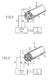
- an electric cable A capable of constituting an underground three-phase electrical transport pipe, in particular a low-voltage pipe, comprises three phase conductors designated respectively by the references 1 (phase ⁇ 1 ), 2 ( phase ⁇ 2 ) and 3 (phase ⁇ 3 ).
- a fourth conductor 4 is a neutral conductor N which is in galvanic contact with a metallic jacket or sheath 5, for example made of steel, which surrounds the conductors (HN 33S33 type underground cable, the most widely used in France).
- a generator G LC bipolar high frequency signal output is coupled (typically by means of an unillustrated PLC modem) to the three conductors 1, 2, 3 phases ⁇ 1, ⁇ 2, and ⁇ 3 respectively (via respective decoupling capacitors not shown in the drawing), so as to excite a propagation mode proper to the bipolar differential mode type cable and to provide a broadband modal coupling frequency .
- an electric cable B capable of constituting an underground three-phase electrical transmission pipe, in particular a low-voltage pipe, comprises three phase conductors respectively 1 (phase ⁇ 1 ), 2 (phase ⁇ 2 ) and 3 ( phase ⁇ 3 ), but the neutral conductor is here peripheral (underground cable type HN 33S32, used in France, and abroad).
- connection of the HF signal generator GF HF to bipolar output to all three phase 1 to 3 conductors done, as in the previous case, through a modal coupler broadband in frequency so that is excited a proper propagation mode of the cable of the bipolar differential mode type.
- FIG. 3 illustrates the electrical diagram of a modal coupler with a wide frequency band according to the invention for carrying out the method of the invention consisting in exciting a propagation mode proper to the bipolar differential mode type cable.
- a first link 6 is established, via a capacitor C 1 , between an output terminal 7 of the generator G and a midpoint M of a connection 8 joining the two conductors 1 (phase ⁇ 1 ) and 3 (phase ⁇ 3 ), with the interposition of two capacitors C ' 1 between the midpoint M and the respective phases ⁇ 1 and ⁇ 3 .
- a second link 9 is established, via a capacitor C 2 , between the other output terminal 10 of the generator G and the other conductor 2 (phase ⁇ 2 ).
- All the capacitors C 1 , C 2 , C ' 1 have the same capacitance (for example typically 10 nF) and the coupler thus constituted is of symmetrical structure.
- the capacitor C 2 is present in the second link 9 only to symmetrize the two links 6 and 9 and thus correspond to the capacitor C 1 of the first link 6.
- the capacitor C 2 is not strictly essential and the second output terminal 10 of the generator G can be connected to the conductor 2 of the phase 2 directly, by a simple wire connection, as illustrated in FIG. 4.
- a third link 11 is provided between the first output 7 of the generator G to the neutral conductor N via an inductance coil L ensuring the decoupling of the frequency of the network (typically 50 Hz).
- An integrated power supply can also be used in the case of the embodiment of FIG. 3. It is then possible, as illustrated in FIG. 5, to provide for this purpose the same mounting as in FIG. 4, that is, say a third link 11 between the first output 7 of the generator G to the neutral conductor N via an inductance coil L ensuring the decoupling of the frequency of the network.
Landscapes
- Engineering & Computer Science (AREA)
- Power Engineering (AREA)
- Computer Networks & Wireless Communication (AREA)
- Signal Processing (AREA)
- Cable Transmission Systems, Equalization Of Radio And Reduction Of Echo (AREA)
- Filters And Equalizers (AREA)
Applications Claiming Priority (2)
| Application Number | Priority Date | Filing Date | Title |
|---|---|---|---|
| FR0201406 | 2002-02-06 | ||
| FR0201406A FR2835668B1 (fr) | 2002-02-06 | 2002-02-06 | Procede de transmission d'informations par signaux cpl hf dans un cable souterrain de transport d'energie electrique triphase, et dispositif de couplage pour sa mise en oeuvre |
Publications (2)
| Publication Number | Publication Date |
|---|---|
| EP1335501A1 true EP1335501A1 (de) | 2003-08-13 |
| EP1335501B1 EP1335501B1 (de) | 2008-09-17 |
Family
ID=27589597
Family Applications (1)
| Application Number | Title | Priority Date | Filing Date |
|---|---|---|---|
| EP20030290243 Expired - Lifetime EP1335501B1 (de) | 2002-02-06 | 2003-01-31 | Verfahren zur Stromleitungskommunikation und Kopplervorrichtung |
Country Status (4)
| Country | Link |
|---|---|
| EP (1) | EP1335501B1 (de) |
| DE (1) | DE60323553D1 (de) |
| ES (1) | ES2314163T3 (de) |
| FR (1) | FR2835668B1 (de) |
Citations (2)
| Publication number | Priority date | Publication date | Assignee | Title |
|---|---|---|---|---|
| US4835516A (en) * | 1983-02-08 | 1989-05-30 | Siemens Aktiengesellschaft | Arrangement for introducing audio-frequency signals into a power supply line |
| WO2001041325A2 (en) * | 1999-12-01 | 2001-06-07 | Telefonaktiebolaget Lm Ericsson (Publ) | Telecommunication system |
-
2002
- 2002-02-06 FR FR0201406A patent/FR2835668B1/fr not_active Expired - Lifetime
-
2003
- 2003-01-31 DE DE60323553T patent/DE60323553D1/de not_active Expired - Lifetime
- 2003-01-31 ES ES03290243T patent/ES2314163T3/es not_active Expired - Lifetime
- 2003-01-31 EP EP20030290243 patent/EP1335501B1/de not_active Expired - Lifetime
Patent Citations (2)
| Publication number | Priority date | Publication date | Assignee | Title |
|---|---|---|---|---|
| US4835516A (en) * | 1983-02-08 | 1989-05-30 | Siemens Aktiengesellschaft | Arrangement for introducing audio-frequency signals into a power supply line |
| WO2001041325A2 (en) * | 1999-12-01 | 2001-06-07 | Telefonaktiebolaget Lm Ericsson (Publ) | Telecommunication system |
Also Published As
| Publication number | Publication date |
|---|---|
| ES2314163T3 (es) | 2009-03-16 |
| DE60323553D1 (de) | 2008-10-30 |
| EP1335501B1 (de) | 2008-09-17 |
| FR2835668A1 (fr) | 2003-08-08 |
| FR2835668B1 (fr) | 2004-05-14 |
Similar Documents
| Publication | Publication Date | Title |
|---|---|---|
| EP0563373B1 (de) | Richtkoppler/verzweigerschaltung für Mittelfrequenz Trägerstrom auf Niederspannungsleitung | |
| EP0628829B1 (de) | Nutzung eines Magnetkerns für das Messen von Teilentladungen | |
| US7977810B2 (en) | Signal coupling apparatus for power line communications using a three-phase four-wire power line | |
| US7224243B2 (en) | Power line coupling device and method of using the same | |
| US20060125609A1 (en) | Power line coupling device and method of using the same | |
| US20040142599A1 (en) | Power line coupling device and method of using the same | |
| US7307512B2 (en) | Power line coupling device and method of use | |
| EP3671955B1 (de) | Monopol-drahtplattenantenne für differentiellen anschluss | |
| EP0129464B1 (de) | Breitband-Hochfrequenz-Impedanz-Transformator mit Transformationsverhältnis von ungefähr drei | |
| TW201230672A (en) | Denoising filter | |
| EP0467818B1 (de) | Übergangsstück zwischen elektromagnetischen Hohlleitern, insbesondere zwischen einem Rundhohlleiter und einem Koaxialhohlleiter | |
| US5461349A (en) | Directional coupler tap and system employing same | |
| EP1335501B1 (de) | Verfahren zur Stromleitungskommunikation und Kopplervorrichtung | |
| FR2570546A1 (fr) | Antenne multifilaire helicoidale pour la transmission simultanee de plusieurs signaux d'emission et de reception vhf/uhf | |
| EP1294105B1 (de) | Verfahren und Ankoppelschaltung zur Datenübertragung in einer dreiphasigen Starkstromleitung | |
| JPH02231807A (ja) | 結合装置 | |
| FR2865075A1 (fr) | Port de connecteur radioelectrique avec fonction d'isolation | |
| RU2693556C1 (ru) | Линейная магнитная антенна для вч диапазона | |
| FR2838002A1 (fr) | Procede de transmission d'informations par signaux cpl hf dans un support aerien ou un cable souterrain a conducteurs isoles de transport d'energie electrique triphase, et dispositif de couplage pour sa mise en oeuvre | |
| FR2589660A1 (fr) | Reseau local de teledistribution par cable | |
| WO2010072817A1 (fr) | Coupleur de bus numerique sur ligne de puissance a annulation de flux basse frequence | |
| FR3165531A1 (fr) | Extracteur de mode d’un signal électromagnétique | |
| Fourie et al. | Simple technique for the measurement of the transfer impedance of variable length coaxial interconnecting leads | |
| JPH03135203A (ja) | アンテナ共用装置 | |
| KR200327573Y1 (ko) | 전력선 통신을 위한 신호 연결 장치 |
Legal Events
| Date | Code | Title | Description |
|---|---|---|---|
| PUAI | Public reference made under article 153(3) epc to a published international application that has entered the european phase |
Free format text: ORIGINAL CODE: 0009012 |
|
| AK | Designated contracting states |
Designated state(s): AT BE BG CH CY CZ DE DK EE ES FI FR GB GR HU IE IT LI LU MC NL PT SE SI SK TR |
|
| AX | Request for extension of the european patent |
Extension state: AL LT LV MK RO |
|
| 17P | Request for examination filed |
Effective date: 20031103 |
|
| AKX | Designation fees paid |
Designated state(s): DE ES GB IT |
|
| RAP1 | Party data changed (applicant data changed or rights of an application transferred) |
Owner name: ELECTRICITE DE FRANCE |
|
| 17Q | First examination report despatched |
Effective date: 20061220 |
|
| 17Q | First examination report despatched |
Effective date: 20061220 |
|
| GRAP | Despatch of communication of intention to grant a patent |
Free format text: ORIGINAL CODE: EPIDOSNIGR1 |
|
| GRAS | Grant fee paid |
Free format text: ORIGINAL CODE: EPIDOSNIGR3 |
|
| GRAA | (expected) grant |
Free format text: ORIGINAL CODE: 0009210 |
|
| AK | Designated contracting states |
Kind code of ref document: B1 Designated state(s): DE ES GB IT |
|
| REG | Reference to a national code |
Ref country code: GB Ref legal event code: FG4D Free format text: NOT ENGLISH |
|
| REF | Corresponds to: |
Ref document number: 60323553 Country of ref document: DE Date of ref document: 20081030 Kind code of ref document: P |
|
| REG | Reference to a national code |
Ref country code: ES Ref legal event code: FG2A Ref document number: 2314163 Country of ref document: ES Kind code of ref document: T3 |
|
| PLBE | No opposition filed within time limit |
Free format text: ORIGINAL CODE: 0009261 |
|
| STAA | Information on the status of an ep patent application or granted ep patent |
Free format text: STATUS: NO OPPOSITION FILED WITHIN TIME LIMIT |
|
| 26N | No opposition filed |
Effective date: 20090618 |
|
| PGFP | Annual fee paid to national office [announced via postgrant information from national office to epo] |
Ref country code: DE Payment date: 20170117 Year of fee payment: 15 |
|
| PGFP | Annual fee paid to national office [announced via postgrant information from national office to epo] |
Ref country code: GB Payment date: 20170120 Year of fee payment: 15 |
|
| PGFP | Annual fee paid to national office [announced via postgrant information from national office to epo] |
Ref country code: IT Payment date: 20170113 Year of fee payment: 15 Ref country code: ES Payment date: 20170131 Year of fee payment: 15 |
|
| REG | Reference to a national code |
Ref country code: DE Ref legal event code: R119 Ref document number: 60323553 Country of ref document: DE |
|
| GBPC | Gb: european patent ceased through non-payment of renewal fee |
Effective date: 20180131 |
|
| PG25 | Lapsed in a contracting state [announced via postgrant information from national office to epo] |
Ref country code: DE Free format text: LAPSE BECAUSE OF NON-PAYMENT OF DUE FEES Effective date: 20180801 |
|
| PG25 | Lapsed in a contracting state [announced via postgrant information from national office to epo] |
Ref country code: GB Free format text: LAPSE BECAUSE OF NON-PAYMENT OF DUE FEES Effective date: 20180131 |
|
| PG25 | Lapsed in a contracting state [announced via postgrant information from national office to epo] |
Ref country code: IT Free format text: LAPSE BECAUSE OF NON-PAYMENT OF DUE FEES Effective date: 20180131 |
|
| REG | Reference to a national code |
Ref country code: ES Ref legal event code: FD2A Effective date: 20190731 |
|
| PG25 | Lapsed in a contracting state [announced via postgrant information from national office to epo] |
Ref country code: ES Free format text: LAPSE BECAUSE OF NON-PAYMENT OF DUE FEES Effective date: 20180201 |