EP1335502B1 - Qualitätspegeleinstellungsverfahren - Google Patents
Qualitätspegeleinstellungsverfahren Download PDFInfo
- Publication number
- EP1335502B1 EP1335502B1 EP20030002669 EP03002669A EP1335502B1 EP 1335502 B1 EP1335502 B1 EP 1335502B1 EP 20030002669 EP20030002669 EP 20030002669 EP 03002669 A EP03002669 A EP 03002669A EP 1335502 B1 EP1335502 B1 EP 1335502B1
- Authority
- EP
- European Patent Office
- Prior art keywords
- base station
- transmit
- quality threshold
- quality
- cell
- Prior art date
- Legal status (The legal status is an assumption and is not a legal conclusion. Google has not performed a legal analysis and makes no representation as to the accuracy of the status listed.)
- Expired - Lifetime
Links
- 238000000034 method Methods 0.000 title claims description 61
- 230000005540 biological transmission Effects 0.000 claims description 103
- 238000004891 communication Methods 0.000 claims description 90
- 238000010295 mobile communication Methods 0.000 claims description 20
- 230000003247 decreasing effect Effects 0.000 claims description 7
- 238000005259 measurement Methods 0.000 claims description 5
- 238000010586 diagram Methods 0.000 description 22
- 230000015556 catabolic process Effects 0.000 description 20
- 238000006731 degradation reaction Methods 0.000 description 20
- 239000000284 extract Substances 0.000 description 16
- 230000000694 effects Effects 0.000 description 14
- 238000005562 fading Methods 0.000 description 13
- 230000001413 cellular effect Effects 0.000 description 10
- 230000007423 decrease Effects 0.000 description 7
- 238000005516 engineering process Methods 0.000 description 5
- 230000005684 electric field Effects 0.000 description 2
- 230000002401 inhibitory effect Effects 0.000 description 2
- 238000012545 processing Methods 0.000 description 2
- 238000013459 approach Methods 0.000 description 1
- 230000001419 dependent effect Effects 0.000 description 1
- 238000000605 extraction Methods 0.000 description 1
Images




Classifications
-
- H—ELECTRICITY
- H04—ELECTRIC COMMUNICATION TECHNIQUE
- H04W—WIRELESS COMMUNICATION NETWORKS
- H04W52/00—Power management, e.g. Transmission Power Control [TPC] or power classes
- H04W52/04—Transmission power control [TPC]
- H04W52/18—TPC being performed according to specific parameters
- H04W52/26—TPC being performed according to specific parameters using transmission rate or quality of service QoS [Quality of Service]
- H04W52/265—TPC being performed according to specific parameters using transmission rate or quality of service QoS [Quality of Service] taking into account the quality of service QoS
Definitions
- the present invention relates to a quality threshold setting method and a communication controller using the method and, in particular, to a quality threshold setting method in a cellular system using DS-CDMA (Direct Spread-Code Division Multiple Access).
- DS-CDMA Direct Spread-Code Division Multiple Access
- a number of channels use the same frequency band and therefore a radio wave used in a channel may interfere with another radio wave used in another channel.
- An increase of interference degrades the reception quality of a desired wave, resulting in disconnection of the channel.
- the number of channels that is, the line capacity, that allows for communications while keeping required reception quality depends on the amount of interference.
- attenuation of the power of a signal sent from a mobile station far from a base station is larger than attenuation of the electric power of a signal sent from a mobile station near a desired station. Accordingly, if transmission is made by using the same power, a far-near effect may be caused in which an interference wave becomes greater than a desired wave, precluding the communication.
- transmission power control for controlling transmission power used in mobile stations is required in an uplink so that signals sent from the mobile stations have the same power when received at a base station.
- transmission power is controlled in base stations so that the minimum transmission power required for ensuring reception quality required at mobile stations while reducing interference with other channels.
- the transmission power control is closed-loop control.
- Measured reception quality is compared with predetermined targeted quality and a TPC (Transmit Power control) for causing transmission power to be lowered is sent if the measured reception quality is higher than the targeted quality or a TCP signal for causing the transmission power to be increased if the measured reception quality is lower than the target quality.
- TPC Transmit Power control
- soft handover In most cellular systems using CDMA, a technology called soft handover is used.
- soft handover allows the mobile station to be connected to those base stations and causes them to transmit signals.
- the diversity effect attributed to the transmission from a plurality of base stations improves reception quality in an area near a cell boundary where a great propagation loss can occur and reception quality is apt to degrade. Because a link to a base station that is a candidate for the next base station to which a mobile station will be connected to is established before the link to the base station with which it is communicating is disconnected, a smooth handover without transmission interruption can be ensured.
- Base stations send a common pilot signal with predetermined power and a radio network controller assigns a base station identifier to each of base stations that have established a link with a mobile station, measures the reception quality of the common pilot signals transmitted from the base stations with which the mobile stations has established the link, selects base stations that are transmitting pilot signals with higher reception quality as the base stations that are to make transmission (transmit base station), and multiplexes and sends a signal indicating the base station identifier of the transmit base stations (hereinafter referred to as a CW (Code Word)) together with a control signal over a uplink.
- a CW Code Word
- the base stations receiving a CW indicating its base station identifier make transmission over the downlink and the other base stations stops transmission.
- This technology allows only the base stations that can transmit signals with a smaller loss to perform transmission, reducing downlink interference and possibly increasing line capacity.
- the base station may mistakenly determine that it is not a transmit station and stop transmission.
- transmission power control uses a quality threshold, Qth, as the threshold for CW reception quality.
- a base station to which a link is established receives a CW with reception quality lower than a quality threshold Qth, it determines that it is a transmit station and transmits a signal over a downlink regardless of the low reception quality CW. This avoids degradation of the downlink which would otherwise be caused by a base station specified as a transmit base station mistakenly determining that it is not a transmit station due to a degraded CW it received and stopping transmission over the downlink.
- a base station that is not a transmit base station determines that it is a transmit base station and performs transmission over a downlink if the reception quality of a CW is lower than the quality threshold Qth.
- base stations in which uplink reception quality degrades are likely to display a large propagation loss in a downlink and therefore likely to be a non-transmit-base-station in which CW reception quality degrades. Therefore, if a high quality-threshold Qth is set, non-transmit-base stations in which CW reception quality falls short of the quality threshold Qth, these base stations the propagation losses to which are large also make transmission over the downlink, thereby increasing interference and decreasing the line capacity.
- a propagation loss in a downlink is smaller than that in an uplink because of a difference in fading variation between the downlink and uplink. Therefore, the reception quality of a CW transmitted over the uplink to a base station that is determined to be a transmit base station by a mobile station can be degraded. If a low quality-threshold Qth is set, the probability that a base station specified as a transmit base station stops transmission over the downlink due to a CW reception error in the base station becomes large. As a result, the downlink is degraded and its capacity is decreased.
- the quality threshold Qth is in a tradeoff between an increase in interference in the downlink due to transmission by a non-transmit-base-station and degradation of the downlink due to stoppage of transmission by a transmit base station.
- the optimum value of the quality threshold Qth depends on propagation environment conditions, that is, the reception quality of a CW or reception error rate in a base station to which link is established.
- a transmit base station that provides a small propagation loss on its downlink provides high reception quality of a CW over its uplink. Accordingly, the degree to which reception quality in the transmit station is degraded is small and reception quality in a non-transmit station is degraded to a large degree. Consequently, in such a case, a low quality-threshold Qth should be set to lower the probability that the quality of a non-transmit-base-station falls short of the quality threshold Qth and transmits and makes transmission over its downlink. Thus, the optimum quality-threshold Qth depends on the travel velocity.
- An object of the present invention is to provide a method for setting a quality threshold that solves the problems described above and increases the line capacity of a downlink and a communication controller using the method.
- WO 01/99462 A1 discloses a mobile communication control method.
- a mobile station makes connections with a plurality of base stations during hand over, the number of the base stations that perform transmission is reduced and a base station that exhibits the best reception quality is caused to perform transmission, thereby reducing the downstream interference to increase the line capacity.
- a reception monitor periodically measures pilot signals transmitted from base stations.
- a speed estimating device estimates the moving speed of the local station at a predetermined time interval on the basis of the reception electric field intensity of the pilot signals.
- a control unit changes, in accordance with the estimated moving speed, both the time length for which to measure the pilot signals transmitted from the base stations and an internal threshold value for selecting a base station for transmission during the hand over. In that case, when the moving speed is low, the time length for measuring the pilot signals is shortened and the internal threshold value is reduced. When the moving speed is high, the time length for measuring the pilot signals is elongated and the internal threshold value is increased.
- a quality threshold setting method is a method for setting a quality threshold for a mobile communication system including a base station transmitting a common pilot signal by using predetermined power to one or more cells and a mobile station establishing a link to the base station in the one or more cells and measuring the reception quality of the common pilot signal transmitted from the base stations, comprising the step of changing the quality threshold according to propagation circumstances between the base station and the mobile station.
- a communication controller is a communication controller in amobile communication system including a base station that transmits a common pilot signal by using predetermined power to one or more cells and a mobile station that establishes a link to the base station in the one or more cells and measures the reception quality of the common pilot signal transmitted from the base stations.
- the communication controller is used for controlling the base station and comprises means for changing the quality threshold according to propagation circumstances between the base station and the mobile station.
- the quality threshold setting method relates to setting a quality threshold for a mobile communication system including a base station transmitting a common pilot signal by using predetermined power to one or more cells and a mobile station establishing a link to the base station in the one or more cells and measuring the reception quality of the common pilot signal transmitted from the base stations.
- the mobile station in the mobile communication system selects one or more transmit cells among cells to which the mobile station has established a link based on the result of the measurement and transmits a transmit cell specifying signal over an uplink.
- the base station to which the link has established measures the reception quality of the transmit cell specifying signal it received and, if the reception quality is higher than the predetermined quality threshold and a cell to which the base station makes transmission is specified as a transmit cell by the transmit cell specifying signal, makes transmission over a downlink. Otherwise, it stops at least part of transmission over the downlink. If the reception quality of the transmit cell specifying signal is lower than the predetermined quality threshold, the base station makes transmission over the downlink regardless of what is specified in the transmit cell specifying signal.
- the quality threshold setting method of the present invention changes the quality threshold according to propagation circumstances.
- the quality threshold setting method according to the present invention can decrease the probability that the transmit base station stops transmission while decreasing the percentage of transmission by non-transmit base stations, thereby increasing the capacity of the downlink.
- the communication controller according to the present invention is used in a mobile communication system including a base station transmitting a common pilot signal by using predetermined power to one or more cells and a mobile station establishing a link to the base station in the one or more cells and measuring the reception quality of the common pilot signal transmitted from the base stations.
- the mobile station in the mobile communication system selects one or more transmit cells among cells to which the mobile station has established a link based on the result of the above measurement and transmits a transmit cell specifying signal over an uplink.
- the base station to which the link has established measures the reception quality of the transmit cell specifying signal it received and, if the reception quality is higher than the predetermined quality threshold and a cell to which the base station makes transmission is specified as a transmit cell by the transmit cell specifying signal, makes transmission over a downlink. Otherwise, it stops at least part of transmission over the downlink. If the reception quality of the transmit cell specifying signal is lower than the predetermined quality threshold, the base station makes transmission over the downlink regardless of what is specified in the transmit cell specifying signal.
- a communication controller controls a base station in which transmit power is controlled as described above so as to change its quality threshold according to propagation circumstances.
- the communication controller of the present invention can control a value of the quality threshold in base stations to which a link is established according to their propagation circumstances so that the probability that a transmit base station stops transmission while decreasing the percentage of transmission by non-transmit base stations, thereby increasing the capacity of the downlink.
- FIG. 1 is a block diagram showing a configuration of a mobile communication system according to a first embodiment of the present invention.
- the mobile communication system according to the first embodiment of the present invention shown in FIG. 1 is a cellular system using DS-CDMA (Direct Spread-Code Division Multiple Access).
- DS-CDMA Direct Spread-Code Division Multiple Access
- mobile stations 2-1, 2-2, and 2-3 have established links to base stations 1-1, 1-2, and 1-3 in one or more cells.
- the reception level of a common pilot signal sent to each cell by the base stations 1-1, 1-2, 1-3 to which links are established is measured. Based on the results of this measurement, one or more transmit cells to which transmission is to be performed are selected and a signal for specifying the transmit cell(s) is sent over an uplink to notify the selected cell(s) to the base stations 1-1, 1-2, 1-3 to which the links are established.
- the base stations 1-1, 1-2, 1-3 to which the links are established receive the transmit cell specifying signal and, if a cell to which they are performing transmission is specified as a transmit cell, perform transmission over a downlink to the cell. If a cell (non-transmit-cell) to which they are performing transmission is not specified as a transmit cell, they suspend at least a part of downlink transmission to the cell.
- Each of the base stations 1-1, 1-2,1-3 can send a radio wave that is directive to three cells 201 to 203, 204 to 206, and 207 to 208, respectively, to communicate with the mobile stations 2-1, 2-2, 2-3 within the cells.
- the mobile stations 2-1, 2-2, 2-3 establish links to one of the base stations 1-1, 1-2, 1-3 which performs transmission to the cell in which it is located.
- Each of the base stations 1-1, 1-2, 1-3 is connected to a radio network controller 3.
- a communication controller 31 is installed in the radio network controller 3 which sets parameters required for communication.
- Each of the base station 1-1, 1-2, 1-3 sends a common pilot signal that has a predetermined power value and common to all the mobile stations 2-1, 2-2, 2-3 and sends a signal specific to each of the mobile stations 2-1, 2-2, 2-3.
- Each mobile station 2-1, 2-2, 2-3 sends a specific signal to one or more of the base stations 1-1, 1-2, 1-3 to which it has established a link.
- the transmit power values of these signals are controlled by high-speed closed-loop transmit power control.
- the mobile station 2-1, 2-2, 2-3 measures the reception level of the common pilot signals sent from the base stations 1-1, 1-2, 1-3 and establish links in a cell that provides the highest reception level and a cell that provides a reception level differing from the highest reception level by less than a predetermined threshold.
- the radio network controller 3 assigns a cell identifier to each of the cells for identifying cells to which transmission is made and notifies the cell identifiers to base stations 1-1, 1-2, 1-3 and mobile stations 2-1, 2-2, 2-3 that make transmission to the cells.
- a mobile station 2-1, 2-2, 2-3 periodically selects based on a predetermined criterion a cell in which the reception level of the common pilot signal is high as a transmit cell. Then the mobile station 2-1, 2-2, 2-3 sends the cell identifier of the transmit cell in a specific control signal over an uplink to notify it to the base station 1-1, 1-2, 1-3 to which a link is established.
- Mobile station 2-1 near the center of cell 201 establishes a link only to base station 1-1 and receives transmission over the link in cell 201 because the reception level of the common pilot signal transmitted by base station 1-1 in cell 201 is highest and the difference between the highest level and the reception level of the common pilot signal transmitted in the other cells exceeds the predetermined threshold.
- Mobile station 2-2 which is near the boundary of cells 203, 204, and 207, is in "soft handover" inwhich it has established a plurality of links simultaneously because the differences among the reception levels of the common pilot signal sent from base stations 1-1, 1-2, 1-3 to them are less than the predetermined threshold.
- Base stations 1-1 and 1-2 make transmission to mobile station 2-2 in their respective cells and base station 1-3 suspends transmission of a specific signal over a link in cell 207.
- Mobile station 2-3 which is near the boundary of cells 207 and 208, is in "softer handover" (different from soft handover in which links are established to a plurality of base stations) in which it has established a plurality of links to base stations 1-3 because the difference between the reception levels of common pilot signal sent from base station 1-3 to cells 207 and 208 is less than the predetermined threshold. Because the reception quality of the common pilot signal sent to cell 208 does not meet the predetermined criterion for determining transmit cells, mobile station 2-3 specifies only cell 207 as a transmit cell.
- base station 1-3 also sends a specific signal to base station 203 in cell 208 because the reception quality of a CW (Code Word: a signal indicating the base station identifier of a transmit base station in an uplink) in cell 208 is lower than a predetermined quality threshold Qth.
- a CW Code Word: a signal indicating the base station identifier of a transmit base station in an uplink
- FIG. 2 is a block diagram showing a configuration of a base station 1-1, 1-2, 1-3 shown in FIG. 1 .
- the base station 1-1, 1-2, 1-3 in FIG. 2 comprises a receiving antenna 11 for receiving a radio signal sent from base stations 2-1, 2-2, 2-3, a duplexer (DUP) 12, a radio receiving unit (Rx) 13 for converting the radio signal into a receive baseband signal, a RAKE receiver 14 for combining base signals, a demultiplexer (DMUX) 15, a reception quality measuring unit 16 for measuring the reception quality of a signal demultiplexed by the demultiplexer 15, a transmit power controller 17 for controlling transmission power of the base station according to the cell identifier of a transmit cell specified in a CW, a multiplexer (MUX) 18, a spread circuit 19 outputting a transmit base signal, and a radio transmitting unit (Tx) 20 for converting the transmit base signal into a radio signal and transmitting it.
- DUP duplexer
- the reception quality measuring unit 16 measures the reception quality of a signal containing a CW demultiplexed by the demultiplexer 15, compares it with a quality threshold Qth notified by the radio network controller 3, and notifies the result to the transmit power controller 17.
- the transmit power controller 17 causes transmission to be made using a transmit power value according to ordinary high-speed closed-loop transmit power control without regard to the result of the received CW.
- the transmit power controller 17 performs either of the following operations depending on the cell identifier specified in the CW. If the cell of the base station is specified as a transmit cell in the CW, the transmit power controller 17 causes transmission to be made to a link in that cell using a transmit power value according to the ordinary high-speed closed-loop transmit power control. If a cell specified in the CW is not the base station's cell, the transmit power controller 17 changes the transmit power to a predetermined minimum transmit power value and causes transmission to be made to a link in that cell.
- FIG. 3 is a block diagram showing a configuration of the radio network controller 3 shown in FIG. 1 .
- the radio network controller 3 in FIG. 3 comprises a receive processing unit 32, a controlling unit 33 for providing control over transmission and reception performed by base stations 1-1, 1-2, 1-3, a communication controller 31 for setting parameters, and a transmit processing unit 34.
- the communication controller 31 comprises a CW length information extracting module 311 and a reception quality threshold setting module 312.
- the CW length information extracting module 311 extract information about the length of a bit stream of a CW transmitted over an uplink and notifies it to the reception quality threshold setting module 312. The longer a CW length notified, the lower quality threshold Qth is set by the reception quality threshold setting module 312.
- the set quality threshold Qth is multiplexed with an output signal to be sent to a base station 1-1, 1-2, 1-3 and notified to the base station 1-1, 1-2, 1-3.
- FIG. 4 shows a flowchart of a process performed by a base station 1-1, 1-2, 1-3 shown in FIG. 1 .
- a process performed by the base station 1-1, 1-2, 1-3 according to the first embodiment of the present invention will be described below with reference to FIGS. 1 to 4 .
- the base station 1-1, 1-2, 1-3 receives a CW sent from a mobile station 2-1, 2-2, 2-3 and the quality measuring unit 16 measures the reception quality of the CW (step S2 in FIG. 4 ).
- the reception quality measuring unit 16 compares the measured reception quality with a quality threshold Qth notified from the radio network controller 3 (step S3 in FIG. 4 ) and notifies the result of the comparison to the transmit power controller 17.
- the transmit power controller 17 transmits a specific signal to a cell that has established a link to the base station 2-1, 2-2, 2-3 over the downlink by using a transmit power value controlled by ordinary high-speed closed-loop control (Step S4 in FIG. 4 ).
- the transmit power controller 17 examines the cell identifier specified in the CW (step S5 in FIG. 4 ) and, if the cell identifier indicates a cell to which the own base station makes transmission (step S6 in FIG. 4 ), causes a specific signal to be transmitted with a transmit power value controlled by ordinary high-speed closed-loop control over a downlink (step S7 in FIG. 4 ).
- the transmit power controller 17 sets the transmit power for the downlink to a predetermined minimum transmit power value (step S8 in FIG. 4 ).
- the base station 1-1, 1-2, 1-3 periodically performs the transmit power control while the mobile station 2-1, 2-2, 2-3 is in handover.
- FIG. 5 shows a flowchart of a process performed by the communication controller 31. The process performed by the communication controller 31 according to the first embodiment of the present invention will be described with reference to FIGS. 3 and 5 .
- the CW length information extracting module 311 in the communication controller 31 extracts information about the CW length (step S12 in FIG. 5 ) and notifies it to the reception quality threshold setting module 312.
- the reception quality threshold setting module 312 sets the quality threshold Qth to Qlow (step S14 in FIG. 5 ).
- the reception quality threshold setting module 312 sets the quality threshold Qth to Qhigh (step S15 in FIG. 5 ).
- Qlow ⁇ Qhigh.
- the quality threshold Qth set by the reception quality threshold setting module 312 is multiplexed and notified with a signal to be outputted to the base station 1-1, 1-2, 1-3 (step S16 in FIG. 5 ).
- a high quality-threshold Qth can be set when a short CW length is set and a low quality-threshold Qth can be set when a long CW length is set.
- a low quality-threshold Qth can be set to minimize interference which would be caused by a non-transmit-cell which would make transmission over a downlink when the quality is lower than the quality threshold Qth.
- a high quality-threshold Qth can be set to inhibit degradation of the quality of the downlink which is caused by a transmit cell stopping transmission over the downlink due to a reception error.
- FIG. 6 is a block diagram showing a configuration of a mobile communication system according to a second embodiment of the present invention.
- the mobile communication system according to the second embodiment shown in FIG. 6 is the same as that of the mobile communication system according to the first embodiment shown in FIG. 1 , except that communication controllers 41-1, 41-2, and 41-3 are provided in each of base stations 1-1, 1-2, and 1-3.
- the same components as those of the mobile communication system of the first embodiment are labeled with the same reference numbers. Operations of the same components as those in the first embodiment are also the same.
- FIG. 7 is a block diagram showing a configuration of one of the base stations 1-1, 1-2, and 1-3 in FIG. 6 .
- the configuration of the base station 1-1, 1-2, 1-3 shown in FIG. 7 is the same as that of the base station 1-1, 1-2, 1-3 according to the first embodiment shown in FIG. 2 except that it includes a communication controller 41 and the same components of the base station of the first embodiment are labeled with the same reference numbers. Operations of the same components as those in the first embodiment are also the same. While the communication controllers 41 are provided within the base station 1-1, 1-2, 1-3 in FIG. 7 , the communication controller 41, 41-1, 41-2, 41-3 may be outside the base station 1-1, 1-2, 1-3 as shown in FIG. 6 , provided that the communication controller 41, 41-1, 41-2, 41-3 are associated with base stations 1-1, 1-2, and 1-3.
- the communication controller 41 comprises a CW length information extracting module 411 and a quality threshold setting module 412.
- the CW length information extracting module 411 extracts information about the length of the bit stream of a CW sent over an uplink and notifies it to the reception quality threshold setting module 412.
- the reception quality threshold setting module 412 determines the quality threshold based on the CW length and notifies it to the reception quality measuring module 16. The longer the CW length provided, the lower quality threshold Qth is set by the reception quality threshold setting module 412.
- FIG. 8 shows a flowchart of a process performed by a base station 1-1, 1-2, 1-3 according to the second embodiment of the present invention. The process performed by the base station 1-1, 1-2, 1-3 according to the second embodiment of the present invention will be described with reference to FIGS. 6 to 8 .
- the CW length information extracting module 411 of the communication controller 41 associated with the base station 1-1, 1-2, 1-3 extracts information about the CW length (step S22 in FIG. 8 ) and notifies the information to the reception quality threshold setting module 412.
- the reception quality threshold setting module 412 sets the quality threshold Qth to Qhigh (step S24 in FIG. 8 ).
- the reception quality threshold setting module 412 sets the quality threshold Qth to Qlow (step S25 in FIG. 8 ).
- Qlow ⁇ Qhigh.
- the quality threshold Qth determined by the reception quality setting module 412 is notified to a reception quality measuring unit 16 (step S26 in FIG. 8 ). If it is predetermined CW transmitting timing (step S27 in FIG. 8 ), the reception quality measuring unit 16 receives the CW sent from a mobile station 2-1, 2-2, 2-3 and measures the reception quality of the CW (step S28 in FIG. 8 ). The reception quality measuring unit 16 compares the measured reception quality with the quality threshold Qth (step S29 in FIG. 8 ) and notifies the result of the comparison to a transmit power controller 17.
- the transmit power controller 17 transmits a specific signal to a cell that has established a link to the mobile station 2-2, 2-2, 2-3 over the downlink by using a transmit power value controlled by ordinary high-speed closed-loop control (step S30 in FIG. 8 ).
- the transmit power controller 17 examine a cell identifier specified in the CW (step S31 in FIG. 8 ). If the cell identifier is a cell to which the base station makes transmission (step S32 in FIG. 8 ), then the transmit power controller 17 causes a specific signal to be transmitted over the downlink by using the ordinary high-speed closed-loop control (step S33 in FIG. 8 ).
- the transmit power controller 17 changes the transmit power for the downlink to a predetermined minimum transmit power value (step S34 in FIG. 8 ).
- the transmit power control is periodically performed in the base station 1-1, 1-2, 1-3 while the mobile station 2-1, 2-2, 2-3 is in handover.
- the base stations 1-1, 1-2, and 1-3 determine a quality threshold based on the length of a CW.
- an appropriate quality threshold Qth can be set according to the length of a CW, the probability of downlink transmission stoppage caused by a transmit cell due to a CW reception error can be minimized and the interference caused by a non-transmit cell which would make downlink transmission when its CW reception quality becomes lower than the quality threshold Qth can be reduced, thereby increasing the capacity of downlink.
- FIG. 9 is a block diagram showing a configuration of a radio network controller according to a third embodiment of the present invention.
- the configuration of the radio network controller according to the third embodiment of the present invention shown in FIG. 9 is the same as that of the radio network controller of the first embodiment shown in FIG. 3 , except that a communication controller 51 including a velocity information extracting module 511 and a reception quality threshold setting module 512 is provided.
- the same components as those in the first embodiment are labeled with the same reference numbers.
- the operations of the same components are the same as those in the first embodiment.
- the system configuration of the third embodiment of the present invention is the same as that of the first embodiment of the present invention shown in FIG. 1 and the configuration of a base station according to the third embodiment is the same as that of the base station 1-1, 1-2, 1-3 according to the first embodiment shown in FIG. 2 .
- the velocity information extracting module 511 extracts information about a travel velocity estimated by a mobile station 2-1, 2-2, 2-3 calculating the fading pitch from changes in reception electric field intensity and notifies the indications of the travel velocity to the reception quality threshold setting module 512.
- the reception quality threshold setting module 512 determines a quality threshold according to the travel velocity notified and multiplexes it with a signal to be outputted to the base station 1-1, 1-2, 1-3. The faster the notified velocity, the smaller the quality threshold set by the reception quality threshold setting module 512.
- the set quality threshold Qth is multiplexed and notified with the output signal to be transmitted to the base station 1-1, 1-2, 1-3.
- FIG. 10 shows a flowchart of a process performed by the communication controller 51 shown in FIG. 9 .
- the process performed by the communication controller 51 according to the third embodiment of the present invention will be described with reference to FIGS. 1 , 2 , 9 , and 10 .
- the velocity information extracting module 511 of the communication controller 51 extracts travel velocity information sent from mobile station 2-1, 2-2, 2-3 (step S42 in FIG. 10 ) and notifies the information to the reception quality threshold setting module 512.
- the reception quality threshold setting module 512 sets the quality threshold Qth to Qhigh (step S44 in FIG. 10 ).
- the reception quality threshold setting module 512 sets the quality threshold Qth to Qlow (step S45 in FIG. 10 ).
- Qlow ⁇ Qhigh.
- the quality threshold Qth determined by the reception quality threshold setting module 512 is multiplexed and notified with a signal to be outputted to the base station 1-1, 1-2, 1-3 (step S46 in FIG. 10 ).
- the present embodiment enables a higher quality threshold Qth to be set when the travel velocity of a mobile station 2-1, 2-2, 2-3 is low and a lower quality threshold Qth to be set when the travel velocity of the mobile station 2-1, 2-2, 2-3 is high.
- a higher quality threshold value Qth can be set to decrease the probability of downlink transmission stoppage caused by a CW reception error in the transmit cell and prevent the degradation of the downlink.
- a lower quality threshold Qth can be set to decrease the probability that the reception quality of a CW of a non-transmit cell becomes lower than the quality threshold Qth and the non-transmit cell makes transmission over the downlink.
- interference in the downlink can be reduced.
- the present embodiment can reduce the degradation of and interference in the downlink according to the velocity of mobile stations 2-1, 2-2, 2-3, thereby increasing the capacity of the downlink.
- the communication controller 51 including the velocity information extracting module 511 and reception quality threshold setting module 512 is provided in the radio network controller, the communication controller 51 may be provided in each base station 1-1, 1-2, and 1-3.
- FIG. 11 is a block diagram showing a configuration of a radio network controller according to a fourth embodiment of the present invention.
- the configuration of the radio network controller according to the fourth embodiment of the present invention in FIG. 11 is the same as that of the radio network controller of the first embodiment of the present invention shown in FIG. 3 , except that a communication controller 61 including a downlink target FER (frame error rate) information extracting module 611 and a reception quality threshold setting module 612 is provided.
- the same components as those of the first embodiment are labeled with the same reference number. Operations of the same components as those in the first embodiment are also the same.
- the system configuration of the fourth embodiment of the present invention is the same as the configuration of the cellular system according to the first embodiment of the present invention shown in FIG. 1 .
- the configuration of a base station according to the fourth embodiment is the same as that of the base station 1-1, 1-2, 1-3 according to the first embodiment shown in FIG. 2 .
- the downlink target FER information extracting module 611 extracts information about the target FER of a downlink and notifies it to the reception quality threshold setting module 612.
- the reception quality threshold setting module 612 determines a quality threshold according to the target FER notified and multiplexes it with a signal to be outputted to the base station 1-1, 1-2, and 1-3. The lower the target FER notified, the smaller the quality threshold Qth set by the reception quality threshold setting module 612. The set quality threshold Qth is multiplexed and notified with the output signal transmitted to the base station 1-1, 1-2, 1-3.
- FIG. 12 shows a flowchart of a process performed by the communication controller 61 shown in FIG. 11 .
- the process performed by the communication controller 61 according to the fourth embodiment of the present invention will be described with reference to FIGS. 1 , 2 , 11 , and 12 .
- the downlink target FER information extracting module 611 of the communication controller 61 extracts information about the target FER (step S52 in FIG. 12 ) and notifies it to the reception quality threshold setting module 612.
- the reception quality threshold setting module 612 sets the quality threshold Qth to Qlow (step S54 in FIG. 12 ).
- the reception quality threshold setting module 612 sets the quality threshold Qth to Qhigh (step S55 in FIG. 12 ).
- Qlow ⁇ Qhigh.
- the quality threshold Qth determined by the reception quality threshold setting module 612 is multiplexed and notified with a signal outputted to the base station 1-1, 1-2, 1-3 (step S56 in FIG. 12 ).
- a lower reception quality threshold of a CW transmitted over the uplink can be set to prevent interference caused by transmission over the downlink made by a non-transmit cell in which CW reception quality is degraded to a value lower than the quality threshold. If the target FER of the downlink is low (the quality is good), a higher CW reception quality threshold is set to prevent degradation of the downlink which would be caused by stoppage of transmission by a transmit cell due to a CW reception error.
- a state will result in which no base stations 1-1, 1-2, and 1-3 make transmission during the transmission period of that transmit cell. If the transmission period is set to a value longer than frame time, a reception error in the transmit cell always causes an error of the frame.
- the present embodiment can minimize reception errors in the transmit cell when a high downlink target FER is set, thereby achieving the target FER.
- the present embodiment can minimize interference in the downlink and therefore increases the capacity of the downlink.
- the communication controller 61 including the downlink target FER information extracting module 611 and reception quality threshold setting module 612 is provided in the radio network controller, the communication controller 61 may be installed in the base stations 1-1, 1-2, and 1-3.
- FIG. 13 is a block diagram showing a configuration of a radio network controller according to a fifth embodiment of the present invention.
- the configuration of the radio network controller according to the fifth embodiment of the present invention shown in FIG. 13 is the same as that of the radio network controller of the first embodiment of the present invention shown in FIG. 3 , except that a communication controller 71 including a handover cell information extracting module 711 and a reception quality threshold setting module 712 is provided.
- the same components as those of the first embodiment are labeled with the same reference number. Operations of the same components as those in the first embodiment are also the same.
- the system configuration of the fifth embodiment of the present invention is the same as the configuration of the cellular system according to the first embodiment of the present invention shown in FIG. 1 .
- the configuration of a base station according to the fifth embodiment is the same as that of the base station 1-1, 1-2, 1-3 according to the first embodiment shown in FIG. 2 .
- the handover cell information extracting module 711 extracts information about a cell in a handover state and notifies the information to the quality threshold setting module 712.
- the quality threshold setting module 712 sets a quality threshold Qth based on the information about the number of handover cells in each base station 1-1, 1-2, 1-3 which is notified from the handover cell information extracting module 711. The more cells in a handover state, the lower quality threshold Qth is set by the quality threshold setting module 712.
- the determined quality threshold Qth is multiplexed and notified with an output signal to be transmitted to each base station.
- FIG. 14 is a flowchart of a process performed by the communication controller 71 shown in FIG. 13 .
- the process performed by the communication controller 71 according to the fifth embodiment of the present invention will be described with reference to FIGS. 1 , 2 , 13 , and 14 .
- the handover cell information extracting module 711 of the communication controller 71 extracts information about the new handover cells (step S62 in FIG. 14 ) and notifies the information to the reception quality threshold setting module 712.
- the reception quality threshold setting module 712 sets the quality threshold Qth to Qhigh (step S64 in FIG. 14 ).
- the reception quality threshold setting module 712 sets the quality threshold Qth to Qlow (step S65 in FIG. 14 ).
- Qlow ⁇ Qhigh.
- the quality threshold Qth determined in the reception quality threshold setting module 712 is multiplexed and notified with a signal to be provided to the base station 1-1, 1-2, 1-3 (step S66 in FIG. 14 ).
- a higher quality threshold Qth can be set for a base station that makes transmission to only one cell among cells in handover and a lower quality threshold Qth can be set for a base station that makes transmission to a plurality of cells among the cells in handover.
- CWs received from the cells over an uplink can be combined in the base station in most instances.
- a combined diversity effect can be produced and the probability of occurrence of a reception error is lower than that in a case where combined diversity effect cannot be produced, even if the reception quality of a CW is low. Therefore, according to the present embodiment, when the error rate of a CW is low in spite of a low reception quality of the CW in a softer handover state, a lower reception quality threshold can be set to reduce interference in a downlink due to transmission over the downlink made by a non-transmit base station with low CW reception quality.
- the CW quality threshold Qth can be raised to decrease the probability of transmission stoppage due to degradation in the reception quality of the CW in the transmit cell.
- the present invention can reduce degradation of and interference in the downlink according to CW combined diversity effect in each base station, thereby increasing the capacity of the downlink.
- the communication controller 71 including the handover cell information extracting module 711 and reception quality threshold setting module 712 is provided in the radio network controller, the communication controller 71 may be provided in each base station 1-1, 1-2, and 1-3.
- FIG. 15 is a block diagram showing a configuration of radio network controller according to a sixth embodiment of the present invention.
- the configuration of the radio network controller according to the sixth embodiment of the present invention shown in FIG. 15 is the same as that of the radio network controller of the first embodiment of the present invention shown in FIG. 3 , except that a communication controller 81 including a transmit cell determination criterion information extracting module 811 and a reception quality threshold setting module 812 is provided.
- the same components as those of the mobile communication system of the first embodiment are labeled with the same reference numbers. Operations of the same components as those in the first embodiment are also the same.
- the system configuration of the sixth embodiment of the present invention is the same as that of the cellular system of the first embodiment of the present invention shown in FIG. 1 .
- the configuration of a base station according to the sixth embodiment of the present invention is the same as that of the base station 1-1, 1-2, 1-3 according to the first embodiment shown in FIG. 2 .
- the transmit cell determination criterion information extracting module 811 extracts information about a criterion for determining a transmit cell based on the reception quality of a common pilot signal measured in mobile stations 2-1, 2-2, 2-3 and notifies it to the reception quality threshold setting module 812.
- the criterion for determining a transmit cell is that a transmit cell should differ in reception quality from the cell that provides the highest reception quality of the common pilot signal by less than a predetermined inner threshold Tinner.
- the determined quality threshold Qth is multiplexed and notified with an output signal to be transmitted to the base station 1-1, 1-2, 1-3.
- FIG. 16 is a flowchart of a process performed by the communication controller 81 shown in FIG. 15 .
- the process performed by the communication controller 81 according to the sixth embodiment of the present invention will be described with reference to FIGS. 1 , 2 , 15 , and 16 .
- the transmit cell determination criterion information extracting module 811 of the communication controller 81 extract information about the inner threshold (step S72 in FIG. 16 ) and notifies the information to the reception quality threshold setting module 812.
- the reception quality threshold Qth setting module 812 sets the quality threshold Qth to Qhigh (step S74 in FIG. 16 ).
- the reception quality threshold setting module 812 sets the quality threshold Qth to Qlow (step S75 in FIG. 16 ).
- Qlow ⁇ Qhigh.
- the quality threshold Qth set by the reception quality threshold setting module 812 is multiplexed and notified with a signal to be outputted to the base station 1-1, 1-2, 1-3 (step S76 in FIG. 16 ).
- the quality threshold Qth is set to a high value if the inner threshold, which is the criterion for determining a transmit cell by a mobile station 2-1, 2-2, 2-3, is low and the probability of resulting in a smaller number of transmit cell is higher. If the inner threshold is high and the probability of resulting in a larger number of transmit cells is high, the quality threshold Qth is set to a low value.
- the quality threshold Qth can be set to a high value to decrease the probability that a transmit cell erroneously receives a CW, thereby inhibiting the above-described degradation of the downlink.
- the quality threshold Qth can be set to a low value to minimize the possibility that a non-transmit base station makes transmission over the downlink and reduce interference in the downlink.
- degradation of and interference in the downlink can be minimized according to the number of transmit cells selected and therefore the capacity of the downlink can be increased.
- the communication controller 81 including the handover cell information extracting module 811 and reception quality threshold setting module 812 is provided in the radio network controller, the communication controller 81 may be provided in each base station 1-1, 1-2, and 1-3.
- FIG. 17 is a block diagram showing a configuration of a radio network controller according to a seventh embodiment of the present invention.
- the configuration of the radio network controller according to the seventh embodiment of the present invention is the same as that of the radio network controller of the first embodiment shown in FIG. 3 , except that a communication controller 91 including a uplink target FER information extracting module 911 and a reception quality threshold setting module 912 is provided.
- the same components as those of the mobile communication system of the first embodiment are labeled with the same reference numbers. Operations of the same components as those in the first embodiment are also the same.
- the system configuration of the seventh embodiment of the present invention is the same as the configuration of the cellular system according to the first embodiment shown in FIG. 1 .
- the configuration of a base station according to the seventh embodiment of the present invention is the same as that of the base station 1-1, 1-2, 1-3 according to the first embodiment shown in FIG. 2 .
- the uplink target FER information extracting module 911 extracts information about a target FER in an uplink and notifies it to the reception quality threshold setting module 912.
- the quality threshold according to the present embodiment is a relative value, that is, an offset value ⁇ D, to a target SIR of the uplink, Tsir.
- the target SIR is controlled so as to meet the target FER of the uplink.
- the set offset value ⁇ D is multiplexed and notified with an output signal to be transmitted to each base station 1-1, 1-2, 1-3.
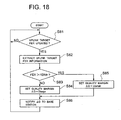
- FIG. 18 shows a flowchart of a process performed by the communication controller 91 shown in FIG. 17 .
- the process performed by the communication controller 91 according to the seventh embodiment will be described with reference to FIGS. 1 , 2 , 17 , and 18 .
- the uplink target FER information extracting module 911 of the communication controller 91 extract information about the target FER (step S82 in FIG. 18 ) and notifies it to the reception quality threshold setting module 912.
- the reception quality threshold setting module 912 sets the offset ⁇ D to ⁇ Dlarge (step S84 in FIG. 18 ). If the target FER provided from the uplink target FER information extracting module 911 is higher than the predetermined threshold FERth (step S83 in FIG. 18 ), the reception quality threshold setting module 912 sets the offset ⁇ D to ⁇ Dsmall (step S85 in FIG. 18 ).
- ⁇ Dsmall ⁇ ⁇ Dlarge is set to a predetermined threshold FERth.
- the offset ⁇ D set by the reception quality threshold setting module 912 is multiplexed and notified with a signal to be outputted to the base station 1-1, 1-2, 1-3 (step S86 in FIG. 18 ).
- the quality threshold which is determined as an offset ⁇ D to the target SIR, is set high so that the CW reception quality is determined to be degraded only if it is significantly degraded compared with the target SIR, thereby decreasing the probability that the reception quality of a non-transmit cell becomes lower than the threshold and minimizing interference in the downlink due to transmission by the non-transmit cell.
- the quality threshold which is determined as an offset ⁇ D to the target SIR, is set to a low value so that a CW is determined to be degraded if its reception quality is lower than the target SIR by a certain degree, thereby reducing CW errors in the transmit cells and inhibiting downlink degradation.
- a quality threshold which is set as a relative value to the uplink target SIR can be controlled according to the target SIR to minimize degradation of and interference in the downlink and therefore the capacity of the downlink can be increased.
- the communication controller 91 including the uplink target FER information extracting module 911 and reception quality threshold setting module 912 is provided in the radio network controller, the communication controller 91 may be provided in each base station 1-1, 1-2, 1-3.
- FIG. 19 is a block diagram showing a configuration of a radio network controller according to an eighth embodiment of the present invention.
- the configuration of the radio network controller according to the eighth embodiment of the present invention shown in FIG. 19 is the same as that of the radio network controller according to the first embodiment shown in FIG. 3 , except that a communication controller 101 including a CW count information extracting module 1011 and a reception quality threshold setting module 1012 is provided.
- the same components as those of the mobile communication system of the first embodiment are labeled with the same reference numbers. Operations of the same components as those in the first embodiment are also the same.
- the system configuration of the eighth embodiment of the present invention is the same as that of the cellular system according to the first embodiment shown in FIG. 1 .
- the configuration of a base station is the same as that of the base station 1-1, 1-2, 1-3 according to the first embodiment shown in FIG. 2 .
- the CW count information extracting module 1011 extracts information about the number of candidate CWs that can be transmitted by an mobile station 2-1, 2-2, 2-3 over an uplink and notifies it to the reception quality threshold setting module 1012.
- the reception quality threshold setting module 1012 set the quality threshold Qth according to the number of candidate CWs that can be transmitted over the uplink that is notified by the CW count information extracting module 1011. The less the candidate CWs, the lower threshold Qth is set by the reception quality threshold setting module 1012.
- the set quality threshold Qth is multiplexed and notified with an output signal to be transmitted to each base station 1-1, 1-2, and 1-3.
- FIG. 20 shows a flowchart of a process performed by the communication controller 101 shown in FIG. 19 .
- the process performed by the communication controller 101 according to the eighth embodiment of the present invention will be described with reference to FIGS. 1 , 2 , 19 , and 20 .
- the CW count information extracting module 1011 of the communication controller 101 extracts information about the candidate CW count (step S92 in FIG. 20 ) and notifies the information to the reception quality threshold setting module 1012.
- the reception quality threshold setting module 1012 sets the quality threshold Qth to Qlow (step S94 in FIG. 20 ).
- the reception quality threshold setting module 1012 sets the quality threshold Qth to Qhigh (step S95 in FIG. 20 ).
- Qlow ⁇ Qhigh.
- the quality threshold Qth set by the reception quality threshold setting module 1012 is multiplexed and notified with a signal to be outputted to the base station 1-1, 1-2, 1-3 (step S96 in FIG. 20 ).
- the quality threshold Qth is set to a low value to reduce interference which would be caused by transmission over the downlink made by a non-transmit base station in which the CW quality becomes lower than the quality threshold Qth.
- the number of candidate CWs that can be transmitted by a mobile station 2-1, 2-2, 2-3 over the uplink is large and therefore the CW reception quality is high and the probability of occurrence of CW determination errors is high
- the quality threshold Qth is set high to reduce CW errors in the transmit cell and inhibit degradation of the downlink.
- downlink degradation and interference can be minimized according to the number of candidate CWs that can be transmitted over the uplink and therefore the capacity of the downlink can be increased.
- the communication controller 101 including the CW count information extracting module 1011 and reception quality threshold setting module 1012 is provided in the radio network controller in the present embodiment, the communication controller 101 may be provided in each base station 1-1, 1-2, 1-3.
- each of the base stations 1-1, 1-2, and 1-3 in the first to eighth embodiments of the present invention makes transmission to three cells
- the number of cells to which each base station 1-1, 1-2, 1-3 makes transmission may be one, or others except for the three cells.
- the quality threshold Qth may be controlled by any combination of the first to eighth embodiments of the present invention.
- the quality threshold Qth for the reception quality of a CW which specifies a transmit cell to which a mobile station make transmission over an uplink is controlled according to propagation circumstances and communication conditions, as described above.
- the quality threshold Qth were high all the time, interference from a non-transmit cell would increase. If the quality threshold Qth were low all the time, the CW error rate in a transmit cell would increase to cause degradation of the downlink.
- a high quality threshold Qth can be set to decrease CW reception errors in the transmit cell. Otherwise, a low quality threshold Qth can be set to minimize transmissions and therefore interference by non-transmit cells.
- the capacity of the downlink can be increased according to the present invention.
- the present invention has the advantage the capacity of a downlink can be increased by changing the quality threshold according to propagation circumstances between a base station and a mobile station in a mobile communication system including base stations that transmit a common pilot signal with predetermined power to one or more cells and mobile stations that establish links to the base stations in one or more cells and measure the reception quality of the common pilot signal transmitted from the base stations.
Landscapes
- Engineering & Computer Science (AREA)
- Quality & Reliability (AREA)
- Computer Networks & Wireless Communication (AREA)
- Signal Processing (AREA)
- Mobile Radio Communication Systems (AREA)
- Radio Relay Systems (AREA)
Claims (31)
- Ein Verfahren zum Setzen eines Qualitätsschwellwerts, mit dem die Qualität eines Signals, das eine Übertragungszelle spezifiziert, verglichen wird, für ein mobiles Kommunikationssystem, das eine Basisstation (1-1, 1-2, 1-3) einschließt, die ein gemeinsames Pilotsignal unter Verwendung einer vorbestimmten Leistung an eine oder mehrere Zellen (201, ..., 208) überträgt und eine Mobilstation (2-1, 2-2, 2-3), die einen Link zu der Basisstation in der einen oder mehreren Zellen aufbaut und zum Messen der Empfangsqualität des gemeinsamen Pilotsignals, das von den Basisstationen übertragen wird, aufweisend den Schritt:Ändern des Qualitätsschwellwerts gemäß den Ausbreitungsumständen zwischen der Basisstation und der Mobilstation.
- Das Verfahren zum Setzen des Qualitätsschwellwerts nach Anspruch 1, verwendet mit einem Übertragungsleistungssteuerverfahren, bei dem die Mobilstation (2-1, 2-2, 2-3) eine oder mehrere Übertragungszellen aus den Zellen (201, ..., 208) auswählt, mit denen die Mobilstation einen Link basierend auf dem Ergebnis der Messung der Empfangsqualität des gemeinsamen Pilotsignals aufgebaut hat, und ein Signal zum Spezifizieren einer Übertragungszelle zum Spezifizieren der Übertragungszelle über einen Uplink überträgt, und
wobei die Basisstation (1-1, 1-2, 1-3), zu der der Uplink aufgebaut wird, die Empfangsqualität des Signals zur Spezifizierung der Übertragungszelle misst, das die Basisstation empfangen hat und eine Übertragung über einen Downlink durchführt, wenn die Empfangsqualität größer ist als der vorbestimmte Qualitätsschwellwert, und eine Zelle, zu der die Basisstation eine Übertragung durchführt, als Übertragungszelle durch die Übertragungszellen-Spezifizierungssignale spezifiziert wird, oder zumindest einen Teil der Übertragung über den Downlink stoppt, wenn die Empfangsqualität größer ist als der vorbestimmte Qualitätsschwellwert ist und die Zelle, zu der die Basisstation die Übertragung durchführt, nicht als Übertragungszelle durch das Übertragungszellen-Spezifizierungssignal spezifiert wird, oder eine Übertragung über den Downlink durchführt, falls die Empfangsqualität geringer ist als der vorbestimmte Qualitätsschwellwert. - Das Verfahren zum Setzen eines Qualitätsschwellwerts nach Anspruch 2, wobei der Qualitätsschwellwert in der Basisstation (1-1, 1-2, 1-3), zu der der Link aufgebaut wird, gemäß der Reisegeschwindigkeit der Mobilstation geändert wird.
- Das Verfahren zum Setzen eines Qualitätsschwellwerts nach Anspruch 2, wobei der Qualitätsschwellwert in der Basisstation (1-1, 1-2, 1-3), zu der der Link aufgebaut wird, verändert wird gemäß der Länge des Übertragungszellen-Spezifierungssignals, das über den Uplink übertragen wird.
- Das Verfahren zum Setzen eines Qualitätsschwellwerts nach Anspruch 2, wobei eine Fehlerkorrektur-Codierung auf das Übertragungszellen-Spezifierungssignal angewendet wird und der Qualitätsschwellwert in der Basisstation (1-1, 1-2, 1-3), zu der der Link aufgebaut wird, geändert wird gemäß der Redundanz der Fehlerkorrektur in dem Übertragungszellen-Spezifierungssignal.
- Das Verfahren zum Setzen eines Qualitätsschwellwerts nach Anspruch 2, wobei die Anzahl von Übertragungsbits des Übertragungszellen-Spezifierungssignals pro Zeiteinheit fest ist und der Qualitätsschwellwert in der Basisstation (1-1, 1-2, 1-3), mit der der Link aufgebaut wird, geändert wird entsprechend der Länge einer Zeitdauer, während derer das Übertragungszellen-Spezifizierungssignal übertragen wird.
- Das Verfahren zum Setzen eines Qualitätsschwellwerts nach Anspruch 2, wobei die Zeitdauer, während derer das Übertragungszellen-Spezifizierungssignal übertragen wird, fest ist und der Qualitätsschwellwert in der Basisstation (1-1, 1-2, 1-3), mit der der Link aufgebaut wird, verändert wird gemäß der Anzahl von Übertragungsbits des Übertragungszellen-Spezifizierungssignals per Zeiteinheit.
- Das Verfahren zum Setzen eines Qualitätsschwellwerts nach Anspruch 2, wobei das Übertragungszellen-Spezifizierungssignal ein Bitstrom ist, der einem Zellenidentifizierer entspricht, der jeder Zelle zugewiesen ist, und
der Qualitätsschwellwert in der Basisstation (1-1, 1-2, 1-3), mit der der Link aufgebaut wird, geändert wird gemäß der Anzahl von Bits in dem Bitstrom, was ein Kandidatenkriterium zum Evaluieren des Übertragungs-Spezifizierungssignals ist. - Das Verfahren zum Setzen eines Qualitätsschwellwerts nach Anspruch 2, wobei der Qualitätsschwellwert in der Basisstation (1-1, 1-2, 1-3), mit der der Link aufgebaut wird, geändert wird gemäß der Zielqualität des Downlink.
- Das Verfahren zum Setzen eines Qualitätsschwellwerts nach Anspruch 2, verwendet mit einem Verfahren zum Steuern einer Übertragungsleistung, wobei der Qualitätsschwellwert Oth gesetzt wird gemäß einer Gleichung

basierend auf einer Marge ΔD für eine Zielqualität-SIR des Uplink,
wobei die Marge ΔD zum Ermitteln des Qualitätsschwellwerts geändert wird gemäß der Zielqualität-SIR des Uplink. - Das Verfahren zum Setzen eines Qualitätsschwellwerts nach Anspruch 2, wobei der Qualitätsschwellwert in der Basisstation (1-1, 1-2, 1-3), mit der der Link aufgebaut wird, geändert wird gemäß der Anzahl von Handover-Zellen, zu denen die Basisstation eine Übertragung durchführt.
- Das Verfahren zum Setzen eines Qualitätsschwellwerts nach Anspruch 2, verwendet mit einem Übertragungsleistungssteuerverfahren, bei dem eine Zelle, die die höchste Empfangsqualität des gemeinsamen Pilotsignals liefert und eine Zelle, eine Empfangsqualität liefert, die sich von der Zelle in der Empfangsqualität um weniger als einen vorbestimmten Übertragungszellenauswahlschwellwert unterscheidet, als Übertragungszellen ausgewählt werden,
wobei der Qualitätsschwellwert in der Basisstation (1-1, 1-2, 1-3), zu der der Link aufgebaut wird, verändert wird entsprechend dem Übertragungszellenauswahlschwellwert. - Das Verfahren zum Setzen eines Qualitätsschwellwerts nach Anspruch 2, verwendet mit einem Übertragungsleistungssteuerverfahren, bei dem eine vorbestimmte Anzahl von Übertragungszellen ausgewählt wird in abnehmender Reihenfolge der Empfangsqualität des gemeinsamen Pilotsignals,
wobei der Qualitätsschwellwert in der Basisstation (1-1, 1-2, 1-3), zu der der Link aufgebaut wird, geändert wird gemäß der Anzahl von Übertragungszellen. - Das Verfahren zum Setzen eines Qualitätsschwellwerts nach Anspruch 10, wobei ein Kommunikationscontroller zum Setzen von zumindest einem aus dem Qualitätsschwellwert und der Marge ΔD zum Ermitteln des Qualitätsschwellwerts in einem Radionetzwerkcontroller bereitgestellt wird, mit dem die Basisstation, zu der der Link aufgebaut wird, verbunden ist.
- Das Verfahren zum Setzen eines Qualitätsschwellwerts nach Anspruch 10, wobei der Kommunikationscontroller (31) zum Setzen von zumindest einem aus dem Qualitätsschwellwert und der Marge ΔD zum Ermitteln des Qualitätsschwellwerts bereitgestellt wird und jeder der Basisstationen (1-1, 1-2, 1-3) zugeordnet wird.
- Ein Kommunikationscontroller (31) zur Verwendung in einem mobilen Kommunikationssystem einschließend eine Basisstation (1-1, 1-2, 1-3), die ein gemeinsames Pilotsignal unter Verwendung einer vorbestimmten Leistung zu einer oder mehreren Zellen (201, ..., 208) überträgt und eine mobile Station (2-1, 2-2, 2-3), die einen Link zu der Basisstation in der einen oder mehreren Zellen aufbaut und die Empfangsqualität des gemeinsamen Pilotsignals, das von den Basisstationen übertragen wird, misst, wobei der Kommunikationscontroller die Basisstation steuert, wobei der Kommunikationscontroller aufweist:Eine Einrichtung zum Verändern des Qualitätsschwellwerts mit dem die Qualität eines eine Übertragungszelle spezifizierenden Signals verglichen wird gemäß den Ausbreitungsumständen zwischen der Basisstation und der mobilen Station.
- Der Kommunikationscontroller nach Anspruch 16, verwendet mit einem Übertragungsleistungssteuerverfahren, bei dem die mobile Station (2-1, 2-2, 2-3) eine oder mehrere Übertragungszellen aus Zellen auswählt, mit denen die Mobilstation Links basierend auf dem Ergebnis der Messung der Empfangsqualität des gemeinsamen Pilotsignals aufgebaut hat und ein Übertragungszellen-Spezifizierungssignal zur Spezifizierung der Übertragungszelle über einen Uplink überträgt; und
wobei die Basisstation (1-1, 1-2, 1-3) mit der der Link aufgebaut wird, die Empfangsqualität des Übertragungszellen-Spezifizierungssignals misst, das die Basisstation empfangen hat, und eine Übertragung über einen Downlink durchführt, wenn die Empfangsqualität größer ist als der vorbestimmte Qualitätsschwellwert, und wobei eine Zelle, zu der die Basisstation eine Übertragung durchführt, als Übertragungszelle spezifiziert wird durch das Übertragungszellen-Spezifizierungssignal, oder zumindest einen Teil der Übertragung über den Downlink stoppt, wenn die Empfangsqualität größer ist als der vorbestimmte Qualitätsschwellwert und die Zelle, mit der die Basisstation eine Übertragung durchführt, nicht als Übertragungszelle durch das Übertragungszellen-Spezifizierungssignal spezifiziert wird, oder eine Übertragung über den Downlink durchführt, wenn die Empfangsqualität geringer ist als der vorbestimmte Qualitätsschwellwert. - Der Kommunikationscontroller nach Anspruch 17, wobei der Qualitätsschwellwert in der Basisstation (1-1, 1-2, 1-3), mit der der Link aufgebaut wird, gesteuert wird entsprechend der Reisegeschwindigkeit der Mobilstation.
- Der Kommunikationscontroller nach Anspruch 17, wobei der Qualitätsschwellwert in der Basisstation (1-1, 1-2, 1-3), mit der der Link aufgebaut wird, gesteuert wird gemäß der Länge des Übertragungszellen-Spezifizierungssignals, das über den Uplink übertragen wird.
- Der Kommunikationscontroller nach Anspruch 17, wobei eine Fehlerkorrekturcodierung angewendet wird auf das Übertragungszellen-Spezifizierungssignal und der Qualitätsschwellwert in der Basisstation (1-1, 1-2, 1-3), mit der der Link aufgebaut wird, gesteuert wird gemäß der Redundanz der Fehlerkorrektur in dem Übertragungszellen-Spezifizierungssignal.
- Der Kommunikationscontroller nach Anspruch 17, wobei die Anzahl von Übertragungsbits des Übertragungszellen-Spezifizierungssignals pro Zeiteinheit fest ist und der Qualitätsschwellwert in der Basisstation (1-1, 1-2, 1-3), mit der der Link aufgebaut wird, gesteuert wird gemäß der Länge einer Zeitdauer, während derer das Übertragungszellen-Spezifizierungssignal übertragen wird.
- Der Kommunikationscontroller nach Anspruch 17, wobei die Zeitdauer, während derer das Übertragungszellen-Spezifizierungssignal übertragen wird, fest ist und der Qualitätsschwellwert in der Basisstation (1-1, 1-2, 1-3), mit der der Link aufgebaut wird, gesteuert wird gemäß der Anzahl von Übertragungsbits des Übertragungszellen-Spezifizierungssignals pro Zeiteinheit.
- Der Kommunikationscontroller nach Anspruch 17, wobei das Übertragungszellen-Spezifizierungssignal ein Bitstrom ist, der einem Zellenidentifizierer, der jeder Zelle zugewiesen ist, entspricht, und
der Qualitätsschwellwert in der Basisstation (1-1, 1-2, 1-3), mit der der Link aufgebaut wird, gesteuert wird gemäß der Anzahl von Bits in dem Bitstrom, der ein Kandidatenkriterium zur Evaluierung des Übertragungszellen-Spezifizierungssignals ist. - Der Kommunikationscontroller nach Anspruch 17, wobei der Qualitätsschwellwert in der Basisstation (1-1, 1-2, 1-3), mit der der Link aufgebaut wird, gesteuert wird gemäß der Zielqualität des Downlinks.
- Der Kommunikationscontroller nach Anspruch 17, wobei der Qualitätsschwellwert Oth bestimmt wird gemäß einer Gleichung

basierend auf einer Marge ΔD für eine Zielqualität-SIR des Uplinks und
die Marge ΔD zum Ermitteln des Qualitätsschwellwerts in der Basisstation (1-1, 1-2, 1-3), mit der der Link aufgebaut wird, gesteuert wird gemäß der Zielqualität-SIR des Uplinks. - Der Kommunikationscontroller nach Anspruch 17, wobei der Qualitätsschwellwert in der Basisstation (1-1, 1-2, 1-3), mit der der Link aufgebaut wird, gesteuert wird gemäß der Anzahl von Handover-Zellen, zu der die Basisstation eine Übertragung durchführt.
- Der Kommunikationscontroller nach Anspruch 17, wobei eine Zelle, die die höchste Empfangsqualität des gemeinsamen Pilotsignals liefert und eine Zelle, die eine Empfangsqualität liefert, die sich von der Zelle in der Empfangsqualität um weniger als einen vorbestimmten Übertragungszellenauswahlschwellwert unterscheidet, als Übertragungszellen ausgewählt werden,
wobei der Qualitätsschwellwert in der Basisstation (1-1, 1-2, 1-3), mit der der Link aufgebaut wird, gesteuert wird gemäß dem Übertragungszellenauswahlschwellwert. - Der Kommunikationscontroller nach Anspruch 17, wobei eine vorbestimmte Anzahl von Übertragungszellen ausgewählt wird, in absteigender Reihenfolge der Empfangsqualität des gemeinsamen Pilotsignals,
wobei der Qualitätsschwellwert in der Basisstation (1-1, 1-2, 1-3), mit der der Link aufgebaut wird, gesteuert wird gemäß der Anzahl von Übertragungszellen. - Der Kommunikationscontroller nach Anspruch 17, wobei je größer die Anzahl der Übertragungszellen, desto niedriger der Qualitätsschwellwert gesetzt wird.
- Der Kommunikationscontroller nach Anspruch 16, welcher in einem Radionetzwerkcontroller bereitgestellt wird, mit dem die Basisstation die Verbindung aufbaut.
- Der Kommunikationscontroller nach Anspruch 16, der jeder der Basisstationen (1-1, 1-2, 1-3) zugeordnet ist.
Priority Applications (1)
| Application Number | Priority Date | Filing Date | Title |
|---|---|---|---|
| EP20090175908 EP2151929A3 (de) | 2002-02-12 | 2003-02-11 | Qualitätspegeleinstellungsverfahren |
Applications Claiming Priority (2)
| Application Number | Priority Date | Filing Date | Title |
|---|---|---|---|
| JP2002033296A JP4147780B2 (ja) | 2002-02-12 | 2002-02-12 | 品質しきい値設定方法及びそれを用いた通信制御装置 |
| JP2002033296 | 2002-02-12 |
Related Child Applications (2)
| Application Number | Title | Priority Date | Filing Date |
|---|---|---|---|
| EP20090175908 Division EP2151929A3 (de) | 2002-02-12 | 2003-02-11 | Qualitätspegeleinstellungsverfahren |
| EP09175908.4 Division-Into | 2009-11-13 |
Publications (3)
| Publication Number | Publication Date |
|---|---|
| EP1335502A2 EP1335502A2 (de) | 2003-08-13 |
| EP1335502A3 EP1335502A3 (de) | 2005-03-02 |
| EP1335502B1 true EP1335502B1 (de) | 2011-04-13 |
Family
ID=27606556
Family Applications (2)
| Application Number | Title | Priority Date | Filing Date |
|---|---|---|---|
| EP20030002669 Expired - Lifetime EP1335502B1 (de) | 2002-02-12 | 2003-02-11 | Qualitätspegeleinstellungsverfahren |
| EP20090175908 Withdrawn EP2151929A3 (de) | 2002-02-12 | 2003-02-11 | Qualitätspegeleinstellungsverfahren |
Family Applications After (1)
| Application Number | Title | Priority Date | Filing Date |
|---|---|---|---|
| EP20090175908 Withdrawn EP2151929A3 (de) | 2002-02-12 | 2003-02-11 | Qualitätspegeleinstellungsverfahren |
Country Status (5)
| Country | Link |
|---|---|
| US (1) | US20030153272A1 (de) |
| EP (2) | EP1335502B1 (de) |
| JP (1) | JP4147780B2 (de) |
| CN (1) | CN1260901C (de) |
| DE (1) | DE60336693D1 (de) |
Families Citing this family (24)
| Publication number | Priority date | Publication date | Assignee | Title |
|---|---|---|---|---|
| US7003310B1 (en) * | 2001-09-28 | 2006-02-21 | Arraycomm Llc. | Coupled uplink/downlink power control and spatial processing with adaptive antenna arrays |
| JP4084683B2 (ja) * | 2003-03-04 | 2008-04-30 | 株式会社エヌ・ティ・ティ・ドコモ | 移動通信システム、無線制御装置、基地局及び送信電力制御方法 |
| JPWO2005011152A1 (ja) * | 2003-07-25 | 2006-09-14 | 富士通株式会社 | 伝送品質計測装置、チャネル制御装置および無線基地局 |
| GB0326365D0 (en) | 2003-11-12 | 2003-12-17 | Koninkl Philips Electronics Nv | A radio communication system,a method of operating a communication system,and a mobile station |
| CN100444684C (zh) * | 2004-08-04 | 2008-12-17 | 中兴通讯股份有限公司 | 码分多址系统随机接入前导检测动态门限方法 |
| JP4559240B2 (ja) | 2005-01-13 | 2010-10-06 | 株式会社エヌ・ティ・ティ・ドコモ | 移動通信システム、無線基地局、無線回線制御局及び電力制御方法 |
| JP2007013446A (ja) * | 2005-06-29 | 2007-01-18 | Nec Electronics Corp | 移動端末装置および移動端末装置の動作制御方法 |
| US8731562B2 (en) * | 2005-08-30 | 2014-05-20 | Telefonaktiebolaget L M Ericsson (Publ) | Detection of control messages for HSDPA |
| US7852810B1 (en) | 2007-01-03 | 2010-12-14 | Sprint Spectrum L.P. | Dynamic adjustment of forward-link frame-error-rate (FFER) target |
| US7813323B1 (en) | 2007-06-13 | 2010-10-12 | Sprint Spectrum L.P. | Dynamic adjustment of reverse-link frame-error-rate (RFER) target based on reverse-link RF conditions |
| US8675743B2 (en) | 2007-08-03 | 2014-03-18 | Apple Inc. | Feedback scheduling to reduce feedback rates in MIMO systems |
| US8909279B2 (en) | 2007-08-10 | 2014-12-09 | Qualcomm Incorporated | Adaptation of transmit power for neighboring nodes |
| EP2083587A1 (de) * | 2008-01-25 | 2009-07-29 | British Telecommunications public limited company | Weiterreichungssteuerung |
| US7978623B1 (en) | 2008-03-22 | 2011-07-12 | Freescale Semiconductor, Inc. | Channel rank updates in multiple-input multiple-output communication systems |
| US8107988B1 (en) | 2008-07-25 | 2012-01-31 | Sprint Spectrum L.P. | Conducting power control based on reverse-link RF conditions |
| JP5172562B2 (ja) * | 2008-09-22 | 2013-03-27 | 株式会社エヌ・ティ・ティ・ドコモ | 移動局及び移動通信方法 |
| US8477686B1 (en) | 2009-09-10 | 2013-07-02 | Sprint Spectrum L.P. | Automatic increase of target frame error rate for duration based on call drop timer |
| JP5189111B2 (ja) * | 2010-01-07 | 2013-04-24 | 株式会社エヌ・ティ・ティ・ドコモ | 無線基地局装置、無線通信システム及び無線通信方法 |
| US8537700B1 (en) | 2010-04-19 | 2013-09-17 | Sprint Spectrum L.P. | Identifying and selectively controlling reverse-noise contribution on a per-access-terminal basis |
| US8290532B1 (en) | 2010-04-19 | 2012-10-16 | Sprint Spectrum L.P. | Selectively conducting reverse-link power control and call admission control |
| JP6497726B2 (ja) * | 2014-03-14 | 2019-04-10 | シャープ株式会社 | 端末、基地局、通信システム、通信方法、およびプログラム |
| JP6165201B2 (ja) * | 2015-08-05 | 2017-07-19 | 株式会社Nttドコモ | 無線基地局、ユーザ端末及び無線通信方法 |
| CN112105084B (zh) * | 2019-06-18 | 2025-03-21 | 上海朗帛通信技术有限公司 | 一种被用于无线通信的节点中的方法和装置 |
| JP7596200B2 (ja) * | 2021-03-30 | 2024-12-09 | 本田技研工業株式会社 | 情報処理装置、移動体、情報処理方法、及びプログラム |
Family Cites Families (14)
| Publication number | Priority date | Publication date | Assignee | Title |
|---|---|---|---|---|
| JP2911090B2 (ja) * | 1993-09-29 | 1999-06-23 | エヌ・ティ・ティ移動通信網株式会社 | 移動通信の基地局装置及び移動局装置 |
| US6137784A (en) * | 1995-10-18 | 2000-10-24 | Sc-Wireless Inc. | Method and apparatus for wireless communication employing control for confidence metric bandwidth reduction |
| US5930706A (en) * | 1995-11-29 | 1999-07-27 | Ericsson Inc. | Detecting messages transmitted over a communications channel such as a paging channel |
| JP2991185B2 (ja) | 1997-06-09 | 1999-12-20 | 日本電気株式会社 | セルラ通信システム、及びそれに用いられる移動機と基地局 |
| US6141555A (en) * | 1997-06-09 | 2000-10-31 | Nec Corporation | Cellular communication system, and mobile and base stations used in the same |
| US6173162B1 (en) * | 1997-06-16 | 2001-01-09 | Telefonaktiebolaget Lm Ericsson (Publ) | Multiple code channel power control in a radio communication system |
| US5946346A (en) * | 1997-10-07 | 1999-08-31 | Motorola, Inc. | Method and system for generating a power control command in a wireless communication system |
| JP3147850B2 (ja) * | 1998-03-26 | 2001-03-19 | 日本電気株式会社 | 移動通信システム及びその通信制御方法並びにそれに使用する基地局及び移動局 |
| US6298242B1 (en) * | 1999-07-22 | 2001-10-02 | Qualcomm Inc. | Method and apparatus for reducing frame error rate through signal power adjustment |
| JP3365379B2 (ja) * | 1999-12-13 | 2003-01-08 | 日本電気株式会社 | 基地局選択型送信電力制御方法及び基地局装置 |
| GB2357398B (en) * | 1999-12-16 | 2003-11-12 | Ericsson Telefon Ab L M | Telecommunications network |
| JP3480710B2 (ja) * | 2000-03-28 | 2003-12-22 | 松下電器産業株式会社 | 送信電力制御装置及び送信電力制御方法 |
| JP4453168B2 (ja) * | 2000-06-23 | 2010-04-21 | 日本電気株式会社 | 移動通信制御方法、セルラシステム、移動局、基地局及び基地局制御装置 |
| JP3473555B2 (ja) * | 2000-06-30 | 2003-12-08 | 日本電気株式会社 | 送信電力制御方式、制御方法及び基地局、制御局並びに記録媒体 |
-
2002
- 2002-02-12 JP JP2002033296A patent/JP4147780B2/ja not_active Expired - Fee Related
-
2003
- 2003-02-11 EP EP20030002669 patent/EP1335502B1/de not_active Expired - Lifetime
- 2003-02-11 US US10/361,622 patent/US20030153272A1/en not_active Abandoned
- 2003-02-11 DE DE60336693T patent/DE60336693D1/de not_active Expired - Lifetime
- 2003-02-11 EP EP20090175908 patent/EP2151929A3/de not_active Withdrawn
- 2003-02-12 CN CNB031206751A patent/CN1260901C/zh not_active Expired - Fee Related
Also Published As
| Publication number | Publication date |
|---|---|
| EP1335502A2 (de) | 2003-08-13 |
| CN1260901C (zh) | 2006-06-21 |
| CN1440151A (zh) | 2003-09-03 |
| EP1335502A3 (de) | 2005-03-02 |
| JP2003234697A (ja) | 2003-08-22 |
| US20030153272A1 (en) | 2003-08-14 |
| JP4147780B2 (ja) | 2008-09-10 |
| DE60336693D1 (de) | 2011-05-26 |
| EP2151929A3 (de) | 2014-09-10 |
| EP2151929A2 (de) | 2010-02-10 |
Similar Documents
| Publication | Publication Date | Title |
|---|---|---|
| EP1335502B1 (de) | Qualitätspegeleinstellungsverfahren | |
| KR100424829B1 (ko) | 기지국 송신 제어 방법, 셀룰러 시스템 및 기지국 | |
| US7031712B2 (en) | Mobile communication control method and system and mobile station thereof | |
| JP4453168B2 (ja) | 移動通信制御方法、セルラシステム、移動局、基地局及び基地局制御装置 | |
| AU2007202316B2 (en) | Method for soft and softer handover in time division duplex code division multiple access (TDD-CDMA) networks | |
| US8428636B2 (en) | Radio communication system for selecting a subset of available primary stations | |
| EP1414261B1 (de) | Zellulares System | |
| US20040072565A1 (en) | Best-cell amendment method for amending hysteresis margin according to the degree of congestion | |
| US7417975B2 (en) | Cellular system and base station specification method in CDMA mode | |
| KR20010021080A (ko) | 전송 전력 레벨의 제어 방법 | |
| US20060166665A1 (en) | Radio communication system | |
| US7146168B2 (en) | Method and system for providing a downlink connection in a cellular network | |
| JP2008245315A (ja) | 通信制御方法及びそれを用いた通信制御装置 | |
| JP2005277610A (ja) | 送信電力制御システム、基地局及びそれらに用いる送信電力制御方法 |
Legal Events
| Date | Code | Title | Description |
|---|---|---|---|
| PUAI | Public reference made under article 153(3) epc to a published international application that has entered the european phase |
Free format text: ORIGINAL CODE: 0009012 |
|
| AK | Designated contracting states |
Designated state(s): AT BE BG CH CY CZ DE DK EE ES FI FR GB GR HU IE IT LI LU MC NL PT SE SI SK TR |
|
| AX | Request for extension of the european patent |
Extension state: AL LT LV MK RO |
|
| PUAL | Search report despatched |
Free format text: ORIGINAL CODE: 0009013 |
|
| AK | Designated contracting states |
Kind code of ref document: A3 Designated state(s): AT BE BG CH CY CZ DE DK EE ES FI FR GB GR HU IE IT LI LU MC NL PT SE SI SK TR |
|
| AX | Request for extension of the european patent |
Extension state: AL LT LV MK RO |
|
| RIC1 | Information provided on ipc code assigned before grant |
Ipc: 7H 04B 7/005 A Ipc: 7H 04Q 7/38 B |
|
| 17P | Request for examination filed |
Effective date: 20050720 |
|
| AKX | Designation fees paid |
Designated state(s): DE FR GB IT |
|
| 17Q | First examination report despatched |
Effective date: 20090130 |
|
| GRAP | Despatch of communication of intention to grant a patent |
Free format text: ORIGINAL CODE: EPIDOSNIGR1 |
|
| RIC1 | Information provided on ipc code assigned before grant |
Ipc: H04B 7/005 20060101AFI20100825BHEP Ipc: H04W 52/14 20090101ALI20100825BHEP |
|
| GRAS | Grant fee paid |
Free format text: ORIGINAL CODE: EPIDOSNIGR3 |
|
| GRAA | (expected) grant |
Free format text: ORIGINAL CODE: 0009210 |
|
| AK | Designated contracting states |
Kind code of ref document: B1 Designated state(s): DE FR GB IT |
|
| REG | Reference to a national code |
Ref country code: GB Ref legal event code: FG4D |
|
| REF | Corresponds to: |
Ref document number: 60336693 Country of ref document: DE Date of ref document: 20110526 Kind code of ref document: P |
|
| REG | Reference to a national code |
Ref country code: DE Ref legal event code: R096 Ref document number: 60336693 Country of ref document: DE Effective date: 20110526 |
|
| PLBE | No opposition filed within time limit |
Free format text: ORIGINAL CODE: 0009261 |
|
| STAA | Information on the status of an ep patent application or granted ep patent |
Free format text: STATUS: NO OPPOSITION FILED WITHIN TIME LIMIT |
|
| 26N | No opposition filed |
Effective date: 20120116 |
|
| REG | Reference to a national code |
Ref country code: DE Ref legal event code: R097 Ref document number: 60336693 Country of ref document: DE Effective date: 20120116 |
|
| REG | Reference to a national code |
Ref country code: FR Ref legal event code: PLFP Year of fee payment: 14 |
|
| REG | Reference to a national code |
Ref country code: FR Ref legal event code: PLFP Year of fee payment: 15 |
|
| PGFP | Annual fee paid to national office [announced via postgrant information from national office to epo] |
Ref country code: FR Payment date: 20170112 Year of fee payment: 15 Ref country code: DE Payment date: 20170207 Year of fee payment: 15 |
|
| PGFP | Annual fee paid to national office [announced via postgrant information from national office to epo] |
Ref country code: GB Payment date: 20170208 Year of fee payment: 15 |
|
| PGFP | Annual fee paid to national office [announced via postgrant information from national office to epo] |
Ref country code: IT Payment date: 20170221 Year of fee payment: 15 |
|
| REG | Reference to a national code |
Ref country code: DE Ref legal event code: R119 Ref document number: 60336693 Country of ref document: DE |
|
| GBPC | Gb: european patent ceased through non-payment of renewal fee |
Effective date: 20180211 |
|
| REG | Reference to a national code |
Ref country code: FR Ref legal event code: ST Effective date: 20181031 |
|
| PG25 | Lapsed in a contracting state [announced via postgrant information from national office to epo] |
Ref country code: DE Free format text: LAPSE BECAUSE OF NON-PAYMENT OF DUE FEES Effective date: 20180901 |
|
| PG25 | Lapsed in a contracting state [announced via postgrant information from national office to epo] |
Ref country code: IT Free format text: LAPSE BECAUSE OF NON-PAYMENT OF DUE FEES Effective date: 20180211 Ref country code: GB Free format text: LAPSE BECAUSE OF NON-PAYMENT OF DUE FEES Effective date: 20180211 Ref country code: FR Free format text: LAPSE BECAUSE OF NON-PAYMENT OF DUE FEES Effective date: 20180228 |