EP1335512A2 - Signalvorverarbeitung der überlagerten Signale in einem digitalen Modulationsschema mit überlagerten Signalen zur Verwendung von bestehenden Empfängern - Google Patents
Signalvorverarbeitung der überlagerten Signale in einem digitalen Modulationsschema mit überlagerten Signalen zur Verwendung von bestehenden Empfängern Download PDFInfo
- Publication number
- EP1335512A2 EP1335512A2 EP03002177A EP03002177A EP1335512A2 EP 1335512 A2 EP1335512 A2 EP 1335512A2 EP 03002177 A EP03002177 A EP 03002177A EP 03002177 A EP03002177 A EP 03002177A EP 1335512 A2 EP1335512 A2 EP 1335512A2
- Authority
- EP
- European Patent Office
- Prior art keywords
- signal
- layered
- phase
- quadrature
- upper layer
- Prior art date
- Legal status (The legal status is an assumption and is not a legal conclusion. Google has not performed a legal analysis and makes no representation as to the accuracy of the status listed.)
- Granted
Links
Images




Classifications
-
- H—ELECTRICITY
- H04—ELECTRIC COMMUNICATION TECHNIQUE
- H04H—BROADCAST COMMUNICATION
- H04H20/00—Arrangements for broadcast or for distribution combined with broadcast
- H04H20/28—Arrangements for simultaneous broadcast of plural pieces of information
- H04H20/30—Arrangements for simultaneous broadcast of plural pieces of information by a single channel
- H04H20/31—Arrangements for simultaneous broadcast of plural pieces of information by a single channel using in-band signals, e.g. subsonic or cue signal
-
- H—ELECTRICITY
- H04—ELECTRIC COMMUNICATION TECHNIQUE
- H04B—TRANSMISSION
- H04B7/00—Radio transmission systems, i.e. using radiation field
- H04B7/14—Relay systems
- H04B7/15—Active relay systems
- H04B7/185—Space-based or airborne stations; Stations for satellite systems
- H04B7/1851—Systems using a satellite or space-based relay
- H04B7/18515—Transmission equipment in satellites or space-based relays
-
- H—ELECTRICITY
- H04—ELECTRIC COMMUNICATION TECHNIQUE
- H04L—TRANSMISSION OF DIGITAL INFORMATION, e.g. TELEGRAPHIC COMMUNICATION
- H04L27/00—Modulated-carrier systems
- H04L27/32—Carrier systems characterised by combinations of two or more of the types covered by groups H04L27/02, H04L27/10, H04L27/18 or H04L27/26
- H04L27/34—Amplitude- and phase-modulated carrier systems, e.g. quadrature-amplitude modulated carrier systems
- H04L27/3488—Multiresolution systems
Definitions
- the present invention relates generally to systems for receiving digital signals, and in particular, to systems for receiving layered modulation in digital signals.
- the conventional method of increasing spectral capacity is to move to a higher-order modulation, such as from quadrature phase shift keying (QPSK) to eight phase shift keying (8PSK) or sixteen quadrature amplitude modulation (16QAM).
- QPSK quadrature phase shift keying
- 8PSK eight phase shift keying
- 16QAM sixteen quadrature amplitude modulation
- QPSK receivers cannot demodulate 8PSK or 16QAM signals.
- legacy customers with QPSK receivers must upgrade their receivers in order to continue to receive any signals transmitted with an 8PSK or 16QAM modulation.
- Layered modulation enables systems and methods of transmitting signals to accommodate enhanced and increased data throughput without requiring additional frequency bands.
- Systems using layered modulation can provide enhanced and increased throughput signals for new receivers while remaining compatible with legacy receivers.
- Newer layered modulation techniques (such as detailed in United States Patent Application No. XXXXX, filed XXXX, and entitled "LAYERED MODULATION FOR DIGITAL SIGNALS) also provide the unique advantage of allowing transmission signals to be upgraded from a source separate from the legacy transmitter.
- the layered signals can be asynchronous and/or non-coherent.
- receiver systems for layered signals have also been described, such as those found in United States Patent No. 4,039,961, which is incorporated by reference herein.
- receiver systems are based on analog circuits, synchronized by a voltage control oscillator.
- receiver systems are limited because they are designed to only receive coherent layered signals, i.e. signals that are synchronously produced.
- the present invention provides a flexible and expandable apparatus that can be implemented with high speed logic circuit technology capable of performing demodulator functions and processing of received layered modulation signals in real-time.
- the invention utilizes high speed digitization of the incoming signal to prepare it for further high-speed digital processing.
- the invention enables a receive system architecture wherein the incoming signal is split and separately directed to distinct integrated receiver/decoders (IRDs).
- IRDs integrated receiver/decoders
- the system facilitates compatibility with legacy IRDs.
- One legacy IRD can be used to receive the upper modulation layer as it would receive a conventional unlayered signal. In this IRD the lower modulation layer is ignored as noise.
- a second legacy IRD receives a signal that has been preprocessed to extract and convert the lower modulation signal to a legacy IRD compatible signal.
- An exemplary apparatus comprises a tuner for receiving a layered signal and producing a layered in-phase signal and a layered quadrature signal therefrom, an analog-to-digital converter for digitizing the layered in-phase signal and the layered quadrature signal, a processor for decoding the layered in-phase signal and the layered quadrature signal to produce a single layer in-phase signal and a single layer quadrature signal, a digital-to-analog encoder for converting the single layer in-phase signal and the single layer quadrature signal to a single layer in-phase analog signal and a single layer quadrature analog signal and a modulator for modulating the single layer in-phase analog signal and the single layer quadrature analog signal to produce a single layer signal.
- the layered signal is designed to be compatible with a legacy receiver such that at least one signal layer is decodeable directly from the layered signal with the legacy receiver.
- the apparatus produces a single layer signal that is also decodeable with a legacy receiver.
- the processor can comprise a logic circuit. Decoding by the processor can start with match filtering the layered in-phase signal and the layered quadrature signal.
- the processor demodulates and decodes an upper layer signal from the layered in-phase signal and the layered quadrature signal.
- the processor further produces an ideal noise free upper layer signal including an ideal in-phase upper layer signal and an ideal quadrature upper layer signal from the decoded upper layer signal and subtracts the ideal in-phase upper layer signal and the ideal quadrature upper layer signal from the layered in-phase signal and the layered quadrature signal, respectively, to produce the single lower layer in-phase signal and the single lower layer quadrature signal.
- the layered in-phase signal and the layered quadrature signal are delayed to synchronize the subtraction.
- producing the ideal upper layer signal comprises signal processing the ideal in-phase upper layer signal and the ideal quadrature upper layer signal.
- Signal processing the ideal upper layer can include many elements, including pulse shaping the ideal in-phase upper layer signal and the ideal quadrature upper layer signal.
- Signal mapping to account for transmission distortions of the layered analog signal can also be applied to the ideal in-phase upper layer signal and the ideal quadrature upper layer signal.
- the ideal upper layer signal can also be processed by amplitude and phase matching with the layered signal to improve signal subtraction results.
- FIGS. 1A - 1C illustrate the relationship of signal layers in a layered modulation transmission
- FIGS. 2A - 2C illustrate a signal constellation of a second transmission layer over a first transmission layer non-coherently
- FIG. 3 is a block diagram for a typical transmission system for a receiver of the invention.
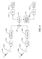
- FIG. 4 is a block diagram of a receiving architecture of the invention.
- FIG. 5 is a block diagram of a layered modulation decoder of the invention.
- FIG. 6 is a method of a layered modulation decoding according to the invention.
- the present invention provides for the reception of non-coherent legacy layered modulation signals using legacy receivers.
- the signal layers can be independently modulated and coded. Signal layers which are otherwise incompatible with the legacy receiver are preprocessed in a layered modulation decoder to convert them to a compatible format.
- all layers of the layered modulation signal can be received by splitting the incoming signal and directing it to different legacy receivers, preprocessing as necessary to extract the desired layer and present it in a compatible format.
- at least one layer of the signal is compatible with a legacy receiver without being preprocessed.
- FIGS. 1A - 1C and FIGS. 2A - 2C illustrate and QPSK signal format in a two-layer example.
- FIGS. 1A - 1C illustrate the basic relationship of signal layers in a layered modulation transmission.
- FIG. 1A illustrates a upper layer signal constellation 100 of a transmission signal showing the signal points or symbols 102.
- FIG. 1B illustrates the lower layer signal constellation of symbols 104 over the upper layer signal constellation 100 where the layers are coherent.
- FIG. 1C illustrates a lower signal layer 106 of a lower transmission layer over the upper layer constellation where the layers may be non-coherent.
- the lower layer 106 rotates about the upper layer constellation 102 due to the relative modulating frequencies of the two layers in a non-coherent transmission. Both the upper and lower layers rotate about the origin due to the upper layer modulation frequency as described by path 108.
- FIGS. 2A - 2C illustrate a signal constellation of a lower transmission layer over the upper transmission layer after upper layer demodulation.
- FIG. 2A shows the constellation 200 before the upper carrier recovery loop (CRL) and FIG. 2B shows the constellation 200 after CRL.
- the signal points of the lower layer are rings 202.
- FIG. 2C depicts a phase distribution of the received signal with respect to nodes 102.
- relative modulating frequencies cause the lower layer constellation to rotate around the nodes of the upper layer constellation. After the lower layer CRL this rotation is eliminated.
- the radius of the lower layer constellation is determined by its power level.
- the thickness of the rings 202 is determined by the carrier to noise ratio (CNR) of the lower layer.
- CNR carrier to noise ratio
- FIG. 3 is a block diagram for a typical system 300 of transmitting and receiving layered signals.
- Separate transmitters 316A, 316B as may be located on any suitable platform, such as satellites 306A, 306B, are used to non-coherently transmit different layers of a signal of the present invention. It is noted that the transmitters may also be positioned on the same platform.
- Uplink signals are typically transmitted to each satellite 306A, 306B from one or more transmit stations 304 via an antenna 302.
- the layered signals 308A, 308B are received at receiver antennas 312, 320 (which can alternately be a single antenna), such as satellite dishes, each with a low noise block (LNB) 310, 318 (which can likewise be a single LNB) where they are then coupled to legacy integrated receiver/decoders (IRDs) 322.
- LNB low noise block
- IRDs legacy integrated receiver/decoders
- One of the layered signals 308A can be distinguished and processed directly by the legacy IRD 322. Note that one satellite dish with one LNB can also be used to receive both the upper and lower layers.
- one legacy IRD 314 has the received layered signals 308A, 308B preprocessed in the layered modulation decoder 324 to separate and convert one of the layered signals 308B to a format compatible with the legacy IRDs 314, 322.
- antennas 312, 320 can each comprise more than one directional receiving dish to receive layered signals 308A, 308B from separate satellites as will be detailed in the receiver system described hereafter.
- any composite signal, including new additional signal layers will be backwards compatible with legacy receivers which will disregard the new signal layers.
- the combined signal and noise level for the lower layer must be at or below the allowed noise floor for the upper layer.
- Alternate receiver systems employing the invention described here can be constructed to decode signals having more than two signal layers.
- FIG. 4 is a block diagram of a receiving architecture for demonstrating the invention method.
- Emulated layered signals 400A, 400B are received by receiving dishes 402A, 402B (which can alternately be combined in a single dish with a single LNB).
- the signals 400A, 400B can each be transmitted by distinct transmitters from a single or separate satellites, but they exist in interfering frequency bands, e.g. 12.5 GHz.
- the received layered signals 400A, 400B are then directed through respective low noise blocks (LNBs) 404A, 404B and attenuators 406A, 406B.
- the LNBs 404A, 404B convert each of the received layered signals 400A, 400B to an intermediate frequency range, e.g. 950-1450 MHz.
- the layered signals are combined at the summation block 408, with their relative power levels adjusted by the attenuators 406A, 406B.
- the details regarding the reception of the layered signal up to the summation block 408 are not critical to the operation of the invention and shown only as one example. Many designs are possible. For example, as previously mentioned, the same receiver dish can be used for both layered signals 400A, 400B. The result of two acceptably interfering layered signals on the same input is the only requirement.
- the combined layered signals 400A, 400B can then be split at splitter 410 to direct the layered signal to alternate legacy IRDs 412A, 412B.
- One of the legacy IRDs 412A demodulates and decodes the upper layer signal of the signals 400A, 400B and ignores the other as noise.
- the decoded upper layer signal is then delivered to a display 414A.
- the other legacy IRD 412B has the layered signals 400A, 400B preprocessed by a layered modulation decoder 416 such that the lower layer signal of the signals 400A, 400B is converted to a signal compatible with the other legacy IRD 412B (and the upper layer signal of the signals 400A, 400B is effectively filtered out).
- the converted lower layer signal is then demodulated and decoded by the other legacy IRD 412B and the result delivered to a display 414B.
- alternate architectures can employ a single display switched between signals from the separate IRDs 412A, 412B.
- FIG. 5 is a block diagram of a layered modulation decoder 416 of the invention.
- the layered modulation decoder 416 preprocesses an incoming layered signal to extract a lower layer signal and convert it to a signal that is decodable by a legacy receiver, as previously discussed.
- the incoming layered signal is upper tuned to convert it to a baseband in-phase (I) and quadrature (Q) signal by tuner 500.
- the separate signals can then be filtered by a low pass filter 502 in preparation for digitizing.
- the signals are then digitized at a high sampling rate and sufficient resolution by an analog-to-digital converter (ADC) 504.
- ADC analog-to-digital converter
- ADC 504 or separate ADCs can be used for the separate in-phase and quadrature signals.
- the digitized signals are then communicated to a processor 506.
- the processor 506 for extracting a lower layer signal can be implemented as a logic circuit.
- the entering digitized in-phase and quadrature signals can be first split into two paths that will become the upper layer and composite layered signals.
- the in-phase and quadrature signals can first be passed through a frequency acquisition loop 508.
- The can then be filtered through a finite impulse response (FIR) matched filter 510.
- FIR finite impulse response
- a demodulator 512 demodulates the signals, using carrier and timing recovery loops to produce demodulated layered in-phase and quadrature signals.
- the demodulated signals are then decoded by decoder 514 which can incorporate Viterbi decoding, deinterleaving and Reed-Solomon (RS) decoding functions as appropriate to accurately determine the upper layer symbols.
- the decoded upper layer symbols are then applied to an encoder 516 in order to produce an ideal upper layer signal (i.e. an upper layer signal transmitted without the noise and/or interference of the lower layer signal).
- the encoded signal emerges again as in-phase and quadrature signal components. A variety of signal processing techniques can be applied to these signals to produce the ideal upper layer.
- the ideal upper layer signal can be filtered through an FIR matched filter 518.
- Characteristics of the transmission e.g. amplifier nonlinearities, etc.
- signal maps 520 can be accounted for by signal maps 520, such as an amplitude modulation to amplitude modulation (AM/AM) map and/or an amplitude modulation to phase modulation map (AM/PM).
- AM/AM amplitude modulation to amplitude modulation
- AM/PM amplitude modulation to phase modulation map
- These signal maps 520 can be updated to account for changes in the transmission characteristics of the satellite.
- the signal maps 520 are applied 522 to the encoded signals to simulate downlink transmission of an upper layer signal.
- an additional FIR matched filter 526 can also be applied after accounting for transmission characteristics 522.
- an upper layer amplitude and phase matching function 528 driven by the demodulated layered signal and the ideal reconstructed upper layer signal, can also be used to generate matching coefficients.
- the matching coefficients are applied 524 to the reconstructed upper layer signal to ensure that it is appropriately scaled in magnitude and rotated in phase as compared to the layered signal, for maximum cancellation in the final signal subtraction.
- the ideal reconstructed in-phase and quadrature signals for the upper layer are subtracted from the layered in-phase and quadrature signals that are produced by the demodulator at a subtractor 538.
- a timing and phase compensation function 532 is applied to the second layered path entering the processor 506, using information from the demodulator 512.
- a fixed delay 534 can be applied to the second layered signal path to determine the appropriate delay to align the layered and ideal signals to generate matching coefficients 528.
- the delayed layered signal is split and in one path, an FIR matched filter 530 can be applied to it before generating matching coefficients 528.
- the second delayed layered signal path is delayed again 536 to align it appropriately with the ideal upper layer signal for subtraction 538.
- the results of the subtraction are the in-phase and quadrature signals of the lower layer.
- the in-phase and quadrature signals of the lower layer, output from the subtractor 538, are first converted to analog signals in an digital-to-analog converter (DAC) 540.
- DAC digital-to-analog converter
- the DAC essentially reverses the prior digitizing and therefore may use the same sampling rate and resolution.
- the analog form signals can be filtered by a low pass filter 542 and passed to a modulator 544 (e.g. a QPSK modulator) to produce the lower layer signal in a format for a legacy receiver to decode, as the output of the processor 416.
- a modulator 544 e.g. a QPSK modulator
- FIG. 6 describes a method of a layered modulation decoding according to the invention.
- a layered signal is received a layered in-phase signal and a layered quadrature signal are produced from it at block 600.
- the layered in-phase signal and the layered quadrature signal are digitized at block 602.
- the layered in-phase signal and the layered quadrature signal are decoded to produce a single layer in-phase signal and a single layer quadrature signal.
- the single layer in-phase signal and the single layer quadrature signal are converted to a single layer in-phase analog signal and a single layer quadrature analog signal.
- the single layer in-phase analog signal and the single layer quadrature analog signal are modulated to produce a single layer signal.
Landscapes
- Engineering & Computer Science (AREA)
- Signal Processing (AREA)
- Computer Networks & Wireless Communication (AREA)
- Physics & Mathematics (AREA)
- Astronomy & Astrophysics (AREA)
- Aviation & Aerospace Engineering (AREA)
- General Physics & Mathematics (AREA)
- Digital Transmission Methods That Use Modulated Carrier Waves (AREA)
Applications Claiming Priority (2)
| Application Number | Priority Date | Filing Date | Title |
|---|---|---|---|
| US10/068,039 US7245671B1 (en) | 2001-04-27 | 2002-02-05 | Preprocessing signal layers in a layered modulation digital signal system to use legacy receivers |
| US68039 | 2002-02-05 |
Publications (3)
| Publication Number | Publication Date |
|---|---|
| EP1335512A2 true EP1335512A2 (de) | 2003-08-13 |
| EP1335512A3 EP1335512A3 (de) | 2003-10-22 |
| EP1335512B1 EP1335512B1 (de) | 2007-02-28 |
Family
ID=27610524
Family Applications (1)
| Application Number | Title | Priority Date | Filing Date |
|---|---|---|---|
| EP03002177A Expired - Lifetime EP1335512B1 (de) | 2002-02-05 | 2003-02-03 | Signalvorverarbeitung der überlagerten Signale in einem digitalen Modulationsschema mit überlagerten Signalen zur Verwendung von bestehenden Empfängern |
Country Status (4)
| Country | Link |
|---|---|
| EP (1) | EP1335512B1 (de) |
| JP (1) | JP3668229B2 (de) |
| DE (1) | DE60312060T2 (de) |
| ES (1) | ES2282528T3 (de) |
Cited By (9)
| Publication number | Priority date | Publication date | Assignee | Title |
|---|---|---|---|---|
| EP1478146A1 (de) * | 2003-05-14 | 2004-11-17 | STMicroelectronics S.A. | Empfang zweier unkorrelierter, auf einem einzigen Kanal übertragender Signale |
| WO2004100479A1 (en) * | 2003-05-05 | 2004-11-18 | Thomson Licensing S.A. | Method and apparatus for synchronizing a multi-level modulation signal |
| EP1579706A4 (de) * | 2002-10-25 | 2008-02-13 | Directv Group Inc | Verfahren und vorrichtung zum anpassen von trägerleistungsanforderungen gemäss verfügbarkeit in geschichteten modulationssystemen |
| EP1561291A4 (de) * | 2002-10-25 | 2008-02-13 | Directv Group Inc | Amplituden- und phasenanpassung für den empfang überlagerter modulationssignale |
| EP1559253A4 (de) * | 2002-10-25 | 2008-02-13 | Direct Tv Group Inc | Maximierung von leistungs- und spektraleffizienzen für geschichtete und herkömmliche modulationen |
| US7907639B2 (en) | 2003-05-05 | 2011-03-15 | Thomson Licensing | Method and apparatus for synchronizing a multi-level modulation signal |
| US8170068B2 (en) | 2003-11-03 | 2012-05-01 | Qualcomm Incorporated | Method, apparatus, and system for data transmission and processing in a wireless communication environment |
| GB2488168A (en) * | 2011-02-18 | 2012-08-22 | Samsung Electronics Co Ltd | Additional signalling for Digital Video Broadcasting |
| US11362757B2 (en) | 2015-03-26 | 2022-06-14 | Sony Corporation | Apparatus including a transmission processing unit that generates transmission signal sequences of multiple power layers |
Families Citing this family (18)
| Publication number | Priority date | Publication date | Assignee | Title |
|---|---|---|---|---|
| US7583728B2 (en) | 2002-10-25 | 2009-09-01 | The Directv Group, Inc. | Equalizers for layered modulated and other signals |
| US7423987B2 (en) | 2001-04-27 | 2008-09-09 | The Directv Group, Inc. | Feeder link configurations to support layered modulation for digital signals |
| US7245671B1 (en) | 2001-04-27 | 2007-07-17 | The Directv Group, Inc. | Preprocessing signal layers in a layered modulation digital signal system to use legacy receivers |
| US7173981B1 (en) | 2001-04-27 | 2007-02-06 | The Directv Group, Inc. | Dual layer signal processing in a layered modulation digital signal system |
| US7502430B2 (en) | 2001-04-27 | 2009-03-10 | The Directv Group, Inc. | Coherent averaging for measuring traveling wave tube amplifier nonlinearity |
| US7822154B2 (en) | 2001-04-27 | 2010-10-26 | The Directv Group, Inc. | Signal, interference and noise power measurement |
| US7483505B2 (en) | 2001-04-27 | 2009-01-27 | The Directv Group, Inc. | Unblind equalizer architecture for digital communication systems |
| US7639759B2 (en) | 2001-04-27 | 2009-12-29 | The Directv Group, Inc. | Carrier to noise ratio estimations from a received signal |
| US7778365B2 (en) | 2001-04-27 | 2010-08-17 | The Directv Group, Inc. | Satellite TWTA on-line non-linearity measurement |
| US7471735B2 (en) | 2001-04-27 | 2008-12-30 | The Directv Group, Inc. | Maximizing power and spectral efficiencies for layered and conventional modulations |
| US7209524B2 (en) | 2001-04-27 | 2007-04-24 | The Directv Group, Inc. | Layered modulation for digital signals |
| WO2004004193A2 (en) | 2002-07-01 | 2004-01-08 | The Directv Group, Inc. | Improving hierarchical 8psk performance |
| TWI279113B (en) | 2002-07-03 | 2007-04-11 | Hughes Electronics Corp | Method and apparatus for layered modulation |
| US7463676B2 (en) | 2002-10-25 | 2008-12-09 | The Directv Group, Inc. | On-line phase noise measurement for layered modulation |
| US7474710B2 (en) | 2002-10-25 | 2009-01-06 | The Directv Group, Inc. | Amplitude and phase matching for layered modulation reception |
| US7529312B2 (en) | 2002-10-25 | 2009-05-05 | The Directv Group, Inc. | Layered modulation for terrestrial ATSC applications |
| ES2398213T3 (es) | 2002-10-25 | 2013-03-14 | The Directv Group, Inc. | Procesador de señal de modulación en capas de baja complejidad |
| JP4777440B2 (ja) * | 2006-02-01 | 2011-09-21 | エルジー エレクトロニクス インコーポレイティド | 無線通信システムにおける重畳変調を用いたデータ送受信方法 |
Family Cites Families (3)
| Publication number | Priority date | Publication date | Assignee | Title |
|---|---|---|---|---|
| US4992747A (en) * | 1988-08-16 | 1991-02-12 | Myers Glen A | Multiple reuse of an FM band |
| US5430770A (en) * | 1994-04-22 | 1995-07-04 | Rockwell International Corp. | Method and apparatus for composite signal separation and PSK/AM/FM demodulation |
| US5966412A (en) * | 1997-06-30 | 1999-10-12 | Thomson Consumer Electronics, Inc. | Apparatus and method for processing a Quadrature Amplitude Modulated (QAM) signal |
-
2003
- 2003-02-03 DE DE2003612060 patent/DE60312060T2/de not_active Expired - Lifetime
- 2003-02-03 ES ES03002177T patent/ES2282528T3/es not_active Expired - Lifetime
- 2003-02-03 EP EP03002177A patent/EP1335512B1/de not_active Expired - Lifetime
- 2003-02-04 JP JP2003027391A patent/JP3668229B2/ja not_active Expired - Fee Related
Cited By (11)
| Publication number | Priority date | Publication date | Assignee | Title |
|---|---|---|---|---|
| EP1579706A4 (de) * | 2002-10-25 | 2008-02-13 | Directv Group Inc | Verfahren und vorrichtung zum anpassen von trägerleistungsanforderungen gemäss verfügbarkeit in geschichteten modulationssystemen |
| EP1561291A4 (de) * | 2002-10-25 | 2008-02-13 | Directv Group Inc | Amplituden- und phasenanpassung für den empfang überlagerter modulationssignale |
| EP1559253A4 (de) * | 2002-10-25 | 2008-02-13 | Direct Tv Group Inc | Maximierung von leistungs- und spektraleffizienzen für geschichtete und herkömmliche modulationen |
| WO2004100479A1 (en) * | 2003-05-05 | 2004-11-18 | Thomson Licensing S.A. | Method and apparatus for synchronizing a multi-level modulation signal |
| US7907639B2 (en) | 2003-05-05 | 2011-03-15 | Thomson Licensing | Method and apparatus for synchronizing a multi-level modulation signal |
| EP1478146A1 (de) * | 2003-05-14 | 2004-11-17 | STMicroelectronics S.A. | Empfang zweier unkorrelierter, auf einem einzigen Kanal übertragender Signale |
| FR2855001A1 (fr) * | 2003-05-14 | 2004-11-19 | St Microelectronics Sa | Procede de reception de deux signaux de correles transmis sur un unique canal et recepteur pour la mise en oeuvre dudit procede |
| US8693562B2 (en) | 2003-05-14 | 2014-04-08 | Stmicroelectronics S.A. | Method for receiving two decorrelated signals transmitted on a single channel and receiver for implementing said method |
| US8170068B2 (en) | 2003-11-03 | 2012-05-01 | Qualcomm Incorporated | Method, apparatus, and system for data transmission and processing in a wireless communication environment |
| GB2488168A (en) * | 2011-02-18 | 2012-08-22 | Samsung Electronics Co Ltd | Additional signalling for Digital Video Broadcasting |
| US11362757B2 (en) | 2015-03-26 | 2022-06-14 | Sony Corporation | Apparatus including a transmission processing unit that generates transmission signal sequences of multiple power layers |
Also Published As
| Publication number | Publication date |
|---|---|
| EP1335512B1 (de) | 2007-02-28 |
| EP1335512A3 (de) | 2003-10-22 |
| ES2282528T3 (es) | 2007-10-16 |
| JP3668229B2 (ja) | 2005-07-06 |
| JP2004040760A (ja) | 2004-02-05 |
| DE60312060T2 (de) | 2007-08-30 |
| DE60312060D1 (de) | 2007-04-12 |
Similar Documents
| Publication | Publication Date | Title |
|---|---|---|
| US7173981B1 (en) | Dual layer signal processing in a layered modulation digital signal system | |
| EP1335512B1 (de) | Signalvorverarbeitung der überlagerten Signale in einem digitalen Modulationsschema mit überlagerten Signalen zur Verwendung von bestehenden Empfängern | |
| US7245671B1 (en) | Preprocessing signal layers in a layered modulation digital signal system to use legacy receivers | |
| EP1876705B1 (de) | Leistungsteilungs-Multiplexen mit inkohärenten Signalen und einer festgelegten Leistungshierarchie | |
| US6597750B1 (en) | Opposite polarization interference cancellation in satellite communication | |
| US8259641B2 (en) | Feeder link configurations to support layered modulation for digital signals | |
| US5640424A (en) | Direct downconverter circuit for demodulator in digital data transmission system | |
| EP1029397B1 (de) | Rekonfigurierbarer funksystemaufbau | |
| US7636385B2 (en) | Apparatus and method of on-channel repeater | |
| US6606010B1 (en) | Quadrature vestigial sideband digital communications method | |
| US7991373B2 (en) | Signal filtering system and related methods | |
| US6301310B1 (en) | Efficient implementation for systems using CEOQPSK | |
| US7151807B2 (en) | Fast acquisition of timing and carrier frequency from received signal | |
| US20060013121A1 (en) | Method and apparatus for adding auxiliary channels in an existing transmission system | |
| EP0993703B1 (de) | Satellitenkommunikationssystem mit unterdrückung von orthogonal polarisierten interferenzsignalen | |
| da Mata Pereira | SDR Techniques to Decode Satellite Beacons | |
| EP1579706A1 (de) | Verfahren und vorrichtung zum anpassen von trägerleistungsanforderungen gemäss verfügbarkeit in geschichteten modulationssystemen | |
| EP1878227A2 (de) | Mehrkanal-modulator |
Legal Events
| Date | Code | Title | Description |
|---|---|---|---|
| PUAI | Public reference made under article 153(3) epc to a published international application that has entered the european phase |
Free format text: ORIGINAL CODE: 0009012 |
|
| 17P | Request for examination filed |
Effective date: 20030203 |
|
| AK | Designated contracting states |
Designated state(s): AT BE BG CH CY CZ DE DK EE ES FI FR GB GR HU IE IT LI LU MC NL PT SE SI SK TR |
|
| AX | Request for extension of the european patent |
Extension state: AL LT LV MK RO |
|
| PUAL | Search report despatched |
Free format text: ORIGINAL CODE: 0009013 |
|
| RIC1 | Information provided on ipc code assigned before grant |
Ipc: 7H 04B 7/185 B Ipc: 7H 04L 27/34 B Ipc: 7H 04H 1/00 A |
|
| AK | Designated contracting states |
Kind code of ref document: A3 Designated state(s): AT BE BG CH CY CZ DE DK EE ES FI FR GB GR HU IE IT LI LU MC NL PT SE SI SK TR |
|
| AX | Request for extension of the european patent |
Extension state: AL LT LV MK RO |
|
| 17Q | First examination report despatched |
Effective date: 20040521 |
|
| AKX | Designation fees paid |
Designated state(s): DE ES FR GB IT NL |
|
| GRAP | Despatch of communication of intention to grant a patent |
Free format text: ORIGINAL CODE: EPIDOSNIGR1 |
|
| GRAS | Grant fee paid |
Free format text: ORIGINAL CODE: EPIDOSNIGR3 |
|
| GRAA | (expected) grant |
Free format text: ORIGINAL CODE: 0009210 |
|
| AK | Designated contracting states |
Kind code of ref document: B1 Designated state(s): DE ES FR GB IT NL |
|
| REG | Reference to a national code |
Ref country code: GB Ref legal event code: FG4D |
|
| REF | Corresponds to: |
Ref document number: 60312060 Country of ref document: DE Date of ref document: 20070412 Kind code of ref document: P |
|
| ET | Fr: translation filed | ||
| REG | Reference to a national code |
Ref country code: ES Ref legal event code: FG2A Ref document number: 2282528 Country of ref document: ES Kind code of ref document: T3 |
|
| PLBE | No opposition filed within time limit |
Free format text: ORIGINAL CODE: 0009261 |
|
| STAA | Information on the status of an ep patent application or granted ep patent |
Free format text: STATUS: NO OPPOSITION FILED WITHIN TIME LIMIT |
|
| 26N | No opposition filed |
Effective date: 20071129 |
|
| PG25 | Lapsed in a contracting state [announced via postgrant information from national office to epo] |
Ref country code: IT Free format text: LAPSE BECAUSE OF NON-PAYMENT OF DUE FEES Effective date: 20080203 |
|
| REG | Reference to a national code |
Ref country code: FR Ref legal event code: PLFP Year of fee payment: 14 |
|
| REG | Reference to a national code |
Ref country code: FR Ref legal event code: PLFP Year of fee payment: 15 |
|
| PGFP | Annual fee paid to national office [announced via postgrant information from national office to epo] |
Ref country code: DE Payment date: 20170227 Year of fee payment: 15 Ref country code: FR Payment date: 20170118 Year of fee payment: 15 |
|
| PGFP | Annual fee paid to national office [announced via postgrant information from national office to epo] |
Ref country code: GB Payment date: 20170126 Year of fee payment: 15 Ref country code: NL Payment date: 20170209 Year of fee payment: 15 |
|
| PGFP | Annual fee paid to national office [announced via postgrant information from national office to epo] |
Ref country code: IT Payment date: 20170210 Year of fee payment: 15 Ref country code: ES Payment date: 20170216 Year of fee payment: 15 |
|
| REG | Reference to a national code |
Ref country code: DE Ref legal event code: R119 Ref document number: 60312060 Country of ref document: DE |
|
| REG | Reference to a national code |
Ref country code: NL Ref legal event code: MM Effective date: 20180301 |
|
| GBPC | Gb: european patent ceased through non-payment of renewal fee |
Effective date: 20180203 |
|
| REG | Reference to a national code |
Ref country code: FR Ref legal event code: ST Effective date: 20181031 |
|
| PG25 | Lapsed in a contracting state [announced via postgrant information from national office to epo] |
Ref country code: NL Free format text: LAPSE BECAUSE OF NON-PAYMENT OF DUE FEES Effective date: 20180301 |
|
| PG25 | Lapsed in a contracting state [announced via postgrant information from national office to epo] |
Ref country code: DE Free format text: LAPSE BECAUSE OF NON-PAYMENT OF DUE FEES Effective date: 20180901 |
|
| PG25 | Lapsed in a contracting state [announced via postgrant information from national office to epo] |
Ref country code: FR Free format text: LAPSE BECAUSE OF NON-PAYMENT OF DUE FEES Effective date: 20180228 Ref country code: IT Free format text: LAPSE BECAUSE OF NON-PAYMENT OF DUE FEES Effective date: 20180203 Ref country code: GB Free format text: LAPSE BECAUSE OF NON-PAYMENT OF DUE FEES Effective date: 20180203 |
|
| REG | Reference to a national code |
Ref country code: ES Ref legal event code: FD2A Effective date: 20190801 |
|
| PG25 | Lapsed in a contracting state [announced via postgrant information from national office to epo] |
Ref country code: ES Free format text: LAPSE BECAUSE OF NON-PAYMENT OF DUE FEES Effective date: 20180204 |