EP1335540A2 - Kommunikationssystem und Verfahren mit einer Vorrichtung zur Warteschlangenbildung pro Dienst - Google Patents
Kommunikationssystem und Verfahren mit einer Vorrichtung zur Warteschlangenbildung pro Dienst Download PDFInfo
- Publication number
- EP1335540A2 EP1335540A2 EP03001893A EP03001893A EP1335540A2 EP 1335540 A2 EP1335540 A2 EP 1335540A2 EP 03001893 A EP03001893 A EP 03001893A EP 03001893 A EP03001893 A EP 03001893A EP 1335540 A2 EP1335540 A2 EP 1335540A2
- Authority
- EP
- European Patent Office
- Prior art keywords
- priority
- transmit
- group
- traffic
- data
- Prior art date
- Legal status (The legal status is an assumption and is not a legal conclusion. Google has not performed a legal analysis and makes no representation as to the accuracy of the status listed.)
- Granted
Links
Images


Classifications
-
- H—ELECTRICITY
- H04—ELECTRIC COMMUNICATION TECHNIQUE
- H04L—TRANSMISSION OF DIGITAL INFORMATION, e.g. TELEGRAPHIC COMMUNICATION
- H04L47/00—Traffic control in data switching networks
- H04L47/10—Flow control; Congestion control
- H04L47/24—Traffic characterised by specific attributes, e.g. priority or QoS
-
- H—ELECTRICITY
- H04—ELECTRIC COMMUNICATION TECHNIQUE
- H04L—TRANSMISSION OF DIGITAL INFORMATION, e.g. TELEGRAPHIC COMMUNICATION
- H04L12/00—Data switching networks
- H04L12/54—Store-and-forward switching systems
- H04L12/56—Packet switching systems
- H04L12/5601—Transfer mode dependent, e.g. ATM
-
- H—ELECTRICITY
- H04—ELECTRIC COMMUNICATION TECHNIQUE
- H04L—TRANSMISSION OF DIGITAL INFORMATION, e.g. TELEGRAPHIC COMMUNICATION
- H04L47/00—Traffic control in data switching networks
- H04L47/10—Flow control; Congestion control
- H04L47/22—Traffic shaping
-
- H—ELECTRICITY
- H04—ELECTRIC COMMUNICATION TECHNIQUE
- H04L—TRANSMISSION OF DIGITAL INFORMATION, e.g. TELEGRAPHIC COMMUNICATION
- H04L12/00—Data switching networks
- H04L12/54—Store-and-forward switching systems
- H04L12/56—Packet switching systems
- H04L12/5601—Transfer mode dependent, e.g. ATM
- H04L2012/5638—Services, e.g. multimedia, GOS, QOS
- H04L2012/5646—Cell characteristics, e.g. loss, delay, jitter, sequence integrity
- H04L2012/5651—Priority, marking, classes
-
- H—ELECTRICITY
- H04—ELECTRIC COMMUNICATION TECHNIQUE
- H04L—TRANSMISSION OF DIGITAL INFORMATION, e.g. TELEGRAPHIC COMMUNICATION
- H04L12/00—Data switching networks
- H04L12/54—Store-and-forward switching systems
- H04L12/56—Packet switching systems
- H04L12/5601—Transfer mode dependent, e.g. ATM
- H04L2012/5678—Traffic aspects, e.g. arbitration, load balancing, smoothing, buffer management
- H04L2012/5679—Arbitration or scheduling
-
- H—ELECTRICITY
- H04—ELECTRIC COMMUNICATION TECHNIQUE
- H04L—TRANSMISSION OF DIGITAL INFORMATION, e.g. TELEGRAPHIC COMMUNICATION
- H04L12/00—Data switching networks
- H04L12/54—Store-and-forward switching systems
- H04L12/56—Packet switching systems
- H04L12/5601—Transfer mode dependent, e.g. ATM
- H04L2012/5678—Traffic aspects, e.g. arbitration, load balancing, smoothing, buffer management
- H04L2012/568—Load balancing, smoothing or shaping
Definitions
- the present invention relates to communications systems and methods that provide a per-service queuing mechanism to support multiple service classes over a single virtual circuit (VC), while minimizing quality of service (QoS) degradation of higher QoS services.
- VC virtual circuit
- QoS quality of service
- An important aspect of a communications system which may be based on Asynchronous Transfer Mode (ATM) technology, is its ability to provide specific levels of Quality of Service (QoS) for an established virtual circuit (VC) between a source and destination.
- QoS Quality of Service
- VC virtual circuit
- QoS Quality of Service
- Implementation of many higher layer protocols that sit above an ATM layer such as Point-to-Point Protocol over Ethernet
- Current systems do not allow for transmission of traffic source data from multiple services (such as Voice-over-IP, data, and video) with differing QoS parameters over a single VC without severely degrading the service's QoS using per-VC queuing mechanisms.
- a communications system and method are needed that provide a per-service queuing mechanism that supports multiple service classes over a single VC, while minimizing QoS degradation of higher QoS services.
- a communications system and method are needed that can operate concurrently with non-multi-priority queuing, i.e. one queue per-VC.
- Embodiments of the present invention provide for a communications device.
- the communications device includes groups of transmits queues that receive traffic source data from corresponding traffic sources.
- the communications device also includes a shaping device including traffic shapers, each the traffic shaper coupled to a corresponding one of the queues.
- the communications device further includes a priority scheduling device including a scheduler and multiplexers, the multiplexers coupled to a corresponding ones of the groups of the transmit queues and the multiplexers being configured to transmit the traffic source data on a corresponding virtual circuit (VC) to customer premise equipment (CPE).
- VC virtual circuit
- CPE customer premise equipment
- a method for controlling data transmission including the steps of initializing a system, the system including transmit queues organized in groups of the transmit queues, a shaping device including a plurality of traffic shapers, each one of the plurality of traffic shapers corresponding to one of the transmit queues, and a priority scheduling device.
- the method also includes the step receiving cell request data corresponding to the data from corresponding ones of the transmit queues at corresponding ones of the traffic shapers.
- the method also includes the step of determining a QoS priority value for each the cell request data in the corresponding one of the traffic shapers.
- the method further includes the step of scheduling transmission of the data based on the determined QoS value.
- the advantages of this system and method are that they allow transmit data from multiple services sharing a single VC to be prioritized based on selected QoS requirements.
- the system and method accomplish this multi-priority queuing without limitation to the number of available transmit queues that can share a VC, without limitation to the number of multi-priority VCs, and without sacrificing scheduling of non-multi-priority VCs.
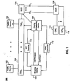
- FIG. 1 depicts a communications system according to embodiments of the present invention.
- FIG. 2 depicts a conventional transmit queue.
- FIG. 3 depicts transmit queues and a multiplexer according to embodiments of the present invention.
- FIG. 4 depicts a detailed view of a portion of the communications system of FIG. 1.
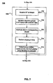
- FIG. 5 is a flowchart showing an overall method of operation of the communications system of FIG. 1 according to embodiments of the present invention.
- FIG. 6 is a flowchart showing an initialization portion of the method in FIG. 5.
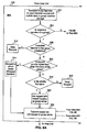
- FIG. 7 is a flowchart showing a cell request data shaping portion of the method in FIG. 5.
- FIGs. 8A and 8B is a flowchart showing a scheduling portion of the method in FIG. 5.
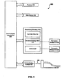
- FIG. 9 depicts a computer system according to embodiments of the present invention.
- a communications system and related method provide the capability to allow traffic source data from one or more transmit queues to be combined on a single VC and to allow the order of transmission from each group to be based on a QoS priority value that is assigned to each queue. It is to be understood that throughout the specification a "group" of transmit queues may include one or more transmit queues. This capability allows multiple service classes to share a VC without sacrificing the ability to prioritize one service class over another. For example, as shown in FIG.
- FIG. 1 illustrates a communications system 100, which may be part of an ATM network, according to embodiments of the present invention.
- the system 100 includes traffic sources 102 that send traffic source data (e.g., voice data, video data, Internet data, etc.) to a transmit queue 104.
- the transmit queue 104 sends cell request data (e.g., cell availability signals), which is based on the traffic source data, to a shaping device 106 and a priority scheduling device 108.
- the shaping device 106 shapes the cell request data and outputs a cell request to the priority scheduling device 108.
- the priority scheduling device 108 sends cell grant information to the shaping device 106 after a cell request has been granted.
- a shaping and cell transmission cycle is initiated by a shaper interval time (SIT) counter 110, which may be a programmable counter, that sends a SIT signal to the shaper 106 and priority scheduling device 108.
- a host controller 112 transmits initial parameters to the shaping device 106 and the priority scheduling device 108.
- CPE customer premise equipment
- FIG. 2 shows more detailed views of the transmit queues 104, shaping device 106, and priority scheduling device 108.
- the shaping device 106 includes traffic shapers 200 coupled to corresponding ones of the transmit data queues 104 and parameter storage devices 202 coupled to corresponding ones of the traffic shapers 200.
- Each of the traffic shapers 200 is coupled to a scheduler 204 in the priority scheduling device 108.
- the scheduler 204 is also coupled to a group identifier storage 206 and the multiplexer 114.
- the multiplexer 114 can include a plurality of multiplexers 208.
- the parameter storage devices 202 and the group identifier storage 206 are coupled to and initialized by the host controller 112.
- each operational VC is configured to have a group comprising either a single queue 104 (non-multi-priority mode) or to have multiple queues 104 (multi-priority mode).
- a VC is configured for multi-priority mode
- a multi-priority group is established for that VC by the host controller 112 in the group identifier storage 206.
- the group identifier storage 206 contains an enable bit and a unique identifier for each group.
- Each transmit queue 104 and associated traffic shaper 200 targeted for transmission on a particular multi-priority VC (group) becomes a member of that group.
- the host controller 112 initializes the traffic shaper 200 of each transmit queue 104 as a multi-priority VC member and identifies the member's group using the same unique identifier that was stored in the group identifier storage 206.
- the system 100 supports a configurable number of groups with any number of members in each group, for example from 1 to n.
- a transmit queue 104 can be a member of one member group (non_multi_priority mode) or one multi-priority VC group. If it is not a member of a multi-priority VC group, then the transmit queue 104 operates normally as one transmit queue per VC, which is known as per-VC queuing.
- transmit queues 104-0, 104-1, and 104-3 are all members of a first group (a multi-priority group) and are transmitted on VC-1 via multiplexer 208-1.
- transmit queue 104-2 is a member of a second group (a non-multi-priority group) and is transmitted on VC-2 via one multiplexer 208-2.
- transmit queues 208-(m-1) and 208-m are members of a third group and are transmitted on VC-m.
- the traffic shaping device 106 contains the individual traffic shapers 200, each of which is directly associated with a transmit queue 104.
- Each member of a particular multi-priority VC group has a shaper 200 that is configured by the host controller 112 with the same shaping parameters as all the other members according to the traffic shaping parameters of the VC.
- Each member of a particular group that has traffic source data available in its associated TX Queue 104 will generate a cell request according to the traffic shaping parameters of the VC at the same time as any other member that also has traffic source data available.
- the priority scheduling device 108 will compare the priority of cell requests for all members of a group and decide which member is to be granted the transmit request.
- the traffic shaper 200 for all members will update its shaping algorithm as if it received the cell grant, irregardless of whether a particular member received the cell grant or another member of the group received the cell grant. All members of a group must update the shaping algorithm so that the traffic shaping parameters of the VC are not exceeded.
- a method 500 according to embodiments of the present invention is shown in FIG. 5.
- the host controller 112 initializes the system 100 at step 502.
- the SIT counter 110 generates and transmits a pulse to the shaping device 106 and the priority scheduling device 108 at step 504.
- the shaping device 106 accesses and shapes cell request data from the transmit queues 104.
- the shaping device 106 shapes cell request data and outputs a cell request having a queue number, a queue priority, and a multi-priority group identifier value, if applicable, with each transmit request
- the priority scheduling device 108 receives cell requests from the shaping device 106 for each transmit queue 104 that has traffic source data available and has satisfied the requirements of the selected QoS parameters of the VC. As many as 'm' valid requests may be receive.
- the priority scheduling device 108 evaluates each request with respect to other requests to determine which request will be cell granted. In other words, the priority scheduler device schedules transmissions based on the cell request
- a method 600 that can be used to initialize the system 100 during step 502 is shown in FIG. 6.
- the queues 104 are configured to be either multi-priority (several queues within a group) or non-multi-priority (only one queue by itself in a group) at step 602.
- multi-priority groups are established in the group identifier storage 206 correlating to the configured groups from step 602.
- An enable bit and unique group identifier is stored for each group in the group identifier storage 206 at step 606.
- the same group identifier is stored in a corresponding parameter storage device 202 in step 608.
- a method 700 that can be used to access and shape cell request data from the queues 104 is shown in FIG. 7.
- a pulse from the SIT counter 110 is received at the shaping device 106 to start a shaping interval at step 702.
- Cell request data is received at the individual traffic shapers 200 from corresponding ones of the queues 104 at 706.
- the traffic shapers 200 based on the QoS parameters stored in the parameter storage devices 202 shape the cell request data.
- a cell request having a queue number, queue priority, and multiparty identifier, if applicable, is output from the traffic shapers 200 to the priority scheduling device 108 at step 710.
- FIGs. 8A-B depict a method 800 performed in the priority scheduling device 108 that prioritizes transmit cell requests from the shaping device 106.
- the priority scheduling device 108 will have 'n' stored group identifier values, each of which establishes a multi-priority group that consists of more than one member.
- the method 800 compares the group identifier of each cell request with the unique group identifiers stored in the group identifier storage 206 to determine if the request is a member of a particular multi-priority group at step 802. If the cell request is not a member of a multi-priority group, then the request is evaluated for priority against other non-multi-priority group requests and the established owner of other groups starting at step 806, as shown in FIG. 8B, which is described in detail below.
- the owner of a group is established according to the cell request priority of each member along with whether a member is currently transmitting a packet.
- the method 800 will first determine if the cell request or another member (cell request) of the group is already processing a cell request including a packet (that is included of one or more cells) on the VC at step 808. Any member in the process of transmitting a packet becomes the owner of the group by default. All other member requests are denied at step 810 until the current owner completes the processing of the packet. Whether the member's request priority is higher than that of other active member requests is determined at step 812. The cell request is granted to the member with the higher priority request at 814.
- FIG. 8B illustrates the operation of the priority scheduling device 108 when the member of the cell request is not a member of a group.
- a determination is made if another non-multi-priority group member request is already processing a cell request including a packet on a VC at step 806. Any non-multi-priority group member in the process of transmitting a packet becomes the owner of the non-multi-priority group by default. All other member requests are denied at step 824 until the current owner completes the processing of the packet. Whether the member's request priority is higher than that of other active member requests is determined at step 826. The cell request is granted to the member with the higher priority request at 828.
- the request priority of the group owner is then compared to the priority of all other group owner and non-multi-priority group requests.
- the priority scheduling device 108 completes the scheduling process by selecting the highest priority request from all groups and non-multi-priority groups.
- All members of a multi-priority VC group share a VC, therefore they are also sharing the QoS parameters of the VC in the traffic shaping device 106.
- a multi-priority VC is established to be a Constant Bit Rate (CBR) service with a Peak Cell Rate (PCR) of 'y', then a member will be transmitting at a rate of 'y' once it has attained cell grant status.
- CBR Constant Bit Rate
- PCR Peak Cell Rate
- the system 100 and method 500 provide for the combining of traffic source data from multiple sources on a single VC that allows a higher priority traffic source data packet to jump ahead of lower priority packets, which helps retain the QoS requirements of the higher priority services.
- the system 100 and method 500 accomplish the multi-priority VC scheduling without requiring a fixed configuration of the 'm' transmit queues 104 in regards to which group the queue 104 belongs. Also, simultaneous scheduling of many multi-priority and non-multi-priority VCs is allowed.
- the operation may be seen as being similar to that of a packet switch.
- packet switching when packets arriving on multiple input ports are all destined for the same output port, the switch must decide which packet will get sent to the output port first, second, etc.
- a packet switch will typically perform the packet scheduling in a round-robin or priority basis.
- the system 100 and method 500 according to embodiments of the present invention differs from this simple operation of a packet switch because the scheduling of packets from the multiple queues 104 must ensure that the total throughput from all transmit queues 104 does not exceed the QoS parameters of the VC.
- embodiments of the present invention perform cell-interleaving of packets from many sources onto a single output port, where the packet switch does not perform this operation. Further, a significant difference compared to the operation of a simple packet switch is in the present invention's ability to simultaneously schedule many multi-priority and non-multi-priority VCs, while retaining the QoS parameters of each.
- the system 100 and method 500 involve a communications system with a shaping device 106 and scheduling device 108, which may be integrated as part of an ATM Segmentation engine in an ATM network.
- the shaping device 106 and scheduling device 108 work together to schedule the higher priority traffic before lower priority traffic, while retaining the specified QoS constant bit rate (CBR) or variable bit rate (VBR) parameters of the multi-priority VC.
- CBR constant bit rate
- VBR variable bit rate
- the number of levels of priority and the number of supported multi-priority VCs can be modified to best fit the requirements of a specific implementation.
- There are no limitations in the number of transmit queues that can share a VC and there are no limitations in the number of multi-priority VCs that can be supported simultaneously.
- the system 100 can be implemented with logic devices to perform the functions and steps recited in FIGs. 5-8B.
- the functions and steps in FIGs. 5-8B can be implemented in a processor, such as a microprocessor, embedded processor, etc.
- the processor can execute computer program code to form the steps of the Figures.
- the computer program code can be stored on a computer useable medium such as memory, computer disk, or the like.
- FIG. 9 illustrates a computer system 900 having one or more processors, such as processor 904.
- Processor 904 can be a special purpose or a general purpose digital signal processor.
- the processor 904 is connected to a communications infrastructure 906 (for example, a bus or network).
- a communications infrastructure 906 for example, a bus or network.
- Computer system 900 also includes a main memory 908, preferably random access memory (RAM), and may also include a secondary memory 910.
- the secondary memory 910 may include, for example, a hard disk drive 912 and/or a removable storage drive 914, representing a floppy disk drive; a magnetic tape drive, an optical disk drive, etc.
- the removable storage drive 914 reads from and/or writes to a removable storage unit 918 in a well known manner.
- Removable storage unit 918 represents a floppy disk, magnetic tape, optical disk, etc, which is read by and written to by removable storage drive 914.
- the removable storage unit 918 includes a computer usable storage medium having stored therein computer software and/or data.
- secondary memory 910 may include other similar means for allowing computer programs or other instructions to be loaded into computer system 900.
- Such means may include, for example, a removable storage unit 922 and an interface 920.
- Examples of such means may include a program cartridge and cartridge interface (such as that found in video game devices), a removable memory chip (such as an EPROM, or PROM) and associated socket, and other removable storage units 922 and interfaces 920 which allow software and data to be transferred from the removable storage unit 922 to computer system 900.
- Computer system 900 may also include a communications interface 924.
- Communications interface 924 allows software and data to be transferred between computer system 900 and external devices. Examples of communications interface 924 may include a modem, a network interface (such as an Ethernet card), a communications port, a PCMCIA slot and card, etc.
- Software and data transferred via communications interface 924 are in the form of signals 928 which may be electronic, electromagnetic, optical or other signals capable of being received by communications interface 924. These signals 928 are provided to communications interface 924 via a communications path 926.
- Communications path 926 carries signals 928 and may be implemented using wire or cable, fiber optics, a phone line, a cellular phone link, an RF link and other communications channels.
- computer program medium and “computer usable medium” are used to generally refer to media such as removable storage drive 914, a hard disk installed in hard disk drive 912, and signals 928. These computer program products are means for providing software to computer system 900.
- Computer programs are stored in main memory 905 and/or secondary memory 910. Computer programs may also be received via communications interface 924. Such computer programs, when executed, enable the computer system 900 to implement the present invention as discussed herein. In particular, the computer programs, when executed, enable the processor 904 to implement the processes of the present invention, such as the method(s). Accordingly, such computer programs represent controllers of the computer system 900. Where the invention is implemented using software, the software may be stored in a computer program product and loaded into computer system 900 using removable storage drive 914, hard drive 912 or communications interface 924,
- Example embodiments of the present invention have been described herein. As noted elsewhere, these example embodiments have been described for illustrative purposes only, and are not limiting. Other embodiments are possible and are covered by the invention, Such embodiments will be apparent to persons skilled in the relevant art(s) based on the teachings contained herein. Thus, the breadth and scope of the present invention should not be limited by any of the above-described exemplary embodiments, but should be defined only in accordance with the following claims and their equivalence.
Landscapes
- Engineering & Computer Science (AREA)
- Computer Networks & Wireless Communication (AREA)
- Signal Processing (AREA)
- Data Exchanges In Wide-Area Networks (AREA)
Applications Claiming Priority (4)
| Application Number | Priority Date | Filing Date | Title |
|---|---|---|---|
| US35286202P | 2002-02-01 | 2002-02-01 | |
| US352862P | 2002-02-01 | ||
| US195529 | 2002-07-16 | ||
| US10/195,529 US20030147349A1 (en) | 2002-02-01 | 2002-07-16 | Communications systems and methods utilizing a device that performs per-service queuing |
Publications (3)
| Publication Number | Publication Date |
|---|---|
| EP1335540A2 true EP1335540A2 (de) | 2003-08-13 |
| EP1335540A3 EP1335540A3 (de) | 2003-08-27 |
| EP1335540B1 EP1335540B1 (de) | 2005-06-15 |
Family
ID=27616310
Family Applications (1)
| Application Number | Title | Priority Date | Filing Date |
|---|---|---|---|
| EP03001893A Expired - Lifetime EP1335540B1 (de) | 2002-02-01 | 2003-01-29 | Kommunikationssystem und Verfahren mit einer Vorrichtung zur Warteschlangenbildung pro Dienst |
Country Status (3)
| Country | Link |
|---|---|
| US (1) | US20030147349A1 (de) |
| EP (1) | EP1335540B1 (de) |
| DE (1) | DE60300827T2 (de) |
Families Citing this family (9)
| Publication number | Priority date | Publication date | Assignee | Title |
|---|---|---|---|---|
| ATE373911T1 (de) * | 2000-10-03 | 2007-10-15 | U4Ea Technologies Ltd | Datenflusssteuerung |
| DE60039725D1 (de) * | 2000-10-03 | 2008-09-11 | U4Ea Technologies Ltd | Datenüberwachung basierend auf einem daten-last-profil |
| WO2002030061A1 (en) * | 2000-10-03 | 2002-04-11 | U4Ea Technologies Limited | Filtering data flows |
| ES2491865T3 (es) * | 2000-10-03 | 2014-09-08 | Gos Holdings Limited | Control de flujo de información en una red de paquetes sobre la base de longitudes de paquetes conceptuales variables |
| US7339890B2 (en) * | 2002-02-01 | 2008-03-04 | Broadcom Corporation | Scalable, high-resolution asynchronous transfer mode traffic shaper and method |
| US20040225707A1 (en) * | 2003-05-09 | 2004-11-11 | Chong Huai-Ter Victor | Systems and methods for combining a slow data stream and a fast data stream into a single fast data stream |
| ES2229917B1 (es) * | 2003-07-15 | 2006-07-01 | Diseño De Sistemas En Silicio, S.A. | Procedimiento de gestion dinamica de recursos de sitemas de telecomunicaciones en funcion de la calidad de servicio y del tipo de servicio. |
| US8660137B2 (en) * | 2005-09-29 | 2014-02-25 | Broadcom Israel Research, Ltd. | Method and system for quality of service and congestion management for converged network interface devices |
| CA3034237C (en) | 2016-08-24 | 2023-06-13 | Viasat, Inc. | Device shaping in a communications network |
Family Cites Families (18)
| Publication number | Priority date | Publication date | Assignee | Title |
|---|---|---|---|---|
| US5793747A (en) * | 1996-03-14 | 1998-08-11 | Motorola, Inc. | Event-driven cell scheduler and method for supporting multiple service categories in a communication network |
| US6018527A (en) * | 1996-08-13 | 2000-01-25 | Nortel Networks Corporation | Queue service interval based cell scheduler with hierarchical queuing configurations |
| DE19634492B4 (de) * | 1996-08-26 | 2004-10-14 | Siemens Ag | Verfahren zum optimierten Übertragen von ATM-Zellen über Verbindungsabschnitte |
| US6408005B1 (en) * | 1997-09-05 | 2002-06-18 | Nec Usa, Inc. | Dynamic rate control scheduler for ATM networks |
| US6157614A (en) * | 1997-10-22 | 2000-12-05 | Netro Corporation | Wireless ATM network with high quality of service scheduling |
| US6570876B1 (en) * | 1998-04-01 | 2003-05-27 | Hitachi, Ltd. | Packet switch and switching method for switching variable length packets |
| US6198723B1 (en) * | 1998-04-14 | 2001-03-06 | Paxonet Communications, Inc. | Asynchronous transfer mode traffic shapers |
| US6532213B1 (en) * | 1998-05-15 | 2003-03-11 | Agere Systems Inc. | Guaranteeing data transfer delays in data packet networks using earliest deadline first packet schedulers |
| CA2245367A1 (en) * | 1998-08-19 | 2000-02-19 | Newbridge Networks Corporation | Two-component bandwidth scheduler having application in multi-class digital communication systems |
| JP3123537B2 (ja) * | 1999-02-24 | 2001-01-15 | 日本電気株式会社 | Atmバッファ制御方法ならびに装置及び同方法がプログラムされ記録された記録媒体 |
| US6876659B2 (en) * | 2000-01-06 | 2005-04-05 | International Business Machines Corporation | Enqueuing apparatus for asynchronous transfer mode (ATM) virtual circuit merging |
| US6757291B1 (en) * | 2000-02-10 | 2004-06-29 | Simpletech, Inc. | System for bypassing a server to achieve higher throughput between data network and data storage system |
| US7042883B2 (en) * | 2001-01-03 | 2006-05-09 | Juniper Networks, Inc. | Pipeline scheduler with fairness and minimum bandwidth guarantee |
| US7065569B2 (en) * | 2001-01-09 | 2006-06-20 | Turin Networks, Inc. | System and method for remote traffic management in a communication network |
| JP4605911B2 (ja) * | 2001-01-24 | 2011-01-05 | 富士通株式会社 | パケット送出装置 |
| US7230948B2 (en) * | 2001-06-01 | 2007-06-12 | Telefonaktiebolaget Lm Ericsson (Publ) | Bandwidth efficient Quality of Service separation of AAL2 traffic |
| US7099275B2 (en) * | 2001-09-21 | 2006-08-29 | Slt Logic Llc | Programmable multi-service queue scheduler |
| US6980513B2 (en) * | 2001-09-24 | 2005-12-27 | Transwitch Corporation | Methods and apparatus for the fair allocation of bandwidth among MCR and best effort service connections in an ATM switch |
-
2002
- 2002-07-16 US US10/195,529 patent/US20030147349A1/en not_active Abandoned
-
2003
- 2003-01-29 EP EP03001893A patent/EP1335540B1/de not_active Expired - Lifetime
- 2003-01-29 DE DE60300827T patent/DE60300827T2/de not_active Expired - Lifetime
Also Published As
| Publication number | Publication date |
|---|---|
| EP1335540B1 (de) | 2005-06-15 |
| US20030147349A1 (en) | 2003-08-07 |
| EP1335540A3 (de) | 2003-08-27 |
| DE60300827D1 (de) | 2005-07-21 |
| DE60300827T2 (de) | 2006-05-18 |
Similar Documents
| Publication | Publication Date | Title |
|---|---|---|
| EP0981878B1 (de) | Faire und effiziente ablaufsteuerung von paketen variabler längen in einer eingangsgepufferten mehrpunktvermittlung | |
| US6185221B1 (en) | Method and apparatus for fair and efficient scheduling of variable-size data packets in an input-buffered multipoint switch | |
| US6160812A (en) | Method and apparatus for supplying requests to a scheduler in an input buffered multiport switch | |
| US6839358B2 (en) | Relaying apparatus | |
| US20040165598A1 (en) | Switch fabric scheduling with fairness and priority consideration | |
| US20050094643A1 (en) | Method of and apparatus for variable length data packet transmission with configurable adaptive output scheduling enabling transmission on the same transmission link(s) of differentiated services for various traffic types | |
| EP1080560A1 (de) | Verfahren und vorrichtung zur weiterleitung von paketen von einer mehrzahl konkurrierder warteschlangen zu einem ausgang | |
| WO2004004190A2 (en) | Apparatus and method to switch packets using a switch fabric with memory | |
| JPH10190710A (ja) | アクセス調停方法 | |
| US20040083326A1 (en) | Switch scheduling algorithm | |
| WO2006036124A1 (en) | Improved handling of atm data | |
| JP2002217962A (ja) | 複数の入力ポートから出力ポートにデータパケットをスケジューリングする方法 | |
| EP1335540A2 (de) | Kommunikationssystem und Verfahren mit einer Vorrichtung zur Warteschlangenbildung pro Dienst | |
| WO2000065867A1 (en) | Scheduler implementing weighted fair queuing by a weight limited first in-first out methodology | |
| US7602797B2 (en) | Method and apparatus for request/grant priority scheduling | |
| US6212181B1 (en) | Method for using the departure queue memory bandwidth to support additional cell arrivals in an ATM switch | |
| JPH11510009A (ja) | 割付型並びに動的交換機フロー制御 | |
| JP2000101591A (ja) | セルスケジューラ | |
| James et al. | A 40 Gb/s packet switching architecture with fine-grained priorities | |
| JP2000501902A (ja) | 網交換機内のマルチポイントツーポイントアービトレーション | |
| JPH11510003A (ja) | ポイントツーマルチポイントアービトレーション |
Legal Events
| Date | Code | Title | Description |
|---|---|---|---|
| PUAI | Public reference made under article 153(3) epc to a published international application that has entered the european phase |
Free format text: ORIGINAL CODE: 0009012 |
|
| PUAL | Search report despatched |
Free format text: ORIGINAL CODE: 0009013 |
|
| AK | Designated contracting states |
Designated state(s): AT BE BG CH CY CZ DE DK EE ES FI FR GB GR HU IE IT LI LU MC NL PT SE SI SK TR |
|
| AX | Request for extension of the european patent |
Extension state: AL LT LV MK RO |
|
| AK | Designated contracting states |
Designated state(s): AT BE BG CH CY CZ DE DK EE ES FI FR GB GR HU IE IT LI LU MC NL PT SE SI SK TR |
|
| AX | Request for extension of the european patent |
Extension state: AL LT LV MK RO |
|
| 17P | Request for examination filed |
Effective date: 20040227 |
|
| 17Q | First examination report despatched |
Effective date: 20040326 |
|
| AKX | Designation fees paid |
Designated state(s): DE FR GB |
|
| GRAP | Despatch of communication of intention to grant a patent |
Free format text: ORIGINAL CODE: EPIDOSNIGR1 |
|
| GRAS | Grant fee paid |
Free format text: ORIGINAL CODE: EPIDOSNIGR3 |
|
| GRAA | (expected) grant |
Free format text: ORIGINAL CODE: 0009210 |
|
| AK | Designated contracting states |
Kind code of ref document: B1 Designated state(s): DE FR GB |
|
| REG | Reference to a national code |
Ref country code: GB Ref legal event code: FG4D |
|
| REF | Corresponds to: |
Ref document number: 60300827 Country of ref document: DE Date of ref document: 20050721 Kind code of ref document: P |
|
| ET | Fr: translation filed | ||
| PLBE | No opposition filed within time limit |
Free format text: ORIGINAL CODE: 0009261 |
|
| STAA | Information on the status of an ep patent application or granted ep patent |
Free format text: STATUS: NO OPPOSITION FILED WITHIN TIME LIMIT |
|
| 26N | No opposition filed |
Effective date: 20060316 |
|
| PGFP | Annual fee paid to national office [announced via postgrant information from national office to epo] |
Ref country code: FR Payment date: 20100209 Year of fee payment: 8 |
|
| PGFP | Annual fee paid to national office [announced via postgrant information from national office to epo] |
Ref country code: DE Payment date: 20100131 Year of fee payment: 8 Ref country code: GB Payment date: 20100121 Year of fee payment: 8 |
|
| GBPC | Gb: european patent ceased through non-payment of renewal fee |
Effective date: 20110129 |
|
| REG | Reference to a national code |
Ref country code: FR Ref legal event code: ST Effective date: 20110930 |
|
| PG25 | Lapsed in a contracting state [announced via postgrant information from national office to epo] |
Ref country code: FR Free format text: LAPSE BECAUSE OF NON-PAYMENT OF DUE FEES Effective date: 20110131 |
|
| PG25 | Lapsed in a contracting state [announced via postgrant information from national office to epo] |
Ref country code: GB Free format text: LAPSE BECAUSE OF NON-PAYMENT OF DUE FEES Effective date: 20110129 |
|
| REG | Reference to a national code |
Ref country code: DE Ref legal event code: R119 Ref document number: 60300827 Country of ref document: DE Effective date: 20110802 |
|
| PG25 | Lapsed in a contracting state [announced via postgrant information from national office to epo] |
Ref country code: DE Free format text: LAPSE BECAUSE OF NON-PAYMENT OF DUE FEES Effective date: 20110802 |