EP1335659B1 - Element gonflable destine a une gaine d'endoscope - Google Patents
Element gonflable destine a une gaine d'endoscope Download PDFInfo
- Publication number
- EP1335659B1 EP1335659B1 EP01270170A EP01270170A EP1335659B1 EP 1335659 B1 EP1335659 B1 EP 1335659B1 EP 01270170 A EP01270170 A EP 01270170A EP 01270170 A EP01270170 A EP 01270170A EP 1335659 B1 EP1335659 B1 EP 1335659B1
- Authority
- EP
- European Patent Office
- Prior art keywords
- flexible
- sheath
- endoscope assembly
- flexible sheath
- assembly according
- Prior art date
- Legal status (The legal status is an assumption and is not a legal conclusion. Google has not performed a legal analysis and makes no representation as to the accuracy of the status listed.)
- Expired - Lifetime
Links
- 239000000463 material Substances 0.000 claims abstract description 47
- 238000000034 method Methods 0.000 claims abstract description 11
- 239000012530 fluid Substances 0.000 claims description 33
- 238000003780 insertion Methods 0.000 claims description 25
- 230000037431 insertion Effects 0.000 claims description 25
- 239000000853 adhesive Substances 0.000 claims description 9
- 230000001070 adhesive effect Effects 0.000 claims description 9
- 238000004891 communication Methods 0.000 claims description 8
- 239000012858 resilient material Substances 0.000 claims description 5
- 229920000126 latex Polymers 0.000 claims description 4
- 229920002635 polyurethane Polymers 0.000 claims description 3
- 239000004814 polyurethane Substances 0.000 claims description 3
- 229920001651 Cyanoacrylate Polymers 0.000 claims description 2
- MWCLLHOVUTZFKS-UHFFFAOYSA-N Methyl cyanoacrylate Chemical group COC(=O)C(=C)C#N MWCLLHOVUTZFKS-UHFFFAOYSA-N 0.000 claims description 2
- 229920000915 polyvinyl chloride Polymers 0.000 claims description 2
- 239000004800 polyvinyl chloride Substances 0.000 claims description 2
- 230000001815 facial effect Effects 0.000 claims 3
- 230000002093 peripheral effect Effects 0.000 claims 3
- 229920001971 elastomer Polymers 0.000 claims 1
- 239000000806 elastomer Substances 0.000 claims 1
- 230000004927 fusion Effects 0.000 claims 1
- 229920002379 silicone rubber Polymers 0.000 claims 1
- 239000004945 silicone rubber Substances 0.000 claims 1
- 230000009977 dual effect Effects 0.000 abstract description 6
- 238000001574 biopsy Methods 0.000 description 10
- 230000000717 retained effect Effects 0.000 description 7
- 239000000523 sample Substances 0.000 description 7
- 230000033001 locomotion Effects 0.000 description 6
- FAPWRFPIFSIZLT-UHFFFAOYSA-M Sodium chloride Chemical compound [Na+].[Cl-] FAPWRFPIFSIZLT-UHFFFAOYSA-M 0.000 description 5
- 230000001413 cellular effect Effects 0.000 description 5
- 210000001519 tissue Anatomy 0.000 description 5
- 239000004816 latex Substances 0.000 description 3
- 208000019693 Lung disease Diseases 0.000 description 2
- 210000000621 bronchi Anatomy 0.000 description 2
- 239000000356 contaminant Substances 0.000 description 2
- 238000005516 engineering process Methods 0.000 description 2
- 239000013305 flexible fiber Substances 0.000 description 2
- 239000011780 sodium chloride Substances 0.000 description 2
- 238000012546 transfer Methods 0.000 description 2
- 208000012661 Dyskinesia Diseases 0.000 description 1
- 208000000616 Hemoptysis Diseases 0.000 description 1
- 230000001580 bacterial effect Effects 0.000 description 1
- 230000015572 biosynthetic process Effects 0.000 description 1
- 230000008933 bodily movement Effects 0.000 description 1
- 230000001680 brushing effect Effects 0.000 description 1
- 239000003795 chemical substances by application Substances 0.000 description 1
- 238000004140 cleaning Methods 0.000 description 1
- 210000001072 colon Anatomy 0.000 description 1
- 230000002380 cytological effect Effects 0.000 description 1
- 230000001419 dependent effect Effects 0.000 description 1
- 238000011161 development Methods 0.000 description 1
- 238000003745 diagnosis Methods 0.000 description 1
- 238000002405 diagnostic procedure Methods 0.000 description 1
- 201000010099 disease Diseases 0.000 description 1
- 208000037265 diseases, disorders, signs and symptoms Diseases 0.000 description 1
- 210000001198 duodenum Anatomy 0.000 description 1
- 239000013536 elastomeric material Substances 0.000 description 1
- 238000001839 endoscopy Methods 0.000 description 1
- 210000003238 esophagus Anatomy 0.000 description 1
- 239000000835 fiber Substances 0.000 description 1
- 238000005286 illumination Methods 0.000 description 1
- 238000010348 incorporation Methods 0.000 description 1
- 208000015181 infectious disease Diseases 0.000 description 1
- 230000002458 infectious effect Effects 0.000 description 1
- 230000001788 irregular Effects 0.000 description 1
- 238000002955 isolation Methods 0.000 description 1
- 238000012986 modification Methods 0.000 description 1
- 230000004048 modification Effects 0.000 description 1
- 230000017311 musculoskeletal movement, spinal reflex action Effects 0.000 description 1
- 230000003287 optical effect Effects 0.000 description 1
- 210000003200 peritoneal cavity Anatomy 0.000 description 1
- 210000004224 pleura Anatomy 0.000 description 1
- 201000003144 pneumothorax Diseases 0.000 description 1
- 229920000642 polymer Polymers 0.000 description 1
- 230000004044 response Effects 0.000 description 1
- 238000005070 sampling Methods 0.000 description 1
- 238000012414 sterilization procedure Methods 0.000 description 1
- 210000002784 stomach Anatomy 0.000 description 1
- 230000001225 therapeutic effect Effects 0.000 description 1
- 230000002792 vascular Effects 0.000 description 1
- XLYOFNOQVPJJNP-UHFFFAOYSA-N water Substances O XLYOFNOQVPJJNP-UHFFFAOYSA-N 0.000 description 1
Images
Classifications
-
- A—HUMAN NECESSITIES
- A61—MEDICAL OR VETERINARY SCIENCE; HYGIENE
- A61B—DIAGNOSIS; SURGERY; IDENTIFICATION
- A61B1/00—Instruments for performing medical examinations of the interior of cavities or tubes of the body by visual or photographical inspection, e.g. endoscopes; Illuminating arrangements therefor
- A61B1/00064—Constructional details of the endoscope body
- A61B1/00071—Insertion part of the endoscope body
- A61B1/0008—Insertion part of the endoscope body characterised by distal tip features
- A61B1/00082—Balloons
-
- A—HUMAN NECESSITIES
- A61—MEDICAL OR VETERINARY SCIENCE; HYGIENE
- A61B—DIAGNOSIS; SURGERY; IDENTIFICATION
- A61B1/00—Instruments for performing medical examinations of the interior of cavities or tubes of the body by visual or photographical inspection, e.g. endoscopes; Illuminating arrangements therefor
- A61B1/00142—Instruments for performing medical examinations of the interior of cavities or tubes of the body by visual or photographical inspection, e.g. endoscopes; Illuminating arrangements therefor with means for preventing contamination, e.g. by using a sanitary sheath
-
- A—HUMAN NECESSITIES
- A61—MEDICAL OR VETERINARY SCIENCE; HYGIENE
- A61B—DIAGNOSIS; SURGERY; IDENTIFICATION
- A61B1/00—Instruments for performing medical examinations of the interior of cavities or tubes of the body by visual or photographical inspection, e.g. endoscopes; Illuminating arrangements therefor
- A61B1/012—Instruments for performing medical examinations of the interior of cavities or tubes of the body by visual or photographical inspection, e.g. endoscopes; Illuminating arrangements therefor characterised by internal passages or accessories therefor
-
- A—HUMAN NECESSITIES
- A61—MEDICAL OR VETERINARY SCIENCE; HYGIENE
- A61B—DIAGNOSIS; SURGERY; IDENTIFICATION
- A61B1/00—Instruments for performing medical examinations of the interior of cavities or tubes of the body by visual or photographical inspection, e.g. endoscopes; Illuminating arrangements therefor
- A61B1/267—Instruments for performing medical examinations of the interior of cavities or tubes of the body by visual or photographical inspection, e.g. endoscopes; Illuminating arrangements therefor for the respiratory tract, e.g. laryngoscopes, bronchoscopes
-
- A—HUMAN NECESSITIES
- A61—MEDICAL OR VETERINARY SCIENCE; HYGIENE
- A61B—DIAGNOSIS; SURGERY; IDENTIFICATION
- A61B1/00—Instruments for performing medical examinations of the interior of cavities or tubes of the body by visual or photographical inspection, e.g. endoscopes; Illuminating arrangements therefor
- A61B1/273—Instruments for performing medical examinations of the interior of cavities or tubes of the body by visual or photographical inspection, e.g. endoscopes; Illuminating arrangements therefor for the upper alimentary canal, e.g. oesophagoscopes, gastroscopes
-
- A—HUMAN NECESSITIES
- A61—MEDICAL OR VETERINARY SCIENCE; HYGIENE
- A61M—DEVICES FOR INTRODUCING MEDIA INTO, OR ONTO, THE BODY; DEVICES FOR TRANSDUCING BODY MEDIA OR FOR TAKING MEDIA FROM THE BODY; DEVICES FOR PRODUCING OR ENDING SLEEP OR STUPOR
- A61M25/00—Catheters; Hollow probes
- A61M25/10—Balloon catheters
- A61M25/1011—Multiple balloon catheters
Definitions
- This invention relates generally to endoscopy, and more particularly to inflatable members attached to an endoscopic instrument.
- endoscopes for diagnostic and therapeutic purposes are widespread. For example, there are upper endoscopes for examination of the esophagus, stomach and duodenum, colonoscopes for the examination of the colon, angioscopes for vascular examination, bronchoscopes for examining the bronchi, laparoscopes for examining the peritoneal cavity, and arthroscopes for the examination of joint spaces.
- endoscopes for diagnostic and therapeutic purposes are widespread.
- endoscopes for examination of the esophagus, stomach and duodenum
- colonoscopes for the examination of the colon
- angioscopes for vascular examination
- bronchoscopes for examining the bronchi
- laparoscopes for examining the peritoneal cavity
- arthroscopes for the examination of joint spaces.
- An endoscope for examining the bronchial tract and conducting transbronchial biopsies is a good example of the usefulness of endoscopic technology.
- These devices known as flexible fiber optic bronchoscopes, are widely used in diagnosing pulmonary diseases since they are capable of reaching the more distal bronchi in the bronchial tract.
- the bronchoscope is generally structured to contain a fiber optic bundle within the elongated probe section.
- flexible fiber optic bronchoscopes In addition to providing a direct viewing capability, flexible fiber optic bronchoscopes generally possess a means to remove tissue samples, or other material from the bronchial tract for biopsy or culture purposes.
- Tissue samples for biopsy purposes may be collected using a biopsy forceps extending from the distal end of the bronchoscope or by brushing the suspect area to capture cellular material for subsequent microscopic examination.
- Another commonly used technique to collect cellular material is to wash, or lavage the suspect area.
- a saline solution is injected into the bronchial passage and subsequently withdrawn by suction through the distal end of the broncoscope to capture cellular material.
- the cellular material may be subjected to a cytological examination or culture.
- One difficulty encountered in the use of endoscopes is continuously maintaining the endoscopic probe in a selected location within a body passage during the examination. Movement of the endoscopic probe while it is positioned within a body passage may occur for a number of reasons. For example, movement of the endoscope may occur due to an unintended bodily movement of the operator while the patient is undergoing the examination, or by an involuntary movement of the patient in response to the examination. Once the distal end of the endoscope has been dislodged from its intended location, it must be carefully repositioned before the examination may be resumed. Movement of the endoscope within a body passage is particularly pronounced during bronchoscopic examinations, since the patient must continue to breathe during the examination.
- involuntary bronchospasmodic events within the bronchial passages may occur during the examination that will disrupt the location of the distal end of the bronchoscope.
- a significant additional difficulty resulting from unintended patient movement may arise when a biopsy procedure is conducted. Since a biopsy forceps or brush is generally used, an uncontrolled or unintended cutting of tissue in the passage due to patient movement may lead to hemoptysis. Moreover, since the biopsy forceps, or brush may reach and perforate the pleura, pneumothorax may also occur.
- Still another difficulty encountered in the use of endoscopes for diagnostic purposes is the inability to sealably isolate the distal end of the endoscope from the remainder of the body passage during an endoscopic examination.
- the fluid occupying the cavity is generally removed by means of a suction channel in the endoscope, which may be followed by the introduction of a gas through an additional channel in the endoscope to distend the internal space.
- Other endoscopic applications may require that a fluid be retained within the portion of the body passage that has been sealably isolated.
- the bronchoscope is used to gently irrigate the air spaces in a distal air passage with a saline solution.
- Isolation of the saline to the region surrounding the distal end of the bronchoscope is required so that cellular samples removed during the lavage are sufficiently localized to be of diagnostic value.
- the sample when collecting samples by lavage for use in the diagnosis of infectious pulmonary diseases, the sample must not be contaminated by bacterial or other agents transported to the distal end of the probe by the unrestrained movement of saline through the passage.
- endoscopic devices are configured to accept an outer disposable sheath that is positioned over the insertion tube of the endoscope to avoid the communication of disease from one patient to another.
- the sheath is comprised of a flexible, thin, resilient elastomeric material, such as latex, that fits over and snugly surrounds the insertion tube of the endoscopic device so the insertion tube is completely isolated from contaminants.
- the sheath is generally further comprised of a viewing window at the distal end, and a plurality of internal channels, or lumens, through which biopsy samples or fluids may be either introduced or removed. Accordingly, an additional difficulty encountered in the use of endoscopes concerns the incorporation of positioning and passage-blocking means into the disposable outer sheath.
- US 4676228 A discloses an endoscope insertion tube having a sheath extending from its proximal end to partially encapsulate the insertion tube.
- the sheath includes a pair of inflatable members at its distal end.
- the sheath does not extend all of the way to the distal end of the endoscope insertion tube so that it is not provided to isolate the insertion tube from the external environment because. Instead, the sheath appears to be provided for the sole purpose of providing a means to place expandable members around the insertion tube.
- US 6086528 A discloses an endoscope insertion tube that can be fitted with a guide tube to provide a passage for surgical instruments.
- the guide tube does not extend all of the way to the distal end of the insertion tube to isolate the insertion tube from the external environment.
- US 5489256 A discloses a sheath which is heat-shrunk onto an endoscope insertion tube. The nature of the heat-shrunk material would normally preclude it from expanding.
- US 5353783 discloses a sheath for an endoscope which does not enclose the distal end of the endoscope.
- the sheath includes an annular inflation member which is located at the proximal end of the sheath.
- the inflation member is provided for the purpose of inflating the sheath to allow the distal end of the insertion tube to be inserted into the proximal end of the sheath.
- WO 97/36536 discloses a urethroscope partially covered by a sheath having a balloon at its distal end. However, the tip of the urethroscope projects through the end of the sheath so that the sheath does not isolate the urethroscope from the external environment.
- the apparatus must be able to sealably close the passage to either retain fluids within a closed space, or to prevent a fluid from reoccupying the space during an examination.
- the apparatus must be compatible with disposable sheaths currently used with endoscopic devices. Further, the apparatus must be able to completely isolate the insertion tube from contaminants.
- the invention provides apparatus and methods for attaching and forming enclosed inflatable members on an endoscope assembly with a disposable sheath, according claims 1 and claim 22, respectively.
- the dependent claims are directed to embodiments thereof.
- an apparatus in accordance with the invention includes a flexible and resilient cuff member that is positioned on the outer surface of the disposable sheath and sealably and fixedly bonded to the sheath cover material at the cuff edges to form an annular space capable of inflation.
- the inflatable member formed thereby is inflated through a lumen internal to the sheath that has an opening into the interior annular space.
- the annular space may be divided into separate inflatable lobes.
- the cuff member is a flexible and resilient enclosed member that is substantially toroidal in shape that is positioned on the outer surface of the sheath.
- the inflatable member is formed from an excess length of sheath cover material disposed on the disposable sheath.
- a single reentrant fold of sheath material is formed with, an edge that is sealably and fixedly bonded to the sheath cover material to form an annular space capable of inflation.
- the excess length of cover material may be used to form members with dual reentrant folds that comprise inflatable members with single and dual inflatable lobes.
- the present invention is generally directed to inflatable members attached to an endoscopic instrument. Many of the specific details of certain embodiments of the invention are set forth in the following description and in Figures 4 and 6 to provide a thorough understanding of such embodiments.
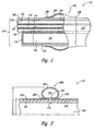
- FIG 1 is a partial cross sectional view of an endoscope assembly 10 with a circumferentially disposed inflatable cuff 100 which is not part of the invention.
- the endoscope assembly 10 includes an insertion tube 101 is positioned within a disposable endoscope sheath 103.
- the insertion tube 101 is generally semi-circular in cross section, and fabricated from a resilient material so that an insertion tube wall 102 may be flexed.
- the insertion tube 101 also has an internal space 104 that is structured to permit the illumination of tissue in internal passages, and to convey an image of the illuminated area from the distal end 110 of the endoscope to an external viewing device (not shown).
- the endoscope sheath 103 has a transparent viewing lens 118 located at the distal end 110 of the disposable sheath 103 to allow the image to be conveyed to the external viewing device.
- the sheath 103 also has a plurality of internal lumens to accomplish specific tasks.
- a lumen 124 may be provided to direct a flow of rinse water over the viewing lens 118 in order to rinse vision-impairing matter from the lens 118.
- a lumen 122 that is open at the distal end110 may be used to capture a biopsy sample taken from the surrounding tissue area by means of an elongated forceps, or brush (not shown).
- the lumen 122 may be used to transfer a saline solution into a body passage during a lavage procedure.
- the lumen 122 may also be used to transfer a compressed gas into a body passage in order to distend the passage for better optical viewing or biopsy sampling.
- An additional lumen 112 that is in fluid communication with a pressurized fluid source (not shown) is used to inflate an inflatable endoscope cuff 100, which will be described in greater detail below.
- the internal lumens 120,122 and 124 are comprised of a resilient material to maintain flexibility of the sheath 103.
- the sheath 103 is covered with a flexible, resilient cover material 130 such as latex, polyvinylchloride, or polyurethane.
- cover material 130 such as latex, polyvinylchloride, or polyurethane.
- other equally suitable materials for the cover material 130 are KRATONO, available from the GLS Corporation of McHenrylL, andC-FLEX@, available from Consolidated Polymer Technologies, Inc. of Largo, FL.
- an inflatable endoscope cuff 100 is comprised of a circular member with a fixed length and an internal diameter slightly smaller than the diameter of the sheath 103 to permit the cuff 100 to be snugly and circumferentially positioned on the outer surface of the sheath 103.
- the inflatable cuff 100 is preferably located near the distal end of the endoscope assembly 10, and forms a closed annular space 136 that is capable of inflation by a pressurized fluid.
- An opening 134 projects through the cover material 130 and through the wall of the lumen 120 to permit the pressurized fluid retained within the lumen 120 to enter the inflatable cuff 100.
- the cuff 100 is sealably fastened to the surface of the sheath 103 at the cuff edges138 with a suitable adhesive placed between the cuff edge 138 and the cover material 130.
- a suitable adhesive is cyanoacrylate, although other equivalent adhesives exist.
- the cuff edges 138 may be joined to the cover material 130 either by thermally fusing the cuff edges 138 to the cover material 130, or by wrapping lengths of surgical thread over the cuff edge 138 and securely tying the ends to sealably fasten the cuff edges138 to the cover material 130.
- the inflatable cuff 100 may be formed from latex, KRATONO, or C-FLEXO, although other suitable flexible and resilient materials may be used.
- soft polyurethane may also be used.
- the inflatable cuff 132 is formed from a flexible and resilient material with a thickness that ranges between 0.003 and 0.010 inches, with a durometer value of between approximately 30 and approximately 50.
- the inflatable endoscope cuff 200 is comprised of a resilient toroidally-shaped member 202 with an internal radius r and an external radius R.
- the internal radius r is selected to be slightly smaller than half the diameter of the sheath 103 when the member 202 is in a relaxed condition so that the member 202 may be snugly and circumferentially positioned on the outer surface of the sheath 103.
- An opening 134 projects through the cover material 130 and through the wall of the lumen 120 to permit a pressurized fluid retained within the lumen interior space 112 to enter the inflatable member 202 through an opening 210 in the interior diameter of the member 202.
- the toroidally-shaped member 202 is sealably fastened to the surface of the sheath 103 at a location that is closely proximate to the opening 134.
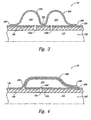
- FIG. 3 shows a partial cross sectional view of the endoscope assembly 10 with an embodiment of an inflatable endoscope cuff 300.
- the inflatable endoscope cuff 300 is comprised of a resilient circular member 302 with a fixed length and an internal diameter in a relaxed condition that is slightly smaller than the diameter of the sheath 103 that is snugly and circumferentially positioned on the outer surface of the sheath 103.
- the length of the endoscope cuff 300 is sufficient to allow the formation of a pair of inflatable annular lobes 310 and 320 by attaching the circular member 302 to the cover material 130 at an approximate midpoint location 350 of the cuff 300.
- the development of an inflatable endoscope member with dual lobes is regarded as particularly advantageous since the dual lobes are regarded as more effective in conforming to irregular internal surfaces in body passages.
- the cuff 300 may be retained at the midpoint location 350, and may be adhesively or thermally bonded to the cover material 30.
- the cuff may be attached to the cover material 130 at the mid point location 350 by a length of surgical thread wrapped around the cuff 300 that is securely knotted.
- cuff edges 340 are sealably joined to the cover material 130 using an adhesive or thermal bonding method as previously described. Openings 134a and 134b project through the cover material 130 and through the lumen wall 140 to permit the pressurized fluid retained in the lumen interior space 112 to enter the lobes310 and 320 during inflation.
- FIG. 4 a partial cross sectional view of the endoscope assembly 10 with yet another alternative embodiment of an inflatable endoscope member 400, which is not part of the invention, is shown.
- the endoscope assembly 10 advantageously allows an inflatable member to be formed on the disposable sheath 103 without placing a separate circumferential member on the disposable sheath 103.
- the inflatable member 400 is formed by providing an excess length of the cover material 130 on the sheath 103 that may be drawn along the surface of the sheath 103 by an edge fold 440 that extends circumferentially around the sheath 103 to form a reentrant fold 450 in the cover material 130 that also extends circumferentially around the disposable sheath 103.
- the edge fold 440 is subsequently sealably attached to the cover material 130 at a surface location 460 to form a closed annular space 410 that is capable of being inflated.
- the salable attachment between the edge fold 440 and the cover material 130 may be comprised of an adhesive or thermal bond.
- the attachment may be comprised of a length of surgical thread that is wrapped over the edge fold 440 and securely knotted.
- An opening 134 projects through the cover material 130 and through the wall of the lumen 120 to permit the pressurized fluid retained within the lumen interior space 112 to enter the inflatable annular member 400 during inflation.
- the member 400 may be sealably fastened to the surface of the sheath 103 at a location410 that is closely proximate to the opening 134 to ensure that the lumen opening 134 in the lumen wall 140 remains in substantial alignment with the opening 420 through the cover material 130.
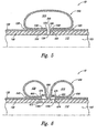
- FIG. 5 shows a partial cross sectional view of the endoscope assembly 10 with still another alternative embodiment of an inflatable endoscope member 500, which is not part of the invention.
- the inflatable endoscope member 500 is advantageously formed from an excess length of the cover material 130 that is disposed on the sheath 103.
- the excess length of the cover material 130 is drawn in a first direction along the surface of the sheath 103 to form a first reentrant fold 530 with a first edge fold 570.
- the first edge fold 570 is positioned approximately adjacent to the lumen opening 134.
- a second reentrant fold 540 is then formed in the cover material 130 by drawing the excess length in a second direction that is opposite to the first, to form a second edge fold 580 that is also positioned approximately adjacent to the lumen opening134.
- the first edge fold 570 and the second edge fold 580 form an opening 590 into the inflatable enclosed annular space 510.
- the first and second reentrant folds 530 and 540 are sealably attached to the lumen wall 140 at locations 550 and 560 to ensure that the lumen opening 134 remains in substantial alignment with the opening 590. Adhesive or thermal bonding may form the salable attachment at locations 550 and 560.
- surgical thread may be inserted into the first reentrant fold 530 through the opening 520 and also inserted into the second reentrant fold 540 through the opening 525, both lengths of surgical thread being wrapped around the circumference of the disposable sheath 103 and securely knotted to retain the inflatable member 500 in position on the sheath 103.
- FIG. 6 a partial cross sectional view of the endoscope assembly 10 with another alternative embodiment of an inflatable endoscope member 600 according to the invention is shown.
- the inflatable endoscope member 600 is similarly advantageously formed from an excess length of the cover material 130 that is disposed on the sheath 103. Drawing the excess length of cover material 130 along the surface of the sheath 103 in a first direction to form a first reentrant fold 660 with a first edge fold 670 forms the inflatable member 600. The first edge fold 670 is then positioned approximately adjacent to the opening 134a. Drawing the excess length in a second direction that is opposite to the first direction then forms a second reentrant fold 665 with a second edge fold 675.
- the second edge fold 675 is similarly positioned approximately adjacent to the opening 134b.
- the inflatable member 600 is divided into a pair of inflatable lobes 610 and 620 by attaching the cover material comprising the member 600 to the lumen wall 140 at an approximate midpoint location 680.
- the inflatable lobes 610 and 620 are inflated when pressurized fluid retained within the lumen interior space 112 enters the lobes through openings 134a and 134b.
- the first and second reentrant folds 660 and 665 are sealably attached to the lumen wall 140 at locations 672 and 674 to ensure that the lumen openings 134a and 134b remain in substantial alignment with the lobe entrances 661 and 662.
- adhesive or thermal bonding may be used to form the salable attachment at locations 672,674 and 680.
- surgical thread (not shown) may be used to retain the position of the inflatable member on the sheath 103.
Landscapes
- Health & Medical Sciences (AREA)
- Life Sciences & Earth Sciences (AREA)
- Surgery (AREA)
- Biomedical Technology (AREA)
- Medical Informatics (AREA)
- Optics & Photonics (AREA)
- Pathology (AREA)
- Radiology & Medical Imaging (AREA)
- Biophysics (AREA)
- Engineering & Computer Science (AREA)
- Physics & Mathematics (AREA)
- Heart & Thoracic Surgery (AREA)
- Nuclear Medicine, Radiotherapy & Molecular Imaging (AREA)
- Molecular Biology (AREA)
- Animal Behavior & Ethology (AREA)
- General Health & Medical Sciences (AREA)
- Public Health (AREA)
- Veterinary Medicine (AREA)
- Endoscopes (AREA)
- Instruments For Viewing The Inside Of Hollow Bodies (AREA)
- Materials For Medical Uses (AREA)
Claims (24)
- Assemblage d'endoscope destiné à venir s'insérer dans un passage interne dans un patient humain, comprenant :un tube d'insertion flexible allongé (101) ;un passage pour fluides (112, 134a, 134b) qui peut être activé pour se mettre en communication par fluide avec une source mise sous pression ;une gaine flexible imperméable aux fluides (103) possédant une extrémité distale et disposée par-dessus au moins une portion du tube d'insertion (101) et du passage pour fluides (112, 134a, 134b) ;caractérisé en ce quedes portions du passage pour fluides (112, 134a, 134b) s'étendent à travers la gaine flexible (103) pour définir plusieurs ouvertures (134a, 134b) dans la gaine flexible (103) ; etl'assemblage d'endoscope comprend en outre plusieurs membres flexibles circonférentiels (300 ; 600) aptes à s'élargir en direction radiale disposés sur l'extrémité distale de la gaine flexible (103) et fixés de manière étanche à la gaine flexible (103), chacun desdits plusieurs membres flexibles pouvant être activé pour former un espace annulaire gonflable renfermé en communication par fluide avec une ouverture respective parmi lesdites plusieurs ouvertures (134 ; 134a, 134b).
- Assemblage d'endoscope selon la revendication 1, dans lequel au moins un des membres flexibles (100, 200, 300, 400, 500, 600) comprend en outre une matière essentiellement résiliente.
- Assemblage d'endoscope selon la revendication 1, dans lequel le passage pour fluides (112, 134 ; 112, 134a, 134b) comprend en outre une lumière (112) s'étendant depuis les ouvertures (134 ; 134a, 134b) dans la gaine flexible (103) jusqu'à une source de fluide mis sous pression.
- Assemblage d'endoscope selon la revendication 1, comprenant en outre au moins une paire de lobes annulaires (310, 320) formés par le membre flexible circonférentiel (300) apte à s'élargir en direction radiale, dans lequel un endroit (350) situé approximativement à mi-distance du membre flexible circonférentiel (300) apte à s'élargir en direction radiale est fixé à la gaine flexible (103).
- Assemblage d'endoscope selon la revendication 1, dans lequel au moins un des membres flexibles (400) comprend en outre un pli rentrant (450) dans la gaine flexible (103) pour former une patte circonférentielle comprenant une base circonférentielle qui est contiguë au tube d'insertion flexible (101) et un bord circonférentiel (440) disposé à l'écart de la base, la patte s'étendant par-dessus l'ouverture (134) dans la gaine flexible (103) et le bord (440) étant fixé de manière étanche à la gaine flexible (103).
- Assemblage d'endoscope selon la revendication 1, dans lequel au moins un des membres flexibles (500) comprend en outre un premier pli rentrant (530 ; 665) dans la gaine flexible (103) pour former un premier bord circonférentiel (570 ; 670), et un deuxième pli rentrant (540 ; 660) dans la gaine flexible (103) pour former un deuxième bord circonférentiel (580 ; 665), les premier et deuxième bords venant essentiellement buter contre l'ouverture (134) et étant fixés de manière étanche à la gaine flexible (103) à proximité de l'ouverture (134) pour former un espace clos qui peut faire l'objet d'un gonflage.
- Assemblage d'endoscope selon la revendication 1, dans lequel au moins un des membres flexibles (600) comprend en outre un premier pli rentrant (660) dans la gaine flexible (103) pour former un premier bord circonférentiel (670), et un deuxième pli rentrant (665) dans la gaine flexible (103) pour former un deuxième bord circonférentiel (675), les premier et deuxième bords étant fixés de manière étanche à la gaine flexible (103) à proximité des ouvertures (134a, 134b), au moins un des membres flexibles (600) étant en outre fixé de manière étanche à la gaine flexible (103) à une position (680) intermédiaire entre les premier et deuxième bords circonférentiels (670, 675) pour former une paire d'espaces annulaires renfermés (610 ; 620), chaque espace étant mis en communication par fluide avec au moins une ouverture parmi lesdites plusieurs ouvertures (134a, 134b).
- Assemblage d'endoscope selon la revendication 1, dans lequel le membre flexible (100, 200, 300, 400, 500, 600) comprend en outre un anneau circulaire constitué d'une matière flexible présentant une face interne et une face externe, la face interne étant essentiellement mise en contact facial avec la gaine flexible (103) à l'état non gonflé, et la face externe étant disposée à l'écart de la gaine flexible (103) et possédant des premier et deuxième bords périphériques qui sont fixés de manière étanche à la gaine (103).
- Assemblage d'endoscope selon la revendication 1, dans lequel le membre flexible (200) comprend en outre un membre (202) de configuration toroïdale comprenant une circonférence interne et une circonférence externe, la circonférence interne étant mise en contact facial avec la gaine flexible (103) et la circonférence externe étant disposée à l'écart de la gaine (103), la circonférence interne possédant une ouverture (210) disposée par-dessus la première ouverture (134) dans la gaine flexible (103) et étant fixée de manière étanche à la gaine (103) à la circonférence interne.
- Assemblage d'endoscope selon la revendication 1, dans lequel au moins un des membres flexibles (300 ; 600) comprend en outre un anneau circulaire constitué d'une matière flexible présentant une face interne et une face externe, la face interne étant essentiellement mise en contact facial avec la gaine flexible (103) à l'état non gonflé, et la face externe étant disposée à l'écart de la gaine flexible (103) et possédant des premier et deuxième bords périphériques (340 ; 670, 675) qui sont fixés de manière étanche à la gaine (103), la face interne étant en outre fixée de manière étanche à la gaine flexible (103) à une position (350 ; 680) intermédiaire entre les premier et deuxième bords périphériques (340 ; 670, 675) pour former une paire d'espaces annulaires renfermés (310, 320 ; 610 ; 620), chaque espace (340 ; 670, 675) étant mis en communication par fluide avec au moins une ouverture parmi lesdites plusieurs ouvertures (134a, 134b).
- Assemblage d'endoscope selon la revendication 1, dans lequel au moins un des membres flexibles (100, 200, 300, 400, 500, 600) comprend en outre un caoutchouc de silicone.
- Assemblage d'endoscope selon la revendication 1, dans lequel au moins un des membres flexibles (100, 200, 300, 400, 500, 600) comprend en outre une matière de polyuréthane.
- Assemblage d'endoscope selon la revendication 1, dans lequel au moins un des membres flexibles (100, 200, 300, 400, 500, 600) comprend en outre un caoutchouc de latex.
- Assemblage d'endoscope selon la revendication 1, dans lequel au moins un des membres flexibles (100, 200, 300, 400, 500, 600) comprend en outre un élastomère possédant une valeur d'après duromètre entre approximativement 30 et 50.
- Assemblage d'endoscope selon la revendication 1, dans lequel au moins un des membres flexibles (100, 200, 300, 400, 500, 600) comprend du chlorure de polyvinyle.
- Assemblage d'endoscope selon la revendication 1, dans lequel au moins un des membres flexibles (300, 600) comprend une matière dont l'épaisseur s'élève d'approximativement environ 0,0762 mm (0,003 pouce) à approximativement environ 0,254 mm (0,010 pouce).
- Assemblage d'endoscope selon la revendication 1, dans lequel au moins un des membres flexibles (300, 600) est fixé de manière étanche à la gaine flexible (103) à l'aide d'un adhésif.
- Assemblage d'endoscope selon la revendication 17, dans lequel l'adhésif est du cyanoacrylate.
- Assemblage d'endoscope selon la revendication 1, dans lequel au moins un des membres flexibles (300, 600) est fixé de manière étanche à la gaine flexible (103) par fusion thermique.
- Assemblage d'endoscope selon la revendication 1, dans lequel au moins un des membres flexibles (300, 600) est fixé de manière étanche à la gaine flexible (103) à l'aide d'un fil chirurgical.
- Procédé de fabrication de plusieurs membres flexibles circonférentiels (300 ; 600) aptes à s'élargir en direction radiale sur un tube d'insertion (101) d'un assemblage d'endoscope, comprenant le fait de :tirer une gaine flexible imperméable aux fluides (103) par-dessus une portion d'une surface d'un tube d'insertion flexible allongé (101) ;former un passage pour fluides (112, 134 ; 112, 134a, 134b) qui s'étend à travers la gaine flexible (103) pour définir plusieurs ouvertures (134 ; 134a, 134b) dans la gaine (103) ; etformer plusieurs membres flexibles circonférentiels (300 ; 600) aptes à s'élargir en direction radiale, chacun desdits plusieurs membres flexibles étant mis en communication par fluide avec une ouverture respective parmi lesdites plusieurs ouvertures (134 ; 134a, 134b) dans la gaine flexible (103) pour définir un espace annulaire renfermé respectif (310, 320 ; 610, 620) qui est conçu pour être gonflé.
- Procédé selon la revendication 19, dans lequel l'étape de formation d'un passage pour fluides (112, 134 ; 112, 134a, 134b) comprend en outre la formation d'une lumière 112 s'étendant depuis les ouvertures (134 ; 134a, 134b) dans la gaine flexible (103) jusqu'à la source de fluide mis sous pression.
- Procédé selon la revendication 20, dans lequel l'étape de formation d'un membre flexible (400) comprend en outre le fait de former un pli rentrant (450) dans la gaine flexible (103) pour obtenir une patte circonférentielle comprenant un bord circonférentiel disposé à l'écart du tube d'insertion (101), le fait d'étendre la patte par-dessus au moins une des ouvertures (134) dans la gaine (103), et le fait de joindre de manière étanche le bord circonférentiel à la gaine flexible (103) pour former un espace annulaire renfermé mis en communication par fluide avec l'ouverture (134).
- Procédé selon la revendication 19, dans lequel l'étape de formation des membres flexibles (300 ; 600) comprend en outre un premier pli rentrant (530 ; 665) dans la gaine flexible (103) pour former un premier bord circonférentiel (570 ; 670), et un deuxième pli rentrant (540 ; 660) dans la gaine flexible (103) pour former un deuxième bord circonférentiel (580 ; 665), les premier et deuxième bords venant essentiellement buter contre l'ouverture (134 ; 134a, 134b) et étant fixés de manière étanche à la gaine flexible (103) à proximité de l'ouverture (134 ; 134a, 134b).
Applications Claiming Priority (3)
| Application Number | Priority Date | Filing Date | Title |
|---|---|---|---|
| US09/702,155 US6461294B1 (en) | 2000-10-30 | 2000-10-30 | Inflatable member for an endoscope sheath |
| US702155 | 2000-10-30 | ||
| PCT/US2001/051069 WO2002064028A1 (fr) | 2000-10-30 | 2001-10-26 | Element gonflable destine a une gaine d"endoscope |
Publications (3)
| Publication Number | Publication Date |
|---|---|
| EP1335659A1 EP1335659A1 (fr) | 2003-08-20 |
| EP1335659A4 EP1335659A4 (fr) | 2006-04-05 |
| EP1335659B1 true EP1335659B1 (fr) | 2011-04-20 |
Family
ID=24820072
Family Applications (1)
| Application Number | Title | Priority Date | Filing Date |
|---|---|---|---|
| EP01270170A Expired - Lifetime EP1335659B1 (fr) | 2000-10-30 | 2001-10-26 | Element gonflable destine a une gaine d'endoscope |
Country Status (6)
| Country | Link |
|---|---|
| US (1) | US6461294B1 (fr) |
| EP (1) | EP1335659B1 (fr) |
| AT (1) | ATE505999T1 (fr) |
| AU (1) | AU2002253843B2 (fr) |
| DE (1) | DE60144486D1 (fr) |
| WO (1) | WO2002064028A1 (fr) |
Cited By (4)
| Publication number | Priority date | Publication date | Assignee | Title |
|---|---|---|---|---|
| US10314471B2 (en) | 2013-05-21 | 2019-06-11 | Smart Medical Systems Ltd. | Endoscope reprocessing method |
| US10398295B2 (en) | 2014-12-22 | 2019-09-03 | Smart Medical Systems Ltd. | Balloon endoscope reprocessing system and method |
| US10456564B2 (en) | 2011-03-07 | 2019-10-29 | Smart Medical Systems Ltd. | Balloon-equipped endoscopic devices and methods thereof |
| US10835107B2 (en) | 2015-04-03 | 2020-11-17 | Smart Medical Systems Ltd. | Endoscope electro-pneumatic adaptor |
Families Citing this family (83)
| Publication number | Priority date | Publication date | Assignee | Title |
|---|---|---|---|---|
| US8888688B2 (en) | 2000-04-03 | 2014-11-18 | Intuitive Surgical Operations, Inc. | Connector device for a controllable instrument |
| US6610007B2 (en) | 2000-04-03 | 2003-08-26 | Neoguide Systems, Inc. | Steerable segmented endoscope and method of insertion |
| US6468203B2 (en) | 2000-04-03 | 2002-10-22 | Neoguide Systems, Inc. | Steerable endoscope and improved method of insertion |
| US8517923B2 (en) | 2000-04-03 | 2013-08-27 | Intuitive Surgical Operations, Inc. | Apparatus and methods for facilitating treatment of tissue via improved delivery of energy based and non-energy based modalities |
| US6984203B2 (en) | 2000-04-03 | 2006-01-10 | Neoguide Systems, Inc. | Endoscope with adjacently positioned guiding apparatus |
| US6974411B2 (en) | 2000-04-03 | 2005-12-13 | Neoguide Systems, Inc. | Endoscope with single step guiding apparatus |
| US6858005B2 (en) | 2000-04-03 | 2005-02-22 | Neo Guide Systems, Inc. | Tendon-driven endoscope and methods of insertion |
| US20020143237A1 (en) | 2000-10-30 | 2002-10-03 | Katsumi Oneda | Inflatable member for an endoscope sheath |
| US6793661B2 (en) * | 2000-10-30 | 2004-09-21 | Vision Sciences, Inc. | Endoscopic sheath assemblies having longitudinal expansion inhibiting mechanisms |
| AUPR785001A0 (en) * | 2001-09-21 | 2001-10-18 | Kleiner, Daniel E. | Tamponade apparatus and method of using same |
| CN1764416A (zh) | 2002-01-09 | 2006-04-26 | 新引导系统公司 | 用于内窥镜结肠切除术的设备和方法 |
| US6958035B2 (en) * | 2002-10-15 | 2005-10-25 | Dusa Pharmaceuticals, Inc | Medical device sheath apparatus and method of making and using same |
| US20040186349A1 (en) * | 2002-12-24 | 2004-09-23 | Usgi Medical Corp. | Apparatus and methods for achieving endoluminal access |
| WO2004067080A1 (fr) * | 2003-01-30 | 2004-08-12 | Sumitomo Bakelite Co., Ltd. | Ballonnet a perforer pourvu d'un endoscope |
| US8882657B2 (en) | 2003-03-07 | 2014-11-11 | Intuitive Surgical Operations, Inc. | Instrument having radio frequency identification systems and methods for use |
| US7736300B2 (en) * | 2003-04-14 | 2010-06-15 | Softscope Medical Technologies, Inc. | Self-propellable apparatus and method |
| US20070142709A1 (en) * | 2003-08-04 | 2007-06-21 | Vision-Sciences, Inc. | Sheath with channel for endoscope |
| US6939293B2 (en) | 2003-08-07 | 2005-09-06 | Chris N. Conteas | Gastrointestinal lavage system |
| US20050159645A1 (en) * | 2003-11-12 | 2005-07-21 | Bertolero Arthur A. | Balloon catheter sheath |
| EP1718193B1 (fr) * | 2004-02-09 | 2013-07-03 | Smart Medical Systems Ltd. | Ensemble endoscope |
| JP4652713B2 (ja) * | 2004-04-02 | 2011-03-16 | オリンパス株式会社 | 内視鏡治療装置 |
| US20050251091A1 (en) * | 2004-05-10 | 2005-11-10 | Usgi Medical Inc. | Apparatus and methods for transgastric tissue manipulation |
| DE102004052036A1 (de) * | 2004-10-26 | 2006-04-27 | Stm Medizintechnik Starnberg Gmbh | Endoskop mit alternierendem Vortrieb |
| WO2006063491A1 (fr) * | 2004-12-14 | 2006-06-22 | Kerang Jiang | Systeme d’endoscopie avec etui jetable et mode d’emploi |
| CN100339043C (zh) * | 2004-12-14 | 2007-09-26 | 姜克让 | 带有一次性鞘套的内窥镜系统及其使用方法 |
| US20060149127A1 (en) * | 2004-12-30 | 2006-07-06 | Seddiqui Fred R | Disposable multi-lumen catheter with reusable stylet |
| US8182422B2 (en) | 2005-12-13 | 2012-05-22 | Avantis Medical Systems, Inc. | Endoscope having detachable imaging device and method of using |
| US8797392B2 (en) | 2005-01-05 | 2014-08-05 | Avantis Medical Sytems, Inc. | Endoscope assembly with a polarizing filter |
| US8872906B2 (en) | 2005-01-05 | 2014-10-28 | Avantis Medical Systems, Inc. | Endoscope assembly with a polarizing filter |
| US8289381B2 (en) | 2005-01-05 | 2012-10-16 | Avantis Medical Systems, Inc. | Endoscope with an imaging catheter assembly and method of configuring an endoscope |
| US20080091063A1 (en) * | 2005-02-07 | 2008-04-17 | Smart Medical Systems, Ltd. | Endoscope assembly |
| US20070015989A1 (en) * | 2005-07-01 | 2007-01-18 | Avantis Medical Systems, Inc. | Endoscope Image Recognition System and Method |
| WO2007017854A2 (fr) * | 2005-08-08 | 2007-02-15 | Smart Medical Systems Ltd. | Endoscope guidee par ballonnet |
| EP3788944B1 (fr) | 2005-11-22 | 2024-02-28 | Intuitive Surgical Operations, Inc. | Système de détermination de la forme d'un instrument pliable |
| WO2007062066A2 (fr) | 2005-11-23 | 2007-05-31 | Neoguide Systems, Inc. | Cable de commande multibrin, non metallique, pour instruments orientables |
| WO2007087421A2 (fr) | 2006-01-23 | 2007-08-02 | Avantis Medical Systems, Inc. | Endoscope |
| US20070185383A1 (en) * | 2006-02-08 | 2007-08-09 | Vision-Sciences, Inc. | Tapered endoscopic protective sheath |
| US8287446B2 (en) | 2006-04-18 | 2012-10-16 | Avantis Medical Systems, Inc. | Vibratory device, endoscope having such a device, method for configuring an endoscope, and method of reducing looping of an endoscope |
| CN104887171B (zh) * | 2006-05-18 | 2018-03-20 | 智能医疗系统有限公司 | 柔性内窥系统及其功能 |
| WO2007137208A2 (fr) | 2006-05-19 | 2007-11-29 | Neoguide Systems, Inc. | Procédés et appareil pour afficher l'orientation tridimensionnelle d'une extrémité distale orientable d'un endoscope |
| US20070270646A1 (en) * | 2006-05-19 | 2007-11-22 | Perry Weiner | Cystoscope and disposable sheath system |
| JP2009537283A (ja) | 2006-05-19 | 2009-10-29 | アヴァンティス メディカル システムズ インコーポレイテッド | ビデオアーチファクトの影響を低減するための装置および方法 |
| US8529440B2 (en) | 2006-07-06 | 2013-09-10 | Smart Medical Systems Ltd. | Endoscopy systems |
| US7927272B2 (en) | 2006-08-04 | 2011-04-19 | Avantis Medical Systems, Inc. | Surgical port with embedded imaging device |
| US8307830B2 (en) * | 2006-09-29 | 2012-11-13 | Nellcor Puritan Bennett Llc | Endotracheal cuff and technique for using the same |
| US20080091073A1 (en) * | 2006-10-16 | 2008-04-17 | Chul Hi Park | Inflatable actuation device |
| US20080249358A1 (en) * | 2007-04-04 | 2008-10-09 | Olympus Medical Systems Corporation | Therapeutic method and therapeutic system that use overtube with balloons |
| US8064666B2 (en) | 2007-04-10 | 2011-11-22 | Avantis Medical Systems, Inc. | Method and device for examining or imaging an interior surface of a cavity |
| US20080275299A1 (en) * | 2007-05-01 | 2008-11-06 | Chul Hi Park | Actuation device |
| US8109903B2 (en) | 2007-05-21 | 2012-02-07 | Smart Medical Systems Ltd. | Catheter including a bendable portion |
| US10244928B2 (en) | 2007-09-05 | 2019-04-02 | Cogentix Medical, Inc. | Compact endoscope tip and method for constructing same |
| US9220398B2 (en) | 2007-10-11 | 2015-12-29 | Intuitive Surgical Operations, Inc. | System for managing Bowden cables in articulating instruments |
| US20090131752A1 (en) * | 2007-11-19 | 2009-05-21 | Chul Hi Park | Inflatable artificial muscle for elongated instrument |
| KR101583246B1 (ko) | 2008-02-06 | 2016-01-12 | 인튜어티브 서지컬 오퍼레이션즈 인코포레이티드 | 제동 능력을 가지고 있는 체절식 기구 |
| US8182418B2 (en) | 2008-02-25 | 2012-05-22 | Intuitive Surgical Operations, Inc. | Systems and methods for articulating an elongate body |
| CN102046064B (zh) * | 2008-03-31 | 2014-05-28 | 智能医疗系统有限公司 | 与内窥镜一起使用的组件 |
| US20090287045A1 (en) * | 2008-05-15 | 2009-11-19 | Vladimir Mitelberg | Access Systems and Methods of Intra-Abdominal Surgery |
| US9820719B2 (en) | 2008-06-19 | 2017-11-21 | Cogentix Medical, Inc. | Method and system for intrabody imaging |
| US8109985B2 (en) | 2008-07-23 | 2012-02-07 | Boston Scientific Scimed, Inc. | Occlusion crossing device and method |
| CN102256534B (zh) | 2008-10-20 | 2016-03-30 | 智能医疗系统有限公司 | 在内窥镜中使用的组件及其应用 |
| US9480390B2 (en) * | 2008-11-07 | 2016-11-01 | Ashkan Farhadi | Endoscope accessory |
| US9521945B2 (en) * | 2008-11-07 | 2016-12-20 | Ashkan Farhadi | Endoscope accessory |
| US8468637B2 (en) * | 2009-02-06 | 2013-06-25 | Endoclear Llc | Mechanically-actuated endotracheal tube cleaning device |
| DK2393538T3 (da) | 2009-02-06 | 2017-11-27 | Endoclear Llc | Anordninger til rengøring af endotrachealrør |
| EP3510913A1 (fr) | 2009-05-29 | 2019-07-17 | Smart Medical Systems Ltd. | Ensembles d'ancrage pour endoscopes |
| JP2013505058A (ja) * | 2009-09-17 | 2013-02-14 | 富士フイルム株式会社 | 能動的にサイズを変える機能を備える推進装置 |
| CN105147226A (zh) | 2010-03-09 | 2015-12-16 | 智能医疗系统有限公司 | 球囊内窥镜及其制造和使用方法 |
| EP2902066B1 (fr) | 2010-03-29 | 2021-03-10 | Endoclear LLC | Visualisation et nettoyage de voies aériennes |
| US9445714B2 (en) | 2010-03-29 | 2016-09-20 | Endoclear Llc | Endotracheal tube coupling adapters |
| WO2014089028A1 (fr) | 2012-12-04 | 2014-06-12 | Endoclear Llc | Dispositifs, systèmes et procédés de nettoyage par aspiration |
| WO2014093401A1 (fr) * | 2012-12-10 | 2014-06-19 | The Regents Of The University Of California | Système d'insertion de drain thoracique guidé par vidéo |
| EP2856926A1 (fr) | 2013-10-04 | 2015-04-08 | Tidi Products, LLC | Gaine pour un instrument médical ou dentaire |
| US9516995B2 (en) | 2013-12-17 | 2016-12-13 | Biovision Technologies, Llc | Surgical device for performing a sphenopalatine ganglion block procedure |
| US10016580B2 (en) | 2013-12-17 | 2018-07-10 | Biovision Technologies, Llc | Methods for treating sinus diseases |
| US9694163B2 (en) | 2013-12-17 | 2017-07-04 | Biovision Technologies, Llc | Surgical device for performing a sphenopalatine ganglion block procedure |
| US9510743B2 (en) | 2013-12-17 | 2016-12-06 | Biovision Technologies, Llc | Stabilized surgical device for performing a sphenopalatine ganglion block procedure |
| US9901246B2 (en) | 2014-02-05 | 2018-02-27 | Verathon Inc. | Cystoscopy system including a catheter endoscope and method of use |
| US20150216418A1 (en) | 2014-02-06 | 2015-08-06 | Dentsply International Inc. | Inspection of dental roots and the endodontic cavity space therein |
| USD731652S1 (en) | 2014-02-19 | 2015-06-09 | Tidi Products, Llc | Dental curing light sleeve |
| US10016575B2 (en) | 2014-06-03 | 2018-07-10 | Endoclear Llc | Cleaning devices, systems and methods |
| US10525240B1 (en) | 2018-06-28 | 2020-01-07 | Sandler Scientific LLC | Sino-nasal rinse delivery device with agitation, flow-control and integrated medication management system |
| US11219435B2 (en) | 2019-10-18 | 2022-01-11 | Bard Peripheral Vascular, Inc. | Method and system for use in a lung access procedure to aid in preventing pneumothorax |
| CN120267952B (zh) * | 2025-04-08 | 2025-12-02 | 昆明华圣科技有限公司 | 一种结肠ct造影检查充气装置 |
Family Cites Families (24)
| Publication number | Priority date | Publication date | Assignee | Title |
|---|---|---|---|---|
| JPS5431825Y2 (fr) | 1975-06-30 | 1979-10-04 | ||
| US4148307A (en) | 1975-12-26 | 1979-04-10 | Olympus Optical Company Limited | Tubular medical instrument having a flexible sheath driven by a plurality of cuffs |
| US4180076A (en) | 1977-05-06 | 1979-12-25 | Betancourt Victor M | Nasogastric catheters |
| US4176662A (en) | 1977-06-17 | 1979-12-04 | The United States Of America As Represented By The Administrator Of The National Aeronautics And Space Administration | Apparatus for endoscopic examination |
| US4224929A (en) | 1977-11-08 | 1980-09-30 | Olympus Optical Co., Ltd. | Endoscope with expansible cuff member and operation section |
| US4295464A (en) | 1980-03-21 | 1981-10-20 | Shihata Alfred A | Ureteric stone extractor with two ballooned catheters |
| US4404971A (en) | 1981-04-03 | 1983-09-20 | Leveen Harry H | Dual balloon catheter |
| EP0177124A3 (fr) * | 1984-07-18 | 1987-01-21 | Sumitomo Electric Industries Limited | Cathéter |
| US4676228A (en) * | 1985-10-25 | 1987-06-30 | Krasner Jerome L | Medical apparatus having inflatable cuffs and a middle expandable section |
| US5078681A (en) * | 1989-10-23 | 1992-01-07 | Olympus Optical Co., Ltd. | Balloon catheter apparatus with releasable distal seal and method of operation |
| US5025778A (en) * | 1990-03-26 | 1991-06-25 | Opielab, Inc. | Endoscope with potential channels and method of using the same |
| US5217001A (en) * | 1991-12-09 | 1993-06-08 | Nakao Naomi L | Endoscope sheath and related method |
| US5331947A (en) * | 1992-05-01 | 1994-07-26 | Shturman Cardiology Systems, Inc. | Inflatable sheath for introduction of ultrasonic catheter through the lumen of a fiber optic endoscope |
| CA2143639C (fr) * | 1992-09-01 | 2004-07-20 | Edwin L. Adair | Endoscope sterilisable dote de tubes jetables et separables |
| US5569161A (en) * | 1992-10-08 | 1996-10-29 | Wendell V. Ebling | Endoscope with sterile sleeve |
| US5855549A (en) * | 1993-08-18 | 1999-01-05 | Vista Medical Technologies, Inc. | Method of using an optical female urethroscope |
| US5857998A (en) * | 1994-06-30 | 1999-01-12 | Boston Scientific Corporation | Stent and therapeutic delivery system |
| US5980549A (en) * | 1995-07-13 | 1999-11-09 | Origin Medsystems, Inc. | Tissue separation cannula with dissection probe and method |
| US5925054A (en) * | 1996-02-20 | 1999-07-20 | Cardiothoracic Systems, Inc. | Perfusion device for maintaining blood flow in a vessel while isolating an anastomosis |
| US5685822A (en) * | 1996-08-08 | 1997-11-11 | Vision-Sciences, Inc. | Endoscope with sheath retaining device |
| US5810790A (en) * | 1996-11-19 | 1998-09-22 | Ebling; Wendell V. | Catheter with viewing system and port connector |
| US6007482A (en) | 1996-12-20 | 1999-12-28 | Madni; Asad M. | Endoscope with stretchable flexible sheath covering |
| US6086528A (en) * | 1997-09-11 | 2000-07-11 | Adair; Edwin L. | Surgical devices with removable imaging capability and methods of employing same |
| US6234958B1 (en) * | 1998-11-30 | 2001-05-22 | Medical Access Systems, Llc | Medical device introduction system including medical introducer having a plurality of access ports and methods of performing medical procedures with same |
-
2000
- 2000-10-30 US US09/702,155 patent/US6461294B1/en not_active Expired - Lifetime
-
2001
- 2001-10-26 AU AU2002253843A patent/AU2002253843B2/en not_active Ceased
- 2001-10-26 EP EP01270170A patent/EP1335659B1/fr not_active Expired - Lifetime
- 2001-10-26 AT AT01270170T patent/ATE505999T1/de not_active IP Right Cessation
- 2001-10-26 WO PCT/US2001/051069 patent/WO2002064028A1/fr not_active Ceased
- 2001-10-26 DE DE60144486T patent/DE60144486D1/de not_active Expired - Lifetime
Cited By (4)
| Publication number | Priority date | Publication date | Assignee | Title |
|---|---|---|---|---|
| US10456564B2 (en) | 2011-03-07 | 2019-10-29 | Smart Medical Systems Ltd. | Balloon-equipped endoscopic devices and methods thereof |
| US10314471B2 (en) | 2013-05-21 | 2019-06-11 | Smart Medical Systems Ltd. | Endoscope reprocessing method |
| US10398295B2 (en) | 2014-12-22 | 2019-09-03 | Smart Medical Systems Ltd. | Balloon endoscope reprocessing system and method |
| US10835107B2 (en) | 2015-04-03 | 2020-11-17 | Smart Medical Systems Ltd. | Endoscope electro-pneumatic adaptor |
Also Published As
| Publication number | Publication date |
|---|---|
| EP1335659A1 (fr) | 2003-08-20 |
| EP1335659A4 (fr) | 2006-04-05 |
| DE60144486D1 (de) | 2011-06-01 |
| US6461294B1 (en) | 2002-10-08 |
| ATE505999T1 (de) | 2011-05-15 |
| WO2002064028A1 (fr) | 2002-08-22 |
| AU2002253843B2 (en) | 2005-10-06 |
Similar Documents
| Publication | Publication Date | Title |
|---|---|---|
| EP1335659B1 (fr) | Element gonflable destine a une gaine d'endoscope | |
| AU2002253843A1 (en) | Inflatable member for an endoscope sheath | |
| AU2003213781C1 (en) | Inflatable member for an endoscope sheath | |
| US6793661B2 (en) | Endoscopic sheath assemblies having longitudinal expansion inhibiting mechanisms | |
| CA1262246A (fr) | Gaine protectrice pour endoscope et methode d'installation | |
| US5050585A (en) | Sheathed endoscope | |
| JP4738593B2 (ja) | 内視鏡の固定及び位置決め装置 | |
| US5419310A (en) | Partially inflated protective endoscope sheath | |
| JP4541559B2 (ja) | 可撓性スリーブを使用する結腸内プローブの推進 | |
| CN103781394B (zh) | 用于内窥镜的气囊状进入设备 | |
| US7122003B2 (en) | Endoscopic retractor instrument and associated method | |
| US5503616A (en) | Collapsible access channel system | |
| USRE37772E1 (en) | Endoscope | |
| US5746694A (en) | Endoscope biopsy channel liner and associated method | |
| US5702348A (en) | Disposable endoscopic sheath support and positioning assembly | |
| US20150080764A1 (en) | Disposable instrument including working channels for endoscopy | |
| JP2007536980A (ja) | マルチルーメン型配管で使用するためのコネクター | |
| JP2019531864A (ja) | 使い捨てシースデバイス | |
| WO2001000080A2 (fr) | Manchons de securite pour endoscopes | |
| CN217547996U (zh) | 薄膜通道结构 | |
| JP7627305B2 (ja) | 細長い内視鏡カバー | |
| CN113069070A (zh) | 一种前端角度可调的分体组合式胃镜 | |
| JP2020121058A (ja) | ミラーカテーテル |
Legal Events
| Date | Code | Title | Description |
|---|---|---|---|
| PUAI | Public reference made under article 153(3) epc to a published international application that has entered the european phase |
Free format text: ORIGINAL CODE: 0009012 |
|
| 17P | Request for examination filed |
Effective date: 20030516 |
|
| AK | Designated contracting states |
Designated state(s): AT BE CH CY DE DK ES FI FR GB GR IE IT LI LU MC NL PT SE TR |
|
| AX | Request for extension of the european patent |
Extension state: AL LT LV MK RO SI |
|
| A4 | Supplementary search report drawn up and despatched |
Effective date: 20060222 |
|
| 17Q | First examination report despatched |
Effective date: 20060630 |
|
| GRAP | Despatch of communication of intention to grant a patent |
Free format text: ORIGINAL CODE: EPIDOSNIGR1 |
|
| GRAS | Grant fee paid |
Free format text: ORIGINAL CODE: EPIDOSNIGR3 |
|
| GRAA | (expected) grant |
Free format text: ORIGINAL CODE: 0009210 |
|
| AK | Designated contracting states |
Kind code of ref document: B1 Designated state(s): AT BE CH CY DE DK ES FI FR GB GR IE IT LI LU MC NL PT SE TR |
|
| REG | Reference to a national code |
Ref country code: GB Ref legal event code: FG4D |
|
| REG | Reference to a national code |
Ref country code: CH Ref legal event code: EP |
|
| REG | Reference to a national code |
Ref country code: IE Ref legal event code: FG4D |
|
| REF | Corresponds to: |
Ref document number: 60144486 Country of ref document: DE Date of ref document: 20110601 Kind code of ref document: P |
|
| REG | Reference to a national code |
Ref country code: DE Ref legal event code: R096 Ref document number: 60144486 Country of ref document: DE Effective date: 20110601 |
|
| REG | Reference to a national code |
Ref country code: NL Ref legal event code: VDEP Effective date: 20110420 |
|
| PG25 | Lapsed in a contracting state [announced via postgrant information from national office to epo] |
Ref country code: PT Free format text: LAPSE BECAUSE OF FAILURE TO SUBMIT A TRANSLATION OF THE DESCRIPTION OR TO PAY THE FEE WITHIN THE PRESCRIBED TIME-LIMIT Effective date: 20110822 Ref country code: SE Free format text: LAPSE BECAUSE OF FAILURE TO SUBMIT A TRANSLATION OF THE DESCRIPTION OR TO PAY THE FEE WITHIN THE PRESCRIBED TIME-LIMIT Effective date: 20110420 |
|
| PG25 | Lapsed in a contracting state [announced via postgrant information from national office to epo] |
Ref country code: BE Free format text: LAPSE BECAUSE OF FAILURE TO SUBMIT A TRANSLATION OF THE DESCRIPTION OR TO PAY THE FEE WITHIN THE PRESCRIBED TIME-LIMIT Effective date: 20110420 Ref country code: ES Free format text: LAPSE BECAUSE OF FAILURE TO SUBMIT A TRANSLATION OF THE DESCRIPTION OR TO PAY THE FEE WITHIN THE PRESCRIBED TIME-LIMIT Effective date: 20110731 Ref country code: AT Free format text: LAPSE BECAUSE OF FAILURE TO SUBMIT A TRANSLATION OF THE DESCRIPTION OR TO PAY THE FEE WITHIN THE PRESCRIBED TIME-LIMIT Effective date: 20110420 Ref country code: GR Free format text: LAPSE BECAUSE OF FAILURE TO SUBMIT A TRANSLATION OF THE DESCRIPTION OR TO PAY THE FEE WITHIN THE PRESCRIBED TIME-LIMIT Effective date: 20110721 Ref country code: CY Free format text: LAPSE BECAUSE OF FAILURE TO SUBMIT A TRANSLATION OF THE DESCRIPTION OR TO PAY THE FEE WITHIN THE PRESCRIBED TIME-LIMIT Effective date: 20110420 Ref country code: FI Free format text: LAPSE BECAUSE OF FAILURE TO SUBMIT A TRANSLATION OF THE DESCRIPTION OR TO PAY THE FEE WITHIN THE PRESCRIBED TIME-LIMIT Effective date: 20110420 |
|
| PG25 | Lapsed in a contracting state [announced via postgrant information from national office to epo] |
Ref country code: NL Free format text: LAPSE BECAUSE OF FAILURE TO SUBMIT A TRANSLATION OF THE DESCRIPTION OR TO PAY THE FEE WITHIN THE PRESCRIBED TIME-LIMIT Effective date: 20110420 |
|
| PLBE | No opposition filed within time limit |
Free format text: ORIGINAL CODE: 0009261 |
|
| STAA | Information on the status of an ep patent application or granted ep patent |
Free format text: STATUS: NO OPPOSITION FILED WITHIN TIME LIMIT |
|
| PG25 | Lapsed in a contracting state [announced via postgrant information from national office to epo] |
Ref country code: DK Free format text: LAPSE BECAUSE OF FAILURE TO SUBMIT A TRANSLATION OF THE DESCRIPTION OR TO PAY THE FEE WITHIN THE PRESCRIBED TIME-LIMIT Effective date: 20110420 |
|
| 26N | No opposition filed |
Effective date: 20120123 |
|
| REG | Reference to a national code |
Ref country code: DE Ref legal event code: R097 Ref document number: 60144486 Country of ref document: DE Effective date: 20120123 |
|
| PG25 | Lapsed in a contracting state [announced via postgrant information from national office to epo] |
Ref country code: MC Free format text: LAPSE BECAUSE OF NON-PAYMENT OF DUE FEES Effective date: 20111031 |
|
| REG | Reference to a national code |
Ref country code: CH Ref legal event code: PL |
|
| PG25 | Lapsed in a contracting state [announced via postgrant information from national office to epo] |
Ref country code: DE Free format text: LAPSE BECAUSE OF NON-PAYMENT OF DUE FEES Effective date: 20120501 Ref country code: LI Free format text: LAPSE BECAUSE OF NON-PAYMENT OF DUE FEES Effective date: 20111031 Ref country code: CH Free format text: LAPSE BECAUSE OF NON-PAYMENT OF DUE FEES Effective date: 20111031 |
|
| REG | Reference to a national code |
Ref country code: IE Ref legal event code: MM4A |
|
| REG | Reference to a national code |
Ref country code: DE Ref legal event code: R119 Ref document number: 60144486 Country of ref document: DE Effective date: 20120501 |
|
| PG25 | Lapsed in a contracting state [announced via postgrant information from national office to epo] |
Ref country code: IE Free format text: LAPSE BECAUSE OF NON-PAYMENT OF DUE FEES Effective date: 20111026 |
|
| PG25 | Lapsed in a contracting state [announced via postgrant information from national office to epo] |
Ref country code: LU Free format text: LAPSE BECAUSE OF NON-PAYMENT OF DUE FEES Effective date: 20111026 |
|
| PG25 | Lapsed in a contracting state [announced via postgrant information from national office to epo] |
Ref country code: TR Free format text: LAPSE BECAUSE OF FAILURE TO SUBMIT A TRANSLATION OF THE DESCRIPTION OR TO PAY THE FEE WITHIN THE PRESCRIBED TIME-LIMIT Effective date: 20110420 |
|
| REG | Reference to a national code |
Ref country code: FR Ref legal event code: PLFP Year of fee payment: 15 |
|
| REG | Reference to a national code |
Ref country code: FR Ref legal event code: PLFP Year of fee payment: 16 |
|
| REG | Reference to a national code |
Ref country code: FR Ref legal event code: PLFP Year of fee payment: 17 |
|
| REG | Reference to a national code |
Ref country code: FR Ref legal event code: PLFP Year of fee payment: 18 |
|
| PGFP | Annual fee paid to national office [announced via postgrant information from national office to epo] |
Ref country code: FR Payment date: 20200914 Year of fee payment: 20 |
|
| PGFP | Annual fee paid to national office [announced via postgrant information from national office to epo] |
Ref country code: GB Payment date: 20201014 Year of fee payment: 20 Ref country code: IT Payment date: 20200911 Year of fee payment: 20 |
|
| REG | Reference to a national code |
Ref country code: GB Ref legal event code: PE20 Expiry date: 20211025 |
|
| PG25 | Lapsed in a contracting state [announced via postgrant information from national office to epo] |
Ref country code: GB Free format text: LAPSE BECAUSE OF EXPIRATION OF PROTECTION Effective date: 20211025 |