EP1336228B1 - Mecanisme de commande pour appareillages electriques - Google Patents
Mecanisme de commande pour appareillages electriques Download PDFInfo
- Publication number
- EP1336228B1 EP1336228B1 EP01997866A EP01997866A EP1336228B1 EP 1336228 B1 EP1336228 B1 EP 1336228B1 EP 01997866 A EP01997866 A EP 01997866A EP 01997866 A EP01997866 A EP 01997866A EP 1336228 B1 EP1336228 B1 EP 1336228B1
- Authority
- EP
- European Patent Office
- Prior art keywords
- contact elements
- plug contact
- extensions
- base frame
- pin
- Prior art date
- Legal status (The legal status is an assumption and is not a legal conclusion. Google has not performed a legal analysis and makes no representation as to the accuracy of the status listed.)
- Expired - Lifetime
Links
Images

Classifications
-
- H—ELECTRICITY
- H01—ELECTRIC ELEMENTS
- H01R—ELECTRICALLY-CONDUCTIVE CONNECTIONS; STRUCTURAL ASSOCIATIONS OF A PLURALITY OF MUTUALLY-INSULATED ELECTRICAL CONNECTING ELEMENTS; COUPLING DEVICES; CURRENT COLLECTORS
- H01R13/00—Details of coupling devices of the kinds covered by groups H01R12/70 or H01R24/00 - H01R33/00
- H01R13/46—Bases; Cases
- H01R13/52—Dustproof, splashproof, drip-proof, waterproof, or flameproof cases
- H01R13/527—Flameproof cases
-
- H—ELECTRICITY
- H01—ELECTRIC ELEMENTS
- H01R—ELECTRICALLY-CONDUCTIVE CONNECTIONS; STRUCTURAL ASSOCIATIONS OF A PLURALITY OF MUTUALLY-INSULATED ELECTRICAL CONNECTING ELEMENTS; COUPLING DEVICES; CURRENT COLLECTORS
- H01R13/00—Details of coupling devices of the kinds covered by groups H01R12/70 or H01R24/00 - H01R33/00
- H01R13/46—Bases; Cases
- H01R13/533—Bases, cases made for use in extreme conditions, e.g. high temperature, radiation, vibration, corrosive environment, pressure
Definitions
- the invention relates to a device with an explosion-proof housing, wherein a pressure-tight partition wall is provided with sealed feedthroughs for electrical lines between a housing interior and an outer terminal space, which are in the outer terminal compartment electrical connections for leads, as terminal connections for from the outside supplied, anklemmbare leads are formed, wherein a support member is provided for the terminal connections, which are connected to pin-like extensions and thus pass through the partition and wherein in the interior mating plug contact elements are provided for contacting the pin-like extensions.
- Devices such as valve actuators are such devices that are manufactured among other things in explosion-proof design.
- the inside of the device must be sealed pressure-resistant accordingly.
- the supplied from the outside supply and control lines must therefore be guided through pressure-tight sealed feedthroughs into the interior.
- terminals are arranged, to which the supply lines supplied from the outside can be clamped and to which also inside the housing through the sealing plug leading supply and control lines are connected.
- Object of the present invention is to provide in an explosion-proof device of the type mentioned an electrical connection through which a simple installation with little effort is possible, even in case of service a simple disassembly and assembly is possible while wiring errors are practically excluded and also Under confined conditions and a large number of contacts the required clearances and creepage distances can be reached and the connection of supply lines are simplified.
- the device is a valve actuator, that the support member itself forms the partition and that connected to the support member terminal connections with the extensions and located thereon plug contact elements in mutually offset planes and in the interior of the mating plug contact elements in complementary thereto staggered levels are arranged.
- the clamping terminals located at the outer ends of the plug contact elements are arranged in different planes.
- clear cross-section of the support member thus an increase in the distance of adjacent contacts or connection points is achieved, so that, as is usually the case with valve actuators, even under cramped conditions and large numbers of contacts complied with the required clearances and creepage distances can be.
- inside plug contact elements are offset according to the terminal connections and to match the mating plug contact elements, which are mounted in a holder.
- the terminal connections may in particular be arranged in groups, for example in three groups in mutually offset planes, and the mating plug contact elements of the holder may be arranged in planes complementary thereto.
- the partition also forms the support member for the terminal connections, which are connected directly via the pin-like extensions with the internal plug contact elements.
- a holder is provided for the mating plug-in contact elements, which has mating with the plug contact elements of the support member arranged receptacles for the therein particular definable mating plug contact elements. Wiring errors during assembly and after replacement of a unit unit are thus practically excluded, so that such work can be made by less skilled workers.
- the support member is inserted into a tubular base frame part, which is used as a built-in part tightly between the housing and an outer, the terminal compartment bounding end cap.
- This basic frame part allows easy pre-assembly and connection with the support member tightly inserted therein.
- the carrier part consists of a plastic injection-molded part and is connected by injection molding with the base frame part and that the pin-like extensions which connect the terminal connections with the plug contact elements are embedded by injection molding tightly into the carrier part.
- the use of the tubular base frame part is advantageous because good accessibility and handling is available for the injection process.
- the terminal connections with pin-like extensions and plug contact elements having contacts in a Inserted injection mold and miteingegossen directly during the injection process, so that on one side of the partition, the terminal connections and on the other side, the plug contact elements are accessible.
- the basic frame part with cast-in carrier part and contacts embedded tightly therein forms an insoluble unit after the curing of the potting compound.
- the injection molding material used is in particular a thermosetting resin based on epoxy resin.
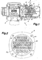
- a part of a valve actuator 1 is shown, of which in the longitudinal section, in particular of the electronics receiving housing part 2 and a housing portion 3 are shown with electrical connections 4.
- the housing part 2 is formed in explosion-proof design and sealed pressure-tight to the outside. Between the interior of this housing part and an outer connection space 5, a pressure-tight partition wall 6 is provided, at the same time forms a support member 7 for the electrical connections 4.
- the support member 7 is inserted into a tubular base frame part 8 which is a built-in part between the housing part 2 and an outer, the terminal compartment 5 bounding end cap 9 is located.
- Fig. 3 This basic frame part 8 is shown enlarged by dash-dotted lines end cover 9.
- the carrier part 7 from the outside with removed end cover 9 accessible terminal connections 10, which are connected to pin-like extensions 11 and thus pass through the partition 6 and the support member 7.
- plug contact elements 12 are provided, which are formed in the embodiment as sockets.
- the pin-like extensions 11 are solid in the course of their longitudinal extent and go at one end into the sockets and at the other end screw-in thread for the terminal connections 10 on. Overall, these contact parts are integrally formed.
- Counter plug contact elements 13 in the form of plugs are arranged in a holder 14 and held by this so that they are aligned with the plug contact elements 12.
- guides are provided for the correct position merging of these parts on the base frame part 8 and the holder 14.
- a groove 15 and the holder to a matching projection 16 are provided in the base frame part.
- the holder 14 receiving sleeves 25, in which the mating plug contact elements 13 are fixed after insertion In the in Fig. 1 and 3 shown mounting position, where the electrical connectors interlock, is the holder 14th set by an engaging in an annular groove 17 locking ring 18 in the axial direction.
- the formed as pins mating plug contact elements 13 are located within receiving cavities of the holder 14 and are axially fixed therein.
- electrical lines 19 are connected, which lead to assemblies within the housing part 2 ( Fig.1 ).
- the carrier part 7, which at the same time also forms the dividing wall 6, is connected in a pressure-tight manner to the tubular or tubular basic frame part 8.
- the material used is preferably a thermosetting resin based on epoxy resin.
- the injection process takes place at elevated temperature, for example, about 180 ° C.
- the contacts, so the terminal connections 10 with plug contact elements 12 and connecting them, pin-like extensions 11 are embedded in this injection process with the terminal connections 10 at the outside and the plug contact elements 12 at protrude the inside.
- the potting compound used is selected so that an adapted to the metallic base frame part 8 and the metallic, pin-like extensions 11 coefficient of thermal expansion is present.
- an elastic seal in the exemplary embodiment in the form of an O-ring 20, is used in the connection region between the base frame part 8 and the carrier part 7 ( Figure 3 ).
- form-fitting, interlocking, in particular circumferential profilings 21 in the form of annular grooves and projections are provided in this connection region.
- the support member 7 is additionally secured in the axial direction.
- the pin-like extensions 11 are, as in Fig. 3 shown, provided with annular grooves 22 or the like profiles, possibly also with knurls for increasing the surface area in order to achieve an improved seal.
- the terminal connections 10 are arranged in groups in mutually offset planes. In the embodiment, three mutually offset planes are provided. Also connected to the terminal connections 10, inside plug contact elements 12 are offset according to the terminal connections 10 and to match the mating plug contact elements 13 which are mounted in the holder 14.
- the staggering in several staircase-shaped levels allows for compact design compliance with the prescribed clearances and creepage distances even at radially comparatively small distances of the individual contacts.
- a relatively large number of electrical contacts can be arranged with clamping connections 10, wherein in the exemplary embodiment 42 such clamping connections 10 are provided (FIG. Fig. 2 ).
- the individual terminal connections 10 are shielded from each other by walls 26 bordering one another.
- the base frame part 8 made of metal, preferably made of die-cast aluminum. It has at its ends in each case connecting flanges 23, 24, via the connections on the one hand with the housing part 2 and on the other hand with the end cover 9 are possible. Also in the area of these compounds O-ring seals are provided.
Landscapes
- Connector Housings Or Holding Contact Members (AREA)
- Automobile Manufacture Line, Endless Track Vehicle, Trailer (AREA)
- Actuator (AREA)
- Vehicle Body Suspensions (AREA)
- Non-Portable Lighting Devices Or Systems Thereof (AREA)
- Fluid-Damping Devices (AREA)
- Motor Or Generator Frames (AREA)
- Fluid-Pressure Circuits (AREA)
- Magnetically Actuated Valves (AREA)
Claims (14)
- Mécanisme équipé d'un boîtier antidéflagration dans lequel une cloison séparatrice étanche à la pression, munie de traversées étanches destinées à des conducteurs électriques, est prévue entre un espace interne dudit boîtier et une chambre extérieure de raccordement (5), sachant que ladite chambre extérieure de raccordement (5) renferme des connexions électriques dédiées à des conducteurs d'arrivée et conçues comme des connexions par serrage (10) affectées à des conducteurs d'arrivée provenant de l'extérieur et pouvant être connectés par serrage, sachant qu'il est prévu une pièce (7) de support desdites connexions par serrage (10) reliées à des prolongements (11) du type chevilles, et traversant ainsi la cloison séparatrice (6), et sachant que des éléments complémentaires (13) de contact par enfichage sont prévus dans l'espace interne, afin d'établir un contact avec lesdits prolongements (11) du type chevilles, caractérisé par le fait que ledit mécanisme est un entraînement de réglage (1) pour robinetteries ; par le fait que la pièce de support (7) proprement dite matérialise la cloison séparatrice (6) ; et par le fait que les connexions par serrage (10), reliées à la pièce de support (7) et associées aux prolongements (11) et à des éléments enfichables de contact (12) qui s'y trouvent, sont disposées dans des plans mutuellement décalés, les éléments complémentaires (13) de contact par enfichage étant disposés, dans l'espace interne, dans des plans à décalage complémentaire.
- Mécanisme selon la revendication 1, caractérisé par le fait que la pièce de support (7) est logée dans une pièce tubulaire (8) d'encadrement de base interposée, en tant que pièce intégrée, entre le boîtier (2) et un couvercle obturateur extérieur (9) délimitant périphériquement la chambre de raccordement (5).
- Mécanisme selon la revendication 2, caractérisé par le fait que la pièce de support (7) est constituée d'une pièce venue de moulage par injection en matière plastique et reliée de manière étanche à la pièce (8) d'encadrement de base, par coulée par injection; et par le fait que les connexions par serrage (10) sont noyées de manière étanche dans ladite pièce de support (7) avec les éléments enfichables de contact (12), par coulée par injection, sur les prolongements (11) du type chevilles occupant des positions intercalaires.
- Mécanisme selon la revendication 2 ou 3, caractérisé par le fait que la pièce (8) d'encadrement de base consiste en un métal, de préférence en une pièce venue de coulée sous pression en aluminium comportant, à ses extrémités de raccordement, des brides de raccordement pourvues de logements récepteurs d'un moyen d'étanchement.
- Mécanisme selon l'une des revendications 1 à 4, caractérisé par la présence d'un support (14) dédié aux éléments complémentaires (13) de contact par enfichage et doté de logements (25) agencés de manière adaptée aux éléments enfichables de contact (12) de la pièce de support (7), lesdits logements étant destinés auxdits éléments complémentaires (13) de contact par enfichage pouvant, de préférence, y être consignés à demeure.
- Mécanisme selon la revendication 2 ou 5, caractérisé par le fait que la pièce (8) d'encadrement de base et le support (14) présentent des guides pour le guidage conjoint des pièces en position correcte ; et par le fait que, de préférence, au moins une rainure (15) est prévue dans ladite pièce (8) d'encadrement de base et une protubérance (16), complémentaire de ladite rainure, est prévue sur ledit support (14).
- Mécanisme selon la revendication 2 ou 5 ou 6, caractérisé par le fait qu'un élément d'arrêt, de préférence une bague d'arrêt (18) pénétrant dans une rainure annulaire (17) de la pièce (8) d'encadrement de base, est prévu dans la direction axiale d'emboîtement afin de bloquer la position du support (14) affecté aux éléments complémentaires (13) de contact par enfichage.
- Entraînement de réglage pour robinetteries, selon l'une des revendications 1 à 7, caractérisé par le fait que les éléments enfichables de contact (12) de la pièce de support (7) sont disposés, par groupes, dans des plans mutuellement décalés.
- Mécanisme selon l'une des revendications 5 à 8, caractérisé par le fait que les éléments enfichables de contact (12) de la pièce de support (7) sont des douilles, et les éléments complémentaires (13) de contact par enfichage du support (14) sont des fiches emboîtables dans lesdites douilles.
- Mécanisme selon l'une des revendications 5 à 9, caractérisé par le fait que la pièce de support (7) et le support (14) sont respectivement conçus pour recevoir une multiplicité d'éléments enfichables de contact (12) ou d'éléments complémentaires (13) de contact par enfichage, par exemple pour un nombre d'éléments respectifs de contact supérieur à 40.
- Mécanisme selon l'une des revendications 2 à 10, caractérisé par le fait que le matériau destiné à la pièce (8) d'encadrement de base, le matériau destiné à la pièce de support (7) intégrée par injection dans la pièce précitée, ainsi que le matériau constituant les prolongements (11) du type chevilles noyés dans ladite pièce de support, présentent des coefficients de dilatation thermique sensiblement identiques, adaptés les uns aux autres.
- Mécanisme selon l'une des revendications 2 à 11, caractérisé par le fait que des profilages (21) notamment périphériques, s'interpénétrant par concordance de formes et se présentant notamment comme des rainures et des protubérances annulaires, sont prévus dans la zone de liaison entre la pièce (8) d'encadrement de base et la pièce de support (7).
- Mécanisme selon l'une des revendications 2 à 12, caractérisé par le fait qu'une garniture élastique d'étanchement, de préférence au moins une bague torique (20), est utilisée pour assurer une étanchéité particulièrement résistante à la pression dans la zone de liaison entre la pièce (8) d'encadrement de base et la pièce de support (7).
- Mécanisme selon l'une des revendications 1 à 13, caractérisé par le fait que les prolongements (11) du type chevilles sont dotés de rainures annulaires (22) ou de profilages similaires comportant, le cas échéant, des moletages conçus pour agrandir la surface.
Applications Claiming Priority (3)
| Application Number | Priority Date | Filing Date | Title |
|---|---|---|---|
| DE10058107 | 2000-11-23 | ||
| DE10058107A DE10058107A1 (de) | 2000-11-23 | 2000-11-23 | Elektrogerät |
| PCT/EP2001/013293 WO2002043190A1 (fr) | 2000-11-23 | 2001-11-17 | Mecanisme de commande pour appareillages electriques |
Publications (2)
| Publication Number | Publication Date |
|---|---|
| EP1336228A1 EP1336228A1 (fr) | 2003-08-20 |
| EP1336228B1 true EP1336228B1 (fr) | 2008-06-25 |
Family
ID=7664347
Family Applications (1)
| Application Number | Title | Priority Date | Filing Date |
|---|---|---|---|
| EP01997866A Expired - Lifetime EP1336228B1 (fr) | 2000-11-23 | 2001-11-17 | Mecanisme de commande pour appareillages electriques |
Country Status (9)
| Country | Link |
|---|---|
| EP (1) | EP1336228B1 (fr) |
| AT (1) | ATE399377T1 (fr) |
| AU (1) | AU2002217041A1 (fr) |
| DE (2) | DE10058107A1 (fr) |
| DK (1) | DK1336228T3 (fr) |
| EA (1) | EA004839B1 (fr) |
| ES (1) | ES2306741T3 (fr) |
| WO (1) | WO2002043190A1 (fr) |
| ZA (1) | ZA200303395B (fr) |
Cited By (2)
| Publication number | Priority date | Publication date | Assignee | Title |
|---|---|---|---|---|
| DE202009004983U1 (de) * | 2009-07-03 | 2010-11-25 | Rema Lipprandt Gmbh & Co. Kg | Elektrischer Steckverbinder |
| DE102020125254A1 (de) | 2020-09-28 | 2022-03-31 | Krohne Messtechnik Gmbh | Gehäuse für ein elektronisches Feldgerät, Anschlussdurchführung und Verfahren |
Families Citing this family (3)
| Publication number | Priority date | Publication date | Assignee | Title |
|---|---|---|---|---|
| DE10317181C5 (de) * | 2003-04-15 | 2026-04-30 | Schischek GmbH | Antrieb, insbesondere Stell- und Regelantrieb, für Klappen und Armaturen |
| DE502006001382D1 (de) | 2006-01-11 | 2008-10-02 | Siemens Ag | Elektrische Einrichtung mit Ausschaltung des Laststromkreises in explosionsgefährdeter Umgebung |
| DE102021131953B3 (de) * | 2021-12-03 | 2023-05-17 | Auma Riester Gmbh & Co. Kg | Elektronisches Gerät und entsprechende Baureihe |
Citations (1)
| Publication number | Priority date | Publication date | Assignee | Title |
|---|---|---|---|---|
| DE9413463U1 (de) * | 1994-08-20 | 1994-11-03 | Gisma Steckverbinder GmbH, 24539 Neumünster | Vorrichtung zum Verbinden eines Kabels |
Family Cites Families (7)
| Publication number | Priority date | Publication date | Assignee | Title |
|---|---|---|---|---|
| FR2132532B1 (fr) * | 1971-04-07 | 1974-08-19 | Cables De Lyon Geoffroy Delore | |
| US3860315A (en) * | 1972-08-14 | 1975-01-14 | Anderson Power Products | Explosion proof connector |
| DE3507525C1 (de) * | 1985-03-04 | 1986-09-25 | Schulte-Elektrotechnik GmbH & Co KG, 5880 Lüdenscheid | Elektrischer Geraetestecker |
| DE3639485A1 (de) * | 1986-11-18 | 1988-05-26 | Karl Kapfer | Explosionsgeschuetztes elektrisches geraet |
| DE4002244C1 (fr) * | 1990-01-26 | 1991-05-08 | Abs Pumpen Ag, 5204 Lohmar, De | |
| US5147988A (en) * | 1990-05-22 | 1992-09-15 | Appleton Arthur I | Switching electrical receptacle |
| US6109979A (en) * | 1997-10-31 | 2000-08-29 | Micro Motion, Inc. | Explosion proof feedthrough connector |
-
2000
- 2000-11-23 DE DE10058107A patent/DE10058107A1/de not_active Withdrawn
-
2001
- 2001-11-17 AT AT01997866T patent/ATE399377T1/de active
- 2001-11-17 EP EP01997866A patent/EP1336228B1/fr not_active Expired - Lifetime
- 2001-11-17 DE DE50114055T patent/DE50114055D1/de not_active Expired - Lifetime
- 2001-11-17 WO PCT/EP2001/013293 patent/WO2002043190A1/fr not_active Ceased
- 2001-11-17 DK DK01997866T patent/DK1336228T3/da active
- 2001-11-17 EA EA200300598A patent/EA004839B1/ru not_active IP Right Cessation
- 2001-11-17 ES ES01997866T patent/ES2306741T3/es not_active Expired - Lifetime
- 2001-11-17 AU AU2002217041A patent/AU2002217041A1/en not_active Abandoned
-
2003
- 2003-05-02 ZA ZA200303395A patent/ZA200303395B/xx unknown
Patent Citations (1)
| Publication number | Priority date | Publication date | Assignee | Title |
|---|---|---|---|---|
| DE9413463U1 (de) * | 1994-08-20 | 1994-11-03 | Gisma Steckverbinder GmbH, 24539 Neumünster | Vorrichtung zum Verbinden eines Kabels |
Cited By (3)
| Publication number | Priority date | Publication date | Assignee | Title |
|---|---|---|---|---|
| DE202009004983U1 (de) * | 2009-07-03 | 2010-11-25 | Rema Lipprandt Gmbh & Co. Kg | Elektrischer Steckverbinder |
| DE102020125254A1 (de) | 2020-09-28 | 2022-03-31 | Krohne Messtechnik Gmbh | Gehäuse für ein elektronisches Feldgerät, Anschlussdurchführung und Verfahren |
| DE102020125254B4 (de) | 2020-09-28 | 2022-08-11 | Krohne Messtechnik Gmbh | Gehäuse für ein elektronisches Feldgerät und Anschlussdurchführung |
Also Published As
| Publication number | Publication date |
|---|---|
| ES2306741T3 (es) | 2008-11-16 |
| EA004839B1 (ru) | 2004-08-26 |
| ZA200303395B (en) | 2004-03-08 |
| EA200300598A1 (ru) | 2003-10-30 |
| EP1336228A1 (fr) | 2003-08-20 |
| AU2002217041A1 (en) | 2002-06-03 |
| DK1336228T3 (da) | 2008-10-27 |
| WO2002043190A1 (fr) | 2002-05-30 |
| DE50114055D1 (de) | 2008-08-07 |
| DE10058107A1 (de) | 2002-06-06 |
| ATE399377T1 (de) | 2008-07-15 |
Similar Documents
| Publication | Publication Date | Title |
|---|---|---|
| EP1947347B1 (fr) | Unité de pompage | |
| EP0586799B1 (fr) | Dispositif pour la fixation de câble pour pompe | |
| EP1947343B1 (fr) | Unité de pompage | |
| EP2517313B1 (fr) | Système de connexion par connecteur pour connexion électrique enfichable protégée contre l'humidité | |
| EP3069026B1 (fr) | Dispositif d'entraînement et de commande d'une pompe à vide, pompe à vide et procédé de fabrication d'une platine de commande destinée à une pompe à vide | |
| EP2095699A1 (fr) | Bloc de composants électriques et/ou électroniques | |
| DE10334655A1 (de) | Steckverbindervorrichtung für Kleinservomotoren | |
| DE3835755A1 (de) | Elektrohydraulische steuerungseinrichtung fuer hydraulische schreitausbau-einheiten | |
| DE102022212668A1 (de) | Elektrische Maschine mit Temperatursensor | |
| WO2002043190A1 (fr) | Mecanisme de commande pour appareillages electriques | |
| DE202015008215U1 (de) | Kontaktierungsvorrichtung, Anschlussgehäuse, Stellantrieb und Baureihe | |
| EP0124695B1 (fr) | Pince et manchon pour telle pince | |
| DE202017006808U1 (de) | Aggregatanschluss für ein Fahrzeug | |
| EP1950770B1 (fr) | Isolateur | |
| EP0073423B1 (fr) | Element de liaison d'un conducteur isolé par un corps solide | |
| DE10349706A1 (de) | Pneumatische Ventilanordnung mit einem Kanaltrennelement | |
| DE102022133217B3 (de) | Abgedichtete elektrische durchführung durch eine gehäusewand | |
| EP4231464B1 (fr) | Connecteur électrique, insert de contact et procédé de fabrication d'un connecteur électrique | |
| DE102022004518B3 (de) | Vorrichtung zum Herstellen einer elektrischen Verbindung zwischen einer Hochvolt-Leitung und einer Hochvolt-Komponente | |
| DE10313716A1 (de) | Elektrischer Steckverbinder und Verfahren zu seiner Herstellung | |
| EP4397528A1 (fr) | Boîte de charge pour un véhicule | |
| EP0690544A2 (fr) | Connexion de câble enfichable pour moteur électrique en capsule résistante à la pression d'une motopompe submersible | |
| EP3863158A1 (fr) | Module électrique d'essieu | |
| EP3391483B1 (fr) | Système d'entraînement pour former une section de séparation pour un dispositif de protection contre les surtensions | |
| EP4546575A1 (fr) | Boîtier de montage avec joint d'étanchéité |
Legal Events
| Date | Code | Title | Description |
|---|---|---|---|
| PUAI | Public reference made under article 153(3) epc to a published international application that has entered the european phase |
Free format text: ORIGINAL CODE: 0009012 |
|
| 17P | Request for examination filed |
Effective date: 20030509 |
|
| AK | Designated contracting states |
Designated state(s): AT BE CH CY DE DK ES FI FR GB GR IE IT LI LU MC NL PT SE TR |
|
| AX | Request for extension of the european patent |
Extension state: AL LT LV MK RO SI |
|
| GBC | Gb: translation of claims filed (gb section 78(7)/1977) | ||
| RAP1 | Party data changed (applicant data changed or rights of an application transferred) |
Owner name: AUMA RIESTER GMBH & CO. KG |
|
| 17Q | First examination report despatched |
Effective date: 20041020 |
|
| GRAP | Despatch of communication of intention to grant a patent |
Free format text: ORIGINAL CODE: EPIDOSNIGR1 |
|
| GRAS | Grant fee paid |
Free format text: ORIGINAL CODE: EPIDOSNIGR3 |
|
| GRAA | (expected) grant |
Free format text: ORIGINAL CODE: 0009210 |
|
| AK | Designated contracting states |
Kind code of ref document: B1 Designated state(s): AT BE CH CY DE DK ES FI FR GB GR IE IT LI LU MC NL PT SE TR |
|
| AX | Request for extension of the european patent |
Extension state: RO SI |
|
| REG | Reference to a national code |
Ref country code: GB Ref legal event code: FG4D Free format text: NOT ENGLISH |
|
| REG | Reference to a national code |
Ref country code: CH Ref legal event code: EP |
|
| REF | Corresponds to: |
Ref document number: 50114055 Country of ref document: DE Date of ref document: 20080807 Kind code of ref document: P |
|
| REG | Reference to a national code |
Ref country code: CH Ref legal event code: NV Representative=s name: HANS RUDOLF GACHNANG PATENTANWALT Ref country code: CH Ref legal event code: PCOW Free format text: AUMA RIESTER GMBH & CO. KG;AUMASTRASSE 1;79379 MUELLHEIM (DE) |
|
| REG | Reference to a national code |
Ref country code: IE Ref legal event code: FG4D Free format text: LANGUAGE OF EP DOCUMENT: GERMAN |
|
| REG | Reference to a national code |
Ref country code: SE Ref legal event code: TRGR |
|
| PG25 | Lapsed in a contracting state [announced via postgrant information from national office to epo] |
Ref country code: FI Free format text: LAPSE BECAUSE OF FAILURE TO SUBMIT A TRANSLATION OF THE DESCRIPTION OR TO PAY THE FEE WITHIN THE PRESCRIBED TIME-LIMIT Effective date: 20080625 |
|
| REG | Reference to a national code |
Ref country code: ES Ref legal event code: FG2A Ref document number: 2306741 Country of ref document: ES Kind code of ref document: T3 |
|
| PG25 | Lapsed in a contracting state [announced via postgrant information from national office to epo] |
Ref country code: PT Free format text: LAPSE BECAUSE OF FAILURE TO SUBMIT A TRANSLATION OF THE DESCRIPTION OR TO PAY THE FEE WITHIN THE PRESCRIBED TIME-LIMIT Effective date: 20081125 |
|
| REG | Reference to a national code |
Ref country code: IE Ref legal event code: FD4D |
|
| PG25 | Lapsed in a contracting state [announced via postgrant information from national office to epo] |
Ref country code: IE Free format text: LAPSE BECAUSE OF FAILURE TO SUBMIT A TRANSLATION OF THE DESCRIPTION OR TO PAY THE FEE WITHIN THE PRESCRIBED TIME-LIMIT Effective date: 20080625 |
|
| PLBE | No opposition filed within time limit |
Free format text: ORIGINAL CODE: 0009261 |
|
| STAA | Information on the status of an ep patent application or granted ep patent |
Free format text: STATUS: NO OPPOSITION FILED WITHIN TIME LIMIT |
|
| BERE | Be: lapsed |
Owner name: AUMA RIESTER G.M.B.H. & CO. KG Effective date: 20081130 |
|
| 26N | No opposition filed |
Effective date: 20090326 |
|
| PG25 | Lapsed in a contracting state [announced via postgrant information from national office to epo] |
Ref country code: MC Free format text: LAPSE BECAUSE OF NON-PAYMENT OF DUE FEES Effective date: 20081130 |
|
| PG25 | Lapsed in a contracting state [announced via postgrant information from national office to epo] |
Ref country code: BE Free format text: LAPSE BECAUSE OF NON-PAYMENT OF DUE FEES Effective date: 20081130 |
|
| PG25 | Lapsed in a contracting state [announced via postgrant information from national office to epo] |
Ref country code: CY Free format text: LAPSE BECAUSE OF FAILURE TO SUBMIT A TRANSLATION OF THE DESCRIPTION OR TO PAY THE FEE WITHIN THE PRESCRIBED TIME-LIMIT Effective date: 20080625 |
|
| PG25 | Lapsed in a contracting state [announced via postgrant information from national office to epo] |
Ref country code: TR Free format text: LAPSE BECAUSE OF FAILURE TO SUBMIT A TRANSLATION OF THE DESCRIPTION OR TO PAY THE FEE WITHIN THE PRESCRIBED TIME-LIMIT Effective date: 20080625 |
|
| PG25 | Lapsed in a contracting state [announced via postgrant information from national office to epo] |
Ref country code: GR Free format text: LAPSE BECAUSE OF FAILURE TO SUBMIT A TRANSLATION OF THE DESCRIPTION OR TO PAY THE FEE WITHIN THE PRESCRIBED TIME-LIMIT Effective date: 20080926 |
|
| REG | Reference to a national code |
Ref country code: CH Ref legal event code: NV Representative=s name: GACHNANG AG PATENTANWAELTE, CH |
|
| PGFP | Annual fee paid to national office [announced via postgrant information from national office to epo] |
Ref country code: LU Payment date: 20141023 Year of fee payment: 14 Ref country code: ES Payment date: 20140915 Year of fee payment: 14 |
|
| PGFP | Annual fee paid to national office [announced via postgrant information from national office to epo] |
Ref country code: DK Payment date: 20141124 Year of fee payment: 14 |
|
| PGFP | Annual fee paid to national office [announced via postgrant information from national office to epo] |
Ref country code: DE Payment date: 20141110 Year of fee payment: 14 Ref country code: FR Payment date: 20140922 Year of fee payment: 14 Ref country code: CH Payment date: 20141124 Year of fee payment: 14 Ref country code: SE Payment date: 20141124 Year of fee payment: 14 Ref country code: GB Payment date: 20141117 Year of fee payment: 14 |
|
| PGFP | Annual fee paid to national office [announced via postgrant information from national office to epo] |
Ref country code: AT Payment date: 20141126 Year of fee payment: 14 Ref country code: NL Payment date: 20141030 Year of fee payment: 14 |
|
| PGFP | Annual fee paid to national office [announced via postgrant information from national office to epo] |
Ref country code: IT Payment date: 20141126 Year of fee payment: 14 |
|
| REG | Reference to a national code |
Ref country code: DE Ref legal event code: R119 Ref document number: 50114055 Country of ref document: DE |
|
| REG | Reference to a national code |
Ref country code: DK Ref legal event code: EBP Effective date: 20151130 |
|
| PG25 | Lapsed in a contracting state [announced via postgrant information from national office to epo] |
Ref country code: LU Free format text: LAPSE BECAUSE OF NON-PAYMENT OF DUE FEES Effective date: 20151117 |
|
| REG | Reference to a national code |
Ref country code: CH Ref legal event code: PL |
|
| REG | Reference to a national code |
Ref country code: AT Ref legal event code: MM01 Ref document number: 399377 Country of ref document: AT Kind code of ref document: T Effective date: 20151117 |
|
| GBPC | Gb: european patent ceased through non-payment of renewal fee |
Effective date: 20151117 |
|
| PG25 | Lapsed in a contracting state [announced via postgrant information from national office to epo] |
Ref country code: IT Free format text: LAPSE BECAUSE OF NON-PAYMENT OF DUE FEES Effective date: 20151117 Ref country code: LI Free format text: LAPSE BECAUSE OF NON-PAYMENT OF DUE FEES Effective date: 20151130 Ref country code: CH Free format text: LAPSE BECAUSE OF NON-PAYMENT OF DUE FEES Effective date: 20151130 |
|
| REG | Reference to a national code |
Ref country code: NL Ref legal event code: MM Effective date: 20151201 |
|
| REG | Reference to a national code |
Ref country code: FR Ref legal event code: ST Effective date: 20160729 |
|
| PG25 | Lapsed in a contracting state [announced via postgrant information from national office to epo] |
Ref country code: SE Free format text: LAPSE BECAUSE OF NON-PAYMENT OF DUE FEES Effective date: 20151118 Ref country code: AT Free format text: LAPSE BECAUSE OF NON-PAYMENT OF DUE FEES Effective date: 20151117 |
|
| PG25 | Lapsed in a contracting state [announced via postgrant information from national office to epo] |
Ref country code: NL Free format text: LAPSE BECAUSE OF NON-PAYMENT OF DUE FEES Effective date: 20151201 |
|
| PG25 | Lapsed in a contracting state [announced via postgrant information from national office to epo] |
Ref country code: GB Free format text: LAPSE BECAUSE OF NON-PAYMENT OF DUE FEES Effective date: 20151117 Ref country code: DK Free format text: LAPSE BECAUSE OF NON-PAYMENT OF DUE FEES Effective date: 20151130 Ref country code: DE Free format text: LAPSE BECAUSE OF NON-PAYMENT OF DUE FEES Effective date: 20160601 |
|
| PG25 | Lapsed in a contracting state [announced via postgrant information from national office to epo] |
Ref country code: FR Free format text: LAPSE BECAUSE OF NON-PAYMENT OF DUE FEES Effective date: 20151130 |
|
| PG25 | Lapsed in a contracting state [announced via postgrant information from national office to epo] |
Ref country code: ES Free format text: LAPSE BECAUSE OF NON-PAYMENT OF DUE FEES Effective date: 20151118 |
|
| REG | Reference to a national code |
Ref country code: ES Ref legal event code: FD2A Effective date: 20180704 |