EP1336261B1 - Systemes et techniques de synchronisation basee sur un facteur determinant - Google Patents
Systemes et techniques de synchronisation basee sur un facteur determinant Download PDFInfo
- Publication number
- EP1336261B1 EP1336261B1 EP01983054A EP01983054A EP1336261B1 EP 1336261 B1 EP1336261 B1 EP 1336261B1 EP 01983054 A EP01983054 A EP 01983054A EP 01983054 A EP01983054 A EP 01983054A EP 1336261 B1 EP1336261 B1 EP 1336261B1
- Authority
- EP
- European Patent Office
- Prior art keywords
- matrix
- synchronization position
- synchronization
- received signal
- noise covariance
- Prior art date
- Legal status (The legal status is an assumption and is not a legal conclusion. Google has not performed a legal analysis and makes no representation as to the accuracy of the status listed.)
- Expired - Lifetime
Links
- 238000000034 method Methods 0.000 title claims abstract description 73
- 238000012545 processing Methods 0.000 claims abstract description 7
- 239000011159 matrix material Substances 0.000 claims description 42
- 230000008569 process Effects 0.000 claims description 6
- 238000012549 training Methods 0.000 claims description 6
- 238000004891 communication Methods 0.000 abstract description 13
- 238000005562 fading Methods 0.000 description 14
- 238000004364 calculation method Methods 0.000 description 13
- 239000006185 dispersion Substances 0.000 description 7
- 238000010586 diagram Methods 0.000 description 6
- 230000000694 effects Effects 0.000 description 5
- 238000001514 detection method Methods 0.000 description 4
- 238000002592 echocardiography Methods 0.000 description 4
- 230000006870 function Effects 0.000 description 4
- 238000007476 Maximum Likelihood Methods 0.000 description 3
- 230000003044 adaptive effect Effects 0.000 description 3
- 230000008901 benefit Effects 0.000 description 3
- 230000001413 cellular effect Effects 0.000 description 3
- 238000013461 design Methods 0.000 description 3
- 238000005070 sampling Methods 0.000 description 3
- 230000005540 biological transmission Effects 0.000 description 2
- 230000003111 delayed effect Effects 0.000 description 2
- 230000001066 destructive effect Effects 0.000 description 2
- 238000001134 F-test Methods 0.000 description 1
- 238000003491 array Methods 0.000 description 1
- 238000007796 conventional method Methods 0.000 description 1
- 230000002596 correlated effect Effects 0.000 description 1
- 230000000875 corresponding effect Effects 0.000 description 1
- 230000006735 deficit Effects 0.000 description 1
- 238000005516 engineering process Methods 0.000 description 1
- 238000009472 formulation Methods 0.000 description 1
- 230000006872 improvement Effects 0.000 description 1
- 230000003993 interaction Effects 0.000 description 1
- 239000000203 mixture Substances 0.000 description 1
- 238000010295 mobile communication Methods 0.000 description 1
- 230000009467 reduction Effects 0.000 description 1
- 230000004044 response Effects 0.000 description 1
- 230000000630 rising effect Effects 0.000 description 1
- 238000012360 testing method Methods 0.000 description 1
Images


Classifications
-
- H—ELECTRICITY
- H04—ELECTRIC COMMUNICATION TECHNIQUE
- H04L—TRANSMISSION OF DIGITAL INFORMATION, e.g. TELEGRAPHIC COMMUNICATION
- H04L25/00—Baseband systems
- H04L25/02—Details ; arrangements for supplying electrical power along data transmission lines
- H04L25/0202—Channel estimation
- H04L25/0212—Channel estimation of impulse response
- H04L25/0216—Channel estimation of impulse response with estimation of channel length
-
- H—ELECTRICITY
- H04—ELECTRIC COMMUNICATION TECHNIQUE
- H04L—TRANSMISSION OF DIGITAL INFORMATION, e.g. TELEGRAPHIC COMMUNICATION
- H04L7/00—Arrangements for synchronising receiver with transmitter
- H04L7/04—Speed or phase control by synchronisation signals
- H04L7/041—Speed or phase control by synchronisation signals using special codes as synchronising signal
- H04L7/042—Detectors therefor, e.g. correlators, state machines
-
- H—ELECTRICITY
- H04—ELECTRIC COMMUNICATION TECHNIQUE
- H04B—TRANSMISSION
- H04B7/00—Radio transmission systems, i.e. using radiation field
- H04B7/02—Diversity systems; Multi-antenna system, i.e. transmission or reception using multiple antennas
- H04B7/04—Diversity systems; Multi-antenna system, i.e. transmission or reception using multiple antennas using two or more spaced independent antennas
- H04B7/08—Diversity systems; Multi-antenna system, i.e. transmission or reception using multiple antennas using two or more spaced independent antennas at the receiving station
- H04B7/0802—Diversity systems; Multi-antenna system, i.e. transmission or reception using multiple antennas using two or more spaced independent antennas at the receiving station using antenna selection
- H04B7/0805—Diversity systems; Multi-antenna system, i.e. transmission or reception using multiple antennas using two or more spaced independent antennas at the receiving station using antenna selection with single receiver and antenna switching
-
- H—ELECTRICITY
- H04—ELECTRIC COMMUNICATION TECHNIQUE
- H04B—TRANSMISSION
- H04B7/00—Radio transmission systems, i.e. using radiation field
- H04B7/02—Diversity systems; Multi-antenna system, i.e. transmission or reception using multiple antennas
- H04B7/04—Diversity systems; Multi-antenna system, i.e. transmission or reception using multiple antennas using two or more spaced independent antennas
- H04B7/08—Diversity systems; Multi-antenna system, i.e. transmission or reception using multiple antennas using two or more spaced independent antennas at the receiving station
- H04B7/0837—Diversity systems; Multi-antenna system, i.e. transmission or reception using multiple antennas using two or more spaced independent antennas at the receiving station using pre-detection combining
- H04B7/084—Equal gain combining, only phase adjustments
-
- H—ELECTRICITY
- H04—ELECTRIC COMMUNICATION TECHNIQUE
- H04B—TRANSMISSION
- H04B7/00—Radio transmission systems, i.e. using radiation field
- H04B7/02—Diversity systems; Multi-antenna system, i.e. transmission or reception using multiple antennas
- H04B7/04—Diversity systems; Multi-antenna system, i.e. transmission or reception using multiple antennas using two or more spaced independent antennas
- H04B7/08—Diversity systems; Multi-antenna system, i.e. transmission or reception using multiple antennas using two or more spaced independent antennas at the receiving station
- H04B7/0837—Diversity systems; Multi-antenna system, i.e. transmission or reception using multiple antennas using two or more spaced independent antennas at the receiving station using pre-detection combining
- H04B7/0842—Weighted combining
- H04B7/0848—Joint weighting
- H04B7/0857—Joint weighting using maximum ratio combining techniques, e.g. signal-to- interference ratio [SIR], received signal strenght indication [RSS]
-
- H—ELECTRICITY
- H04—ELECTRIC COMMUNICATION TECHNIQUE
- H04L—TRANSMISSION OF DIGITAL INFORMATION, e.g. TELEGRAPHIC COMMUNICATION
- H04L7/00—Arrangements for synchronising receiver with transmitter
- H04L7/0004—Initialisation of the receiver
Definitions
- the field of the invention relates to synchronization of received radio signals and, in particular, to methods and systems for synchronizing to such signals using determinant-based techniques.
- radio signals which are digitally modulated are used to convey information between radio base stations and mobile stations.
- the radio base stations transmit downlink signals to the mobile stations and receive uplink signals transmitted by the mobile stations.
- a common problem that occurs in digital cellular radio communication systems is the loss of information in the uplink and downlink signals as a result of multipath fading and interference which may exist in the radio transmission channel.
- multipath fading there are basically two multipath effects: fading and time dispersion.
- fading arises from the interaction of the transmitted signal, or main ray, and reflections thereof, or echoes, which arrive at the receiver at approximately the same time.
- the main ray and echoes add either destructively or constructively.
- the pattern of destructive and constructive addition takes on a Rayleigh distribution, which is why this effect is sometimes called "Rayleigh fading”.
- Certain points in the fading pattern, where destructive addition results in fading "dips” result in a relatively low carrier-to-noise (C/N) characteristic of the received signal.
- C/N carrier-to-noise
- the effects of fading dips can be mitigated by having multiple receive antennas and employing some form of diversity combining, such as selective combining, equal gain combining, or maximal ratio combining (MRC), wherein signals from each receive antenna are combined to create a single received signal.
- Diversity techniques take advantage of the fact that the fading on the different antennas is not the same, so that when one antenna receives a fading dip, chances are the other antenna does not. Note Mobile Communications Design Fundamentals by William C. Y. Lee, Howard W. Sams & Co., Indiana, USA . In section 3.5.1 of this book, several examples are given describing how signals from two receiver amplifiers with separate antennas can be combined to counteract fading.
- time dispersion occurs when the echoes are delayed with respect to the main ray. If an echo of sufficient magnitude arrives at the receiver delayed from the main ray by an amount of time on the order of the symbol period, time dispersion gives rise to intersymbol interference (ISI).
- ISI intersymbol interference
- Time dispersion may be advantageously corrected by using an equalizer.
- a maximum likelihood sequence estimation (MLSE) detector such as described in Digital Communications, 2nd Ed., by John G. Proakis, Mc-Graw Hill Book Company, New York, New York, USA, 1989 may be used. In section 6.7 of this book, various methods are described for detecting signals corrupted by time dispersion, or inter-symbol interference (ISI), using MLSE detection.
- Non-orthogonal signals, or interference often come from radios operating on the same frequency (i.e., co-channel interference) or from radios operating on neighboring frequency bands (i.e., adjacent-channel interference).
- C/I carrier-to-interference ratio
- Many techniques have been developed in order to minimize interference to tolerable levels including frequency re-use patterns and adaptive beamforming which can be used to steer a null in an antenna pattern in the direction of an interferer.
- the synchronization should therefore not only detect the position where the SNR is largest, but also the position where the interference in the branches is most correlated.
- Such a synchronization method discussed in " Burst Synchronization on Unknown Frequency Selective Channels with Co-Channel Interference using an Antenna Array," D. Asztely, A. Jakobsson, and L. Swindlehurst, In VTCC-99, Houston, USA, May, 1999 , is based on determinants of estimated correlation matrices of the disturbances.
- WO-A-99/04537 relates to techniques for adapting detection schemes used in receivers for receiving radio signals.
- the received signal is processed to determine. for example, an amount of time dispersion present in the radio channel. Based on this determination an appropriate detection scheme is selected for detecting the transmitted symbols.
- the document further relates to various techniques for determining the dispersive or non-dispersive nature of the channel.
- methods alternate between synchronizing and estimating a number of channel taps.
- the synchronizing can be performed by applying either trace or determinant operations on estimated noise covariance matrices.
- Exemplary methods and systems for processing a received signal using a variable number of channel taps perform the steps of : (a) estimating a preliminary synchronization position, wherein said step of estimating comprises the steps of:
- This procedure for synchronization and channel estimation, using an adaptive number of taps, can be applied to any number of branches e. g., antenna diversity receptions and fractional spaced receiver designs.
- Exemplary embodiments are described for determinant based synchronization which improves the performance, in terms of reduced bit errors and block errors, of multi-branch receivers. Moreover, by reusing calculations and employing predetermined matrix factorizations, e. g., Cholesky factorizations the computational complexity of these techniques is reduced to a point where implementation of determinant synchronization becomes possible in e. g., digital signal processors (DSP).
- DSP digital signal processors
- the exemplary radio communication systems discussed herein are based upon the time division multiple access("TDMA") protocol, in which communication between the base station and the mobile terminals is performed over a number of time slots.
- TDMA time division multiple access
- FDMA frequency division multiple access
- CDMA code division multiple access
- some of the exemplary embodiments provide illustrative examples relating to GSM-type systems; however, the techniques described herein are equally applicable to radio communication systems operating in accordance with any specification.
- FIG. 1 is a block diagram of a general radio communication system in which an embodiment of the invention may be practiced.
- the radio communication system 100 of Figure 1 includes a plurality of radio base stations 170a-n connected to a plurality of corresponding antennas 130a-n.
- the radio base stations 170a-n in conjunction with the antennas 130a-n communicate with a plurality of mobile terminals (e.g. terminals 120a, 120b, and 120m) within a plurality of cells 110a-n.
- Communication from a base station to a mobile terminal is referred to as the downlink, whereas communication from a mobile terminal to the base station is referred to as the uplink.
- the base stations are connected to a mobile switching center ("MSC") 150.
- MSC mobile switching center
- the MSC coordinates the activities of the base station, such as during the handoff of a mobile terminal from one cell to another.
- the MSC can be connected to a public switched telephone network 160, which services various communication devices 180a, 180b, and 180c.
- Both the mobile terminals 120a, 120b, and 120m, and the base stations 170a-n can incorporate determinant-based synchronization structures and techniques according to the present invention.
- these methods provide for selecting the number of channel taps associated with a radio channel, finding a synchronization position associated with information transmitted over that channel and determining a channel estimate associated with that channel.
- methods according to the present invention employ sets of correlation matrices of the noise, which sets are defined by a number of synchronization positions and by several candidate values of the number of channel taps.
- r 0 (n) n 0, ..., N. Received signal for diversity branch 0, where N is the number of samples received.
- r 1 (n) n 0, ..., N. Received signal for diversity branch 1.
- r k (n) n 0, ..., N. Received signal for diversity branch number k.
- s(n) Training symbols, n 0, ..., where the symbols e.g., belong to the set s(n) ⁇ ⁇ -1, 1 ⁇ (for GSM).
- the synchronization symbols are always known by the receiver and C SS - 1 p can therefore be precalculated and stored for all channel memory candidates.
- the factorization of equation (4) can e.g.
- a p a 0 0 p a 0 1 p ... a 0 , L p , p 0 a 1 1 p a 1 , L p , p ... ... 0 ... 0 a L p , L p , p with (L(p)+1)(L(p)+2)/2 non zero elements of A(p), stored for each p.
- Equation (1a) The second term on the right hand side of equation (1a) represents a covariance matrix C(m,p) of the desired signal, estimated over the training sequence.
- the elements on the main diagonal of this matrix i.e., q(0,0,m,p), and q(1,1,m,p)
- q(0,0,m,p) are associated with the estimated noise variances, on each branch, and the off-diagonal elements are associated with the cross-correlation between the noise in the two branches.
- a preliminary synchronization position m ⁇ is estimated by evaluating the noise covariance matrices associated with the largest number of channel taps L(P). More specifically, the diagonal elements of the noise covariance matrices Q(m,P), 0 ⁇ m ⁇ M are evaluated using the trace operator (described below) to identify the minimum noise covariance matrix in this group, whose synchronization position is selected as the preliminary synchronization position m ⁇ .
- the number of channel taps is estimated, based on the preliminary synchronization position m ⁇ .
- Step 320 evaluates only the diagonal elements of the noise covariance matrices Q(m,p), 0 ⁇ p ⁇ P, 0 ⁇ m ⁇ M, using the trace operator.
- Step 320 follows step 310 and determines a synchronization position based on the estimated number of channel taps.
- the determinant of Q(m,p) is used which also requires the calculation of the off-diagonal of the noise covariance matrices.
- Steps 310 and 320 can be repeated, as necessary.
- the channel is estimated, e.g., using a least squares channel estimation technique.
- steps 300 and 310 employ the trace operator, instead of the determinant, to estimate a preliminary synchronization position and the number of channel taps.
- the noise covariance matrices are calculated in two steps.
- the elements of the matrix B(m,P) are calculated as:
- the elements of the matrix C(m,P) are calculated as:
- the number of calculations performed in step 300 can be reduced by reusing calculations involved in determining the noise covariance matrices as part of this process. More specifically, techniques according to the present invention can reuse calculations as exemplified by the following pseudo-code. Note in the foregoing pseudo-code that the calculations of C rs and c rr for second and subsequent synchronization positions does not involve a direct and complete recalculation of these values but instead are calculated as offsets from previous c rs and C rr values, respectively. This provides a significant reduction in the computational complexity associated therewith. Moreover, certain data sets calculated as part of the process of determining the preliminary synchronization position are saved in order to re-use them in subsequent calculations. Specifically the data sets:
- the next step is to estimate the number of channel taps which most accurately characterizes the current channel conditions. This estimate will then be used to determine a final synchronization position and can, additionally, be used for other purposes, e.g., Maximum Likelihood Sequence Estimation (MLSE) detection.
- the estimation of the number of channel taps is based on a criterion W(p) that both measures the accuracy of the model, here in terms of the magnitude of trace(Q(m,p)), and the model complexity, here in terms of the number of taps.
- W(p) trace Q m p ⁇ F L p where F(L(p)) is a non-negative and monotonously increasing function of L(p).
- AIC Akaike Information Criteria
- the values of the function F(L(p)) (or as in this example the AIC factor (L(p)) in equation (22)) can be precalculated and stored in e.g., the base or mobile station, for all potential channel taps.
- the estimation of the number of channel taps could use other methods than the AIC, for example, MDL (Minimum Description Length), FPE (Final Prediction Error) or F-test (a test based on the F distribution).
- the following pseudo-code exemplifies how step 310 can be performed in a computationally efficient manner according to an exemplary embodiment of the present invention.
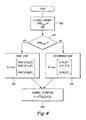
- step 400 indicates that if the receiver only possesses a single antenna, i.e., is a single branch receiver, then trace synchronization will be used and Sync Flag is set equal to zero.
- step 410 the input variable SynC Flag is evaluated to determine if trace or determinant synchronization shall be used. If the value of Sync Flag is 0, then trace synchronization is used and the flow proceeds to step 420. If, on the other hand, the value Sync Flag is not zero, then determinant synchronization is used and the flow proceeds to step 430. In addition to setting Sync Flag equal to zero at step 400 for single branch receivers, this process permits multibranch receivers to use either trace synchronization or determinant synchronization, e.g., by an initialization program which sets the value of Sync Flag outside of the flow depicted in Figure 4 .
- N o n f +m ⁇ , where m ⁇ is determined using either trace or determinant synchronization as reflected by Figure 4 .
- the computational complexity associated with determinant synchronization can be reduced by reusing calculations between different synchronization positions.
- Either estimating a synchronization position or estimating the number of channel taps can be performed first.
- Each synchronization step can be performed using a selected one of either trace or determinant based techniques, independently of the other synchronization steps.
- the synchronization steps includes, but are in general not limited to, trace and determinant techniques.
- determinant synchronization which, among other things, shall improve the performance of receivers' equalizers or detectors in terms of reduced bit errors and fewer block errors.
- predetermined matrix factorization e.g., Cholesky factorizations
- the sampling rate is a multiple, U, of the symbol rate.
- U the number of symbols rate.
Landscapes
- Engineering & Computer Science (AREA)
- Computer Networks & Wireless Communication (AREA)
- Signal Processing (AREA)
- Power Engineering (AREA)
- Synchronisation In Digital Transmission Systems (AREA)
- Mobile Radio Communication Systems (AREA)
- Radio Relay Systems (AREA)
- Stereo-Broadcasting Methods (AREA)
- Radio Transmission System (AREA)
Claims (23)
- Procédé destiné à traiter un signal reçu en utilisant un nombre variable de dérivations de canal, comprenant les étapes ci-après consistant à :(a) estimer une position de synchronisation préliminaire, dans lequel ladite étape d'estimation comprend les étapes ci-après consistant à :calculer des valeurs pour déterminer des éléments d'une matrice de covariance du bruit pour une première position de synchronisation ; etréutiliser lesdites valeurs afin de déterminer des éléments de ladite matrice de covariance du bruit pour une seconde position de synchronisation ;(b) utiliser ladite position de synchronisation préliminaire pour déterminer un nombre de dérivations de canal à utiliser pour traiter ledit signal reçu ;(c) déterminer une position de synchronisation sur la base dudit nombre déterminé de dérivations de canal ; et(d) calculer une estimation de canal en utilisant le nombre déterminé de dérivations de canal et la position de synchronisation déterminée.
- Procédé selon la revendication 1, comprenant en outre l'étape ci-après consistant à : répéter au moins l'une des étapes (b) et (c) avant de mettre en oeuvre l'étape (d).
- Procédé selon la revendication 1, comprenant en outre l'étape ci-après consistant à
stocker des résultats sélectionnés de ladite étape d'estimation d'une position de synchronisation préliminaire en vue d'une réutilisation subséquente. - Procédé selon la revendication 1, dans lequel ladite étape d'estimation de ladite position de synchronisation préliminaire est basée sur un plus grand nombre de dérivations de canal.
- Procédé selon la revendication 3, dans lequel ladite étape d'estimation de ladite position de synchronisation préliminaire comprend en outre l'étape ci-après consistant à :utiliser la trace des matrices de covariance du bruit.
- Procédé selon la revendication 6, comprenant en outre l'étape ci-après consistant à
sélectionner, au titre de ladite position de synchronisation préliminaire, une position de synchronisation qui s'associe à la plus petite valeur de trace desdites matrices de covariance du bruit. - Procédé selon la revendication 1, dans lequel lesdites valeurs sont des éléments d'une matrice de corrélation croisée entre ledit signal reçu et des symboles de synchronisation.
- Procédé selon la revendication 1, dans lequel lesdites valeurs sont des éléments d'une matrice d'autocorrélation dudit signal reçu.
- Procédé selon la revendication 1, dans lequel l'étape (b) comprend en outre l'étape ci-après consistant à :déterminer ledit nombre de dérivations de canal en utilisant l'opérateur de trace.
- Procédé selon la revendication 1, dans lequel l'étape (b) comprend en outre les étapes ci-après consistant à :calculer, pour une position de synchronisation prédéterminée et un nombre prédéterminé de dérivations de canal, au moins une valeur, sous la forme d'un décalage d'une valeur stockée, pour déterminer des éléments d'une matrice de covariance du bruit.
- Procédé selon la revendication 10, dans lequel ladite au moins une valeur est un élément d'une matrice de corrélation croisée entre ledit signal reçu et des symboles de synchronisation.
- Procédé selon la revendication 10, dans lequel ladite au moins une valeur est un élément d'une matrice d'autocorrélation dudit signal reçu.
- Procédé selon la revendication 1, dans lequel l'étape (c) comprend en outre l'étape ci-après consistant à :utiliser une synchronisation de trace ou une synchronisation de déterminant pour déterminer ladite position de synchronisation sur la base d'un nombre de branches associées audit signal reçu.
- Procédé selon la revendication 1, dans lequel l'étape (c) comprend en outre l'étape ci-après consistant à :utiliser un déterminant pour identifier ladite position de synchronisation.
- Procédé selon la revendication 14, comprenant en outre l'étape consistant à employer deux branches et dans lequel ledit déterminant est représenté par l'équation :

où m est une position de synchronisation, p concerne un nombre de dérivations de canal L(p)+1 et Q désigne une matrice de covariance du bruit. - Procédé selon la revendication 14, dans lequel l'étape (c) comprend en outre l'étape ci-après consistant à :calculer, pour une position de synchronisation prédéterminée, au moins une valeur au titre de décalage d'une valeur stockée, en vue de déterminer des éléments d'une matrice de covariance du bruit.
- Procédé selon la revendication 16, dans lequel ladite au moins une valeur est un élément d'une matrice d'autocorrélation dudit signal reçu.
- Procédé selon la revendication 1, comprenant en outre l'étape ci-après consistant à
stocker des résultats sélectionnés de l'étape (a) pour une réutilisation subséquente dans au moins l'une des étapes (c) à (d). - Procédé selon la revendication 18, dans lequel lesdits résultats sélectionnés comprennent au moins l'un parmi : des éléments de matrice de covariance du bruit, des éléments de matrice de corrélation croisée et des éléments de matrice d'autocorrélation.
- Procédé selon la revendication 1, dans lequel au moins l'une des étapes (b) à (d) comporte l'étape consistant à calculer des matrices de covariance du bruit associées audit signal reçu.
- Procédé selon la revendication 20, comprenant en outre l'étape de factorisation matricielle d'au moins une matrice intervenant dans le calcul desdites matrices de covariance du bruit en vue d'une réduction de la complexité de calcul informatique.
- Procédé selon la revendication 25, dans lequel ladite factorisation matricielle est une factorisation de Cholesky.
- Procédé selon la revendication 21, dans lequel ladite au moins une matrice est une matrice d'une séquence d'apprentissage associée audit signal reçu.
Applications Claiming Priority (3)
| Application Number | Priority Date | Filing Date | Title |
|---|---|---|---|
| US717007 | 2000-11-22 | ||
| US09/717,007 US6847690B1 (en) | 2000-11-22 | 2000-11-22 | Determinant-based synchronization techniques and systems |
| PCT/SE2001/002528 WO2002043270A2 (fr) | 2000-11-22 | 2001-11-13 | Systemes et techniques de synchronisation basee sur un facteur determinant |
Publications (2)
| Publication Number | Publication Date |
|---|---|
| EP1336261A2 EP1336261A2 (fr) | 2003-08-20 |
| EP1336261B1 true EP1336261B1 (fr) | 2010-09-08 |
Family
ID=24880343
Family Applications (1)
| Application Number | Title | Priority Date | Filing Date |
|---|---|---|---|
| EP01983054A Expired - Lifetime EP1336261B1 (fr) | 2000-11-22 | 2001-11-13 | Systemes et techniques de synchronisation basee sur un facteur determinant |
Country Status (6)
| Country | Link |
|---|---|
| US (1) | US6847690B1 (fr) |
| EP (1) | EP1336261B1 (fr) |
| AT (1) | ATE480911T1 (fr) |
| AU (1) | AU2002214509A1 (fr) |
| DE (1) | DE60143050D1 (fr) |
| WO (1) | WO2002043270A2 (fr) |
Families Citing this family (8)
| Publication number | Priority date | Publication date | Assignee | Title |
|---|---|---|---|---|
| US7394873B2 (en) * | 2002-12-18 | 2008-07-01 | Intel Corporation | Adaptive channel estimation for orthogonal frequency division multiplexing systems or the like |
| EP1531590A1 (fr) * | 2003-11-11 | 2005-05-18 | STMicroelectronics Belgium N.V. | Procédé et appareil pour l'égalisation de canaux avec estimation de la longueur de la réponse impulsionnelle du canal |
| DE102004005047B3 (de) * | 2004-01-30 | 2005-10-20 | Kronotec Ag | Verfahren und Einrichtung zum Einbringen eines die Feder einer Platte bildenden Streifens |
| US8000420B2 (en) * | 2005-06-24 | 2011-08-16 | Telefonaktiebolaget L M Ericsson (Publ) | System and method of joint synchronization and noise covariance estimation |
| CN109150364B (zh) * | 2017-06-28 | 2020-01-31 | 展讯通信(上海)有限公司 | 移动终端及其干扰噪声估计方法、计算机可读存储介质 |
| WO2022008372A1 (fr) * | 2020-07-10 | 2022-01-13 | Telefonaktiebolaget Lm Ericsson (Publ) | Opérations de coexistence basées sur réseau impliquant un équipement utilisateur activé par radar |
| EP4376538A3 (fr) | 2020-07-10 | 2024-09-04 | Telefonaktiebolaget LM Ericsson (publ) | Opérations de coexistence impliquant un équipement utilisateur et des n uds de réseau radio activés par radar |
| JP7510563B2 (ja) * | 2020-07-10 | 2024-07-03 | テレフオンアクチーボラゲット エルエム エリクソン(パブル) | レーダ対応ユーザ機器と他のユーザ機器との共存動作 |
Family Cites Families (10)
| Publication number | Priority date | Publication date | Assignee | Title |
|---|---|---|---|---|
| SE465597B (sv) | 1990-02-16 | 1991-09-30 | Ericsson Telefon Ab L M | Foerfarande att reducera inverkan av faedning hos en viterbimottagare med minst tvaa antenner |
| SE469678B (sv) | 1992-01-13 | 1993-08-16 | Ericsson Telefon Ab L M | Saett foer synkronisering och kanalestimering i tdma- radiosystem |
| US5581580A (en) | 1993-05-20 | 1996-12-03 | Telefonaktiebolaget Lm Ericsson | Low complexity model based channel estimation algorithm for fading channels |
| US5680419A (en) | 1994-08-02 | 1997-10-21 | Ericsson Inc. | Method of and apparatus for interference rejection combining in multi-antenna digital cellular communications systems |
| US5706314A (en) | 1995-01-04 | 1998-01-06 | Hughes Electronics | Joint maximum likelihood channel and timing error estimation |
| JP3013763B2 (ja) | 1995-08-25 | 2000-02-28 | 日本電気株式会社 | キャリア同期ユニット |
| US6084862A (en) * | 1997-09-26 | 2000-07-04 | Telefonaktiebolaget Lm Ericsson | Time dispersion measurement in radio communications systems |
| US6449320B1 (en) * | 1999-07-02 | 2002-09-10 | Telefonaktiebolaget Lm Ericsson (Publ) | Equalization with DC-offset compensation |
| MY133723A (en) | 1999-09-17 | 2007-11-30 | Ericsson Telefon Ab L M | "apparatus and method for substantially eliminating a near-channel interfering amplitude modulated signal" |
| US6603823B1 (en) * | 1999-11-12 | 2003-08-05 | Intel Corporation | Channel estimator |
-
2000
- 2000-11-22 US US09/717,007 patent/US6847690B1/en not_active Expired - Fee Related
-
2001
- 2001-11-13 DE DE60143050T patent/DE60143050D1/de not_active Expired - Lifetime
- 2001-11-13 AU AU2002214509A patent/AU2002214509A1/en not_active Abandoned
- 2001-11-13 EP EP01983054A patent/EP1336261B1/fr not_active Expired - Lifetime
- 2001-11-13 WO PCT/SE2001/002528 patent/WO2002043270A2/fr not_active Ceased
- 2001-11-13 AT AT01983054T patent/ATE480911T1/de not_active IP Right Cessation
Also Published As
| Publication number | Publication date |
|---|---|
| US6847690B1 (en) | 2005-01-25 |
| EP1336261A2 (fr) | 2003-08-20 |
| DE60143050D1 (de) | 2010-10-21 |
| WO2002043270A3 (fr) | 2002-07-18 |
| ATE480911T1 (de) | 2010-09-15 |
| AU2002214509A1 (en) | 2002-06-03 |
| WO2002043270A2 (fr) | 2002-05-30 |
Similar Documents
| Publication | Publication Date | Title |
|---|---|---|
| EP1205007B1 (fr) | Procede et appareil de reduction et de combinaison de faisceaux dans un systeme de radiocommunication | |
| US6314147B1 (en) | Two-stage CCI/ISI reduction with space-time processing in TDMA cellular networks | |
| AU691953B2 (en) | Method of and apparatus for interference rejection combining in multi-antenna digital cellular communications systems | |
| US6173014B1 (en) | Method of and apparatus for interference rejection combining and downlink beamforming in a cellular radio communications system | |
| EP0988729B1 (fr) | Procede et systeme permettant de determiner le rapport puissance de signal/puissance de l'interference plus bruit (sinr) dans un systeme de communication | |
| EP0894367B1 (fr) | Procede et appareil de rejet d'interferences avec differents faisceaux, polarisations et references de phase | |
| US5875216A (en) | Weight generation in stationary interference and noise environments | |
| US7949304B2 (en) | Interference cancellation and receive diversity for single-valued modulation receivers | |
| CN100393139C (zh) | 不断变化的干扰环境中形成波束的设备和方法 | |
| JP4343694B2 (ja) | 送信チャネル間のゲインオフセットを決定する方法 | |
| US8150326B2 (en) | Signal processing for multi-sectored wireless communications system and method thereof | |
| US6901122B2 (en) | Method and apparatus for restoring a soft decision component of a signal | |
| TWI479827B (zh) | 具接收分集之無線接收器 | |
| US5796788A (en) | Method and apparatus for interference decorrelation in time and space | |
| US6147985A (en) | Subspace method for adaptive array weight tracking | |
| EP2514155B1 (fr) | Estimation hybride du canal de tranmission en utilisant des techniques de corrélation et la méthode des moindres carrés | |
| EP1499037A1 (fr) | Dispositif et procédé pour recevoir des données dans un système de communication mobile utilisant un schéma de réseau d'antennes adaptives | |
| WO1999001950A2 (fr) | Interpretation d'un signal reçu | |
| US8121565B2 (en) | Method and apparatus for receiving data using multiple antennas in a communication system | |
| EP1336261B1 (fr) | Systemes et techniques de synchronisation basee sur un facteur determinant | |
| US8913700B1 (en) | High-performance diagonal loading for MMSE equalization | |
| US9344303B1 (en) | Adaptive signal covariance estimation for MMSE equalization | |
| JP2002204192A (ja) | 受信方法及び受信機 | |
| US7310538B2 (en) | Symbol estimation-based decorrelator for directing beams and nulls to remote users in a wireless communications system | |
| US6950630B2 (en) | Hard decision-based decorrelator for estimating spatial signatures in a wireless communications system |
Legal Events
| Date | Code | Title | Description |
|---|---|---|---|
| PUAI | Public reference made under article 153(3) epc to a published international application that has entered the european phase |
Free format text: ORIGINAL CODE: 0009012 |
|
| 17P | Request for examination filed |
Effective date: 20030325 |
|
| AK | Designated contracting states |
Designated state(s): AT BE CH CY DE DK ES FI FR GB GR IE IT LI LU MC NL PT SE TR |
|
| AX | Request for extension of the european patent |
Extension state: AL LT LV MK RO SI |
|
| RAP1 | Party data changed (applicant data changed or rights of an application transferred) |
Owner name: TELEFONAKTIEBOLAGET LM ERICSSON (PUBL) |
|
| 17Q | First examination report despatched |
Effective date: 20061222 |
|
| GRAP | Despatch of communication of intention to grant a patent |
Free format text: ORIGINAL CODE: EPIDOSNIGR1 |
|
| GRAS | Grant fee paid |
Free format text: ORIGINAL CODE: EPIDOSNIGR3 |
|
| GRAA | (expected) grant |
Free format text: ORIGINAL CODE: 0009210 |
|
| AK | Designated contracting states |
Kind code of ref document: B1 Designated state(s): AT BE CH CY DE DK ES FI FR GB GR IE IT LI LU MC NL PT SE TR |
|
| REG | Reference to a national code |
Ref country code: GB Ref legal event code: FG4D |
|
| REG | Reference to a national code |
Ref country code: CH Ref legal event code: EP |
|
| REG | Reference to a national code |
Ref country code: IE Ref legal event code: FG4D |
|
| REF | Corresponds to: |
Ref document number: 60143050 Country of ref document: DE Date of ref document: 20101021 Kind code of ref document: P |
|
| REG | Reference to a national code |
Ref country code: NL Ref legal event code: T3 |
|
| PG25 | Lapsed in a contracting state [announced via postgrant information from national office to epo] |
Ref country code: AT Free format text: LAPSE BECAUSE OF FAILURE TO SUBMIT A TRANSLATION OF THE DESCRIPTION OR TO PAY THE FEE WITHIN THE PRESCRIBED TIME-LIMIT Effective date: 20100908 Ref country code: FI Free format text: LAPSE BECAUSE OF FAILURE TO SUBMIT A TRANSLATION OF THE DESCRIPTION OR TO PAY THE FEE WITHIN THE PRESCRIBED TIME-LIMIT Effective date: 20100908 |
|
| PG25 | Lapsed in a contracting state [announced via postgrant information from national office to epo] |
Ref country code: CY Free format text: LAPSE BECAUSE OF FAILURE TO SUBMIT A TRANSLATION OF THE DESCRIPTION OR TO PAY THE FEE WITHIN THE PRESCRIBED TIME-LIMIT Effective date: 20100908 |
|
| PG25 | Lapsed in a contracting state [announced via postgrant information from national office to epo] |
Ref country code: SE Free format text: LAPSE BECAUSE OF FAILURE TO SUBMIT A TRANSLATION OF THE DESCRIPTION OR TO PAY THE FEE WITHIN THE PRESCRIBED TIME-LIMIT Effective date: 20100908 Ref country code: GR Free format text: LAPSE BECAUSE OF FAILURE TO SUBMIT A TRANSLATION OF THE DESCRIPTION OR TO PAY THE FEE WITHIN THE PRESCRIBED TIME-LIMIT Effective date: 20101209 |
|
| PG25 | Lapsed in a contracting state [announced via postgrant information from national office to epo] |
Ref country code: PT Free format text: LAPSE BECAUSE OF FAILURE TO SUBMIT A TRANSLATION OF THE DESCRIPTION OR TO PAY THE FEE WITHIN THE PRESCRIBED TIME-LIMIT Effective date: 20110110 Ref country code: IT Free format text: LAPSE BECAUSE OF FAILURE TO SUBMIT A TRANSLATION OF THE DESCRIPTION OR TO PAY THE FEE WITHIN THE PRESCRIBED TIME-LIMIT Effective date: 20100908 |
|
| PG25 | Lapsed in a contracting state [announced via postgrant information from national office to epo] |
Ref country code: MC Free format text: LAPSE BECAUSE OF NON-PAYMENT OF DUE FEES Effective date: 20101130 Ref country code: ES Free format text: LAPSE BECAUSE OF FAILURE TO SUBMIT A TRANSLATION OF THE DESCRIPTION OR TO PAY THE FEE WITHIN THE PRESCRIBED TIME-LIMIT Effective date: 20101219 Ref country code: BE Free format text: LAPSE BECAUSE OF FAILURE TO SUBMIT A TRANSLATION OF THE DESCRIPTION OR TO PAY THE FEE WITHIN THE PRESCRIBED TIME-LIMIT Effective date: 20100908 |
|
| REG | Reference to a national code |
Ref country code: CH Ref legal event code: PL |
|
| PLBE | No opposition filed within time limit |
Free format text: ORIGINAL CODE: 0009261 |
|
| STAA | Information on the status of an ep patent application or granted ep patent |
Free format text: STATUS: NO OPPOSITION FILED WITHIN TIME LIMIT |
|
| PG25 | Lapsed in a contracting state [announced via postgrant information from national office to epo] |
Ref country code: CH Free format text: LAPSE BECAUSE OF NON-PAYMENT OF DUE FEES Effective date: 20101130 Ref country code: LI Free format text: LAPSE BECAUSE OF NON-PAYMENT OF DUE FEES Effective date: 20101130 |
|
| 26N | No opposition filed |
Effective date: 20110609 |
|
| REG | Reference to a national code |
Ref country code: FR Ref legal event code: ST Effective date: 20110801 |
|
| PG25 | Lapsed in a contracting state [announced via postgrant information from national office to epo] |
Ref country code: DK Free format text: LAPSE BECAUSE OF FAILURE TO SUBMIT A TRANSLATION OF THE DESCRIPTION OR TO PAY THE FEE WITHIN THE PRESCRIBED TIME-LIMIT Effective date: 20100908 |
|
| REG | Reference to a national code |
Ref country code: DE Ref legal event code: R097 Ref document number: 60143050 Country of ref document: DE Effective date: 20110609 |
|
| PG25 | Lapsed in a contracting state [announced via postgrant information from national office to epo] |
Ref country code: IE Free format text: LAPSE BECAUSE OF NON-PAYMENT OF DUE FEES Effective date: 20101113 Ref country code: FR Free format text: LAPSE BECAUSE OF NON-PAYMENT OF DUE FEES Effective date: 20101130 |
|
| PG25 | Lapsed in a contracting state [announced via postgrant information from national office to epo] |
Ref country code: LU Free format text: LAPSE BECAUSE OF NON-PAYMENT OF DUE FEES Effective date: 20101113 |
|
| PG25 | Lapsed in a contracting state [announced via postgrant information from national office to epo] |
Ref country code: TR Free format text: LAPSE BECAUSE OF FAILURE TO SUBMIT A TRANSLATION OF THE DESCRIPTION OR TO PAY THE FEE WITHIN THE PRESCRIBED TIME-LIMIT Effective date: 20100908 |
|
| PGFP | Annual fee paid to national office [announced via postgrant information from national office to epo] |
Ref country code: GB Payment date: 20141127 Year of fee payment: 14 Ref country code: DE Payment date: 20141128 Year of fee payment: 14 |
|
| PGFP | Annual fee paid to national office [announced via postgrant information from national office to epo] |
Ref country code: NL Payment date: 20151126 Year of fee payment: 15 |
|
| REG | Reference to a national code |
Ref country code: DE Ref legal event code: R119 Ref document number: 60143050 Country of ref document: DE |
|
| GBPC | Gb: european patent ceased through non-payment of renewal fee |
Effective date: 20151113 |
|
| PG25 | Lapsed in a contracting state [announced via postgrant information from national office to epo] |
Ref country code: GB Free format text: LAPSE BECAUSE OF NON-PAYMENT OF DUE FEES Effective date: 20151113 Ref country code: DE Free format text: LAPSE BECAUSE OF NON-PAYMENT OF DUE FEES Effective date: 20160601 |
|
| REG | Reference to a national code |
Ref country code: NL Ref legal event code: MM Effective date: 20161201 |
|
| PG25 | Lapsed in a contracting state [announced via postgrant information from national office to epo] |
Ref country code: NL Free format text: LAPSE BECAUSE OF NON-PAYMENT OF DUE FEES Effective date: 20161201 |