EP1336454A1 - Procédé et dispositif d'usinage par bande abrasive d'une surface de portée sur une pièce, notamment pour la superfinition d'une surface de came sur un arbre à cames - Google Patents
Procédé et dispositif d'usinage par bande abrasive d'une surface de portée sur une pièce, notamment pour la superfinition d'une surface de came sur un arbre à cames Download PDFInfo
- Publication number
- EP1336454A1 EP1336454A1 EP03290276A EP03290276A EP1336454A1 EP 1336454 A1 EP1336454 A1 EP 1336454A1 EP 03290276 A EP03290276 A EP 03290276A EP 03290276 A EP03290276 A EP 03290276A EP 1336454 A1 EP1336454 A1 EP 1336454A1
- Authority
- EP
- European Patent Office
- Prior art keywords
- support
- abrasive
- strip
- axis
- rotation
- Prior art date
- Legal status (The legal status is an assumption and is not a legal conclusion. Google has not performed a legal analysis and makes no representation as to the accuracy of the status listed.)
- Granted
Links
- 238000000034 method Methods 0.000 title claims description 10
- 238000003754 machining Methods 0.000 claims abstract description 39
- 239000012530 fluid Substances 0.000 claims description 5
- 238000006073 displacement reaction Methods 0.000 description 1
- 230000000694 effects Effects 0.000 description 1
- 230000003370 grooming effect Effects 0.000 description 1
- 210000000056 organ Anatomy 0.000 description 1
- 238000004804 winding Methods 0.000 description 1
Images







Classifications
-
- B—PERFORMING OPERATIONS; TRANSPORTING
- B24—GRINDING; POLISHING
- B24B—MACHINES, DEVICES, OR PROCESSES FOR GRINDING OR POLISHING; DRESSING OR CONDITIONING OF ABRADING SURFACES; FEEDING OF GRINDING, POLISHING, OR LAPPING AGENTS
- B24B49/00—Measuring or gauging equipment for controlling the feed movement of the grinding tool or work; Arrangements of indicating or measuring equipment, e.g. for indicating the start of the grinding operation
- B24B49/16—Measuring or gauging equipment for controlling the feed movement of the grinding tool or work; Arrangements of indicating or measuring equipment, e.g. for indicating the start of the grinding operation taking regard of the load
-
- B—PERFORMING OPERATIONS; TRANSPORTING
- B24—GRINDING; POLISHING
- B24B—MACHINES, DEVICES, OR PROCESSES FOR GRINDING OR POLISHING; DRESSING OR CONDITIONING OF ABRADING SURFACES; FEEDING OF GRINDING, POLISHING, OR LAPPING AGENTS
- B24B19/00—Single-purpose machines or devices for particular grinding operations not covered by any other main group
- B24B19/08—Single-purpose machines or devices for particular grinding operations not covered by any other main group for grinding non-circular cross-sections, e.g. shafts of elliptical or polygonal cross-section
- B24B19/12—Single-purpose machines or devices for particular grinding operations not covered by any other main group for grinding non-circular cross-sections, e.g. shafts of elliptical or polygonal cross-section for grinding cams or camshafts
-
- B—PERFORMING OPERATIONS; TRANSPORTING
- B24—GRINDING; POLISHING
- B24B—MACHINES, DEVICES, OR PROCESSES FOR GRINDING OR POLISHING; DRESSING OR CONDITIONING OF ABRADING SURFACES; FEEDING OF GRINDING, POLISHING, OR LAPPING AGENTS
- B24B21/00—Machines or devices using grinding or polishing belts; Accessories therefor
- B24B21/004—Machines or devices using grinding or polishing belts; Accessories therefor using abrasive rolled strips
Definitions
- the present invention relates to a method and a abrasive belt machining device, on a workpiece having an axis of rotation, of at least one non-cylindrical bearing surface, in particular for superfinishing a cam surface on a camshaft.
- Abrasive belt superfinishing commonly known as superfinishing by "grooming" cam surfaces on trees with cams can be carried out, the camshaft being mounted between points and driven in rotation around its axis, by applying a band abrasive running against a cam surface using a roller of support pushed by a jack against said cam surface. He is coming however, the same portion of abrasive tape is then applied, in the area of the top of the cam, twice successively against the same surface, namely first in new condition against a first flank of the cam and then in the "worn” state against a second flank of the same cam, which does not give the cam surface a quality machining (surface condition) well defined at all points of the circumference.
- the present invention relates to a strip machining process abrasive to improve speed, quality and consistency for machining non-cylindrical bearing surfaces and in particular for cam surfaces.
- the invention further relates to a machining process by abrasive band allowing to modulate the pressures at will of the abrasive belt.
- the invention also relates to a device abrasive belt machining which is simple in structure and allows to machine non-cylindrical bearing surfaces at a reduced cost at a high speed and with high quality and regularity of machining.
- the process which is the subject of the invention is intended for machining by abrasive belt, on a part having an axis of rotation, of a surface of non-cylindrical bearing, in particular of a cam surface on a camshaft.
- This process includes a machining cycle consisting of applying an abrasive strip by means of support along an area substantially linear contact, parallel to the axis of rotation of the part, against the bearing surface while the part is driven in rotation around its axis of rotation, and to scroll the strip abrasive in its longitudinal direction on the bearing means during machining.
- two portions of the same are applied strip running that are spaced apart from each other in the direction longitudinal of the strip, using two support members independent, following two angularly spaced contact zones around the axis of rotation of the part, against the bearing surface.
- the abrasive belt to allow to obtain the same machining efficiency in each of the two support members, and for optimal use of the abrasive belt single, it is possible to advance the abrasive belt, between two successive machining cycles of a corresponding length substantially at the running length of the strip during each machining cycle, and deflect the abrasive belt between the two bodies support in the form of a length loop such that at each cycle machining, the second support member also receives and applies a portion of new abrasive tape against the bearing surface.
- the device which is the subject of the invention used for implementation of the above process includes means for supporting the workpiece and to drive it in rotation about its axis, support means for apply at least one abrasive strip against at least one surface of scope of the workpiece, and means for guiding and driving the abrasive strip for running the abrasive strip in its direction longitudinal on the support means.
- the means support include two support units mounted on a support common and each having a movable support member perpendicular to the axis of rotation of the part regardless of that of the other support unit.
- Guidance and training means are designed to scroll the same abrasive belt successively on the two support members.
- the two support units can each understand for example a spring or other non controlled allowing to exert a bearing force on the bearing member associated.
- the common support should preferably be movable transversely to the part before and after each machining cycle.
- the two support units each include a fluid cylinder, cylinders two cylinders being mounted on the same support in such a way that the axes of the piston rods carrying the support members intersect on the axis of rotation of the part.
- the common support can be stationary, the only control of the cylinders then allowing also to obtain the necessary displacements of the support members relative to the surface area before and after each cycle machining.
- the cylinders allow precise definition of the support force and in particular to keep it constant over the whole circumference of the bearing surface, which is not the case when the use of springs or the like
- the two cylinders can be ordered separately, which allows to modulate at will the force and the duration of support of the band abrasive against the bearing surface by each support member.
- the support can also carry a return roller on which the abrasive belt is deflected by being guided transversely between the two support rollers. This allows the abrasive belt which is not guided transversely to its length at the level of the two rollers support to better follow the beat movements along the axis of the piece, movements which are essential in super-finishing, such as this is well known in itself.
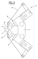
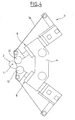
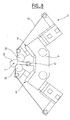
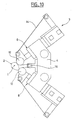
- a camshaft 1 symbolized by its axis of rotation is mounted between points and rotated around its axis which is here horizontal for the machining (superfinishing) of a cam surface 2 by a device 3 arranged on one side of the shaft to cams 1, substantially in the plane of the (surface of) cam 2 to be machined.
- the device 3 comprises a support 4 mounted, by means not shown, adjustable (arrow 5) in position relative to the camshaft 1, in a direction perpendicular to the axis of this latest.
- the support 4 which is symmetrical with respect to a plane 6 passing through the axis of the camshaft 1 can also be adjustable in position parallel to the axis of the camshaft 1 by means of guide which can for example be sockets 7 movable on slides.
- the support 4 carries, in the same plane perpendicular to its plane of symmetry 6, in positions symmetrical with respect to this plane 6, two fluid cylinders 8, for example two pneumatic cylinders with double effect, the cylinders 9 of which are integral with the support 4 of so that the axes of the piston rods 10 intersect on the axis of rotation of the camshaft 1.
- Each piston rod 10 carries its free end a mount 11 on which a support roller 12 and a guide roller 13 are mounted in the same plane while being movable rotating around axes parallel to the axis of the camshaft 1.
- the support rollers 12 are located in the extension of the piston rods 10 and the guide rollers 13 are offset one up and the other down relative to the support rollers 12, respectively.
- a abrasive belt 14 passes from a new reel of tape not shown by a first deflection roller 15 on a first guide roller 13, then successively on the two support rollers 12 which apply it against the cam surface 2, to return via the second roller guide 13 on a second idler roller 15 and from there on a reel not shown rewinding of worn tape.
- a system drive not shown, controlled, allows to advance, therefore to scroll the abrasive strip 14 at will.
- the two support rollers 12, under the action of the two jacks 8, thus apply the same abrasive strip 14 against the cam surface 2 along two substantially linear contact zones, parallel to the axis of the camshaft 1 and angularly spaced around this axis, while the camshaft 1 is rotated around its axis and that the abrasive belt 14 is driven in its direction longitudinal to scroll on the support rollers 12.
- the cylinders 8 controlling the support rollers 12 allow the strip to be applied abrasive 14, in each of the two contact zones defined by the two rollers 12, permanently against the cam surface 2 with a force which is a function only of the supply pressure in fluid of each cylinder.
- This bearing force therefore does not vary with the radial distance of the support rollers 12 relative to the axis of rotation, which, when machining a cam surface on a camshaft, varies during rotation of the camshaft around its axis.
- abrasive strip 14 against the cam surface 2 with different pressures and / or for different durations by both support rollers 12 during each machining cycle. This result can be obtained in a simple manner on the device as shown and described by a corresponding individual power control in fluid from each of the two cylinders 8.
- the device 3 as illustrated in FIGS. 7 to 12 continues all the general structural characteristics of the following device 3 Figures 1 to 6, but further comprises, on the support 4, between the two cylinders 8, a guide and guide roller 16 on which the strip abrasive 14 passes between the two support rollers 12, being deflected and transversely guided.
- the abrasive belt 14 which is not guided laterally on the support rollers 12 devoid of guide flanges thus participates better in the beat movements printed at the entire machining device 3, as is usual in superfinishing, transverse to the length of the abrasive strip 14, therefore, parallel to the axis of the camshaft 1.
- the idler roller 16 imposes on the strip 14, between the two support rollers 12, an additional loop-shaped path, of a preferably adjustable length which depends on the position or distance from the roller 16 relative to the support rollers 12.
- the two jacks 8 are mounted on the support 4 so that the axes of their rods piston 10 which cross on the axis of rotation of the camshaft 1 make an angle with each other that is slightly less than 90 °. This angle can however be different, insofar as it remains less than 180 °.
- the two jacks 8 could be replaced by other means producing the bearing pressures of the rollers 12 against the cam surface 2, for example by springs, but the advantage essential of the cylinders 8 is that they can be ordered at will, this which allows, for example, to modulate the support pressures and the support times of the two rollers 12 and of moving the two rollers 12 before and after each machining cycle using only support cylinders 8 to engage the abrasive strip 14 with and disengage it from the surface of cam 2, without moving the support 4 away from the camshaft 1 according to the arrow 5 visible in FIG. 1.
- the invention makes it possible, with a single abrasive belt and a single support and sliding system d e this abrasive belt, a machining result equivalent to that provided by two abrasive belts and two support and running systems of these two bands
Landscapes
- Engineering & Computer Science (AREA)
- Mechanical Engineering (AREA)
- Finish Polishing, Edge Sharpening, And Grinding By Specific Grinding Devices (AREA)
- Grinding And Polishing Of Tertiary Curved Surfaces And Surfaces With Complex Shapes (AREA)
Abstract
Description
Claims (9)
- Procédé d'usinage par bande abrasive, sur une pièce ayant un axe de rotation, d'une surface de portée non cylindrique, notamment d'une surface de came sur un arbre à cames, comprenant un cycle d'usinage consistant à appliquer une bande abrasive par des moyens d'appui suivant une zone de contact sensiblement linéaire, parallèle à l'axe de rotation de la pièce, contre la surface de portée pendant que la pièce est entraínée en rotation autour de son axe de rotation, et à faire défiler la bande abrasive dans sa direction longitudinal sur les moyens d'appui pendant l'usinage, caractérisé par le fait qu'on applique deux portions de la même bande en défilement qui sont espacées l'une de l'autre dans la direction longitudinale de la bande, à l'aide de deux organes d'appui indépendants, suivant deux zones de contact angulairement espacées autour de l'axe de rotation de la pièce, contre la surface de portée.
- Procédé suivant la revendication 1, caractérisé par le fait qu'on applique les deux portions de la bande abrasive à l'aide des deux organes d'appui contre la surface de portée suivant deux directions d'action qui se croisent sur l'axe de rotation de la pièce.
- Procédé suivant la revendication 2, caractérisé par le fait qu'on applique les deux portions de la bande abrasive suivant deux directions d'action qui font l'une avec l'autre un angle inférieur à 180°.
- Procédé suivant la revendication 3, caractérisé par le fait qu'on applique les deux portions de la bande abrasive suivant deux directions d'action qui font l'une avec l'autre un angle inférieur à 120° et de préférence inférieur ou égal à 90°.
- Procédé suivant l'une quelconque des revendications précédentes, caractérisé par le fait qu'on fait avancer la bande abrasive, entre deux cycles d'usinage successifs, d'une longueur correspondant sensiblement à la longueur de défilement de la bande pendant chaque cycle d'usinage et qu'on dévie la bande abrasive entre les deux organes d'appui sous la forme d'une boucle de longueur telle qu'à chaque cycle d'usinage, le second organe d'appui reçoive et applique une portion de bande abrasive neuve contre la surface de portée.
- Dispositif pour l'usinage par bande abrasive, sur une pièce ayant un axe de rotation, d'une surface de portée non cylindrique, notamment d'une surface de came sur un arbre à cames, comprenant des moyens pour supporter la pièce et pour l'entraíner en rotation autour de son axe, des moyens d'appui pour appliquer au moins une bande abrasive contre au moins une surface de portée de la pièce, et des moyens de guidage et d'entraínement de la bande abrasive pour faire défiler la bande abrasive dans sa direction longitudinale sur les moyens d'appui, caractérisé par le fait que les moyens d'appui comprennent deux unités d'appui (8) montées sur un même support (4) et ayant chacune un galet d'appui (12) mobile perpendiculairement à l'axe de rotation de la pièce (1) indépendamment de celui de l'autre unité d'appui, et que les moyens (13, 15) de guidage et d'entraínement sont conçus pour faire défiler la même bande abrasive (14) successivement sur les deux organes d'appui (12).
- Dispositif suivant la revendication 6, caractérisé par le fait que les deux unités d'appui comprennent chacune un vérin à fluide (8), les cylindres (9) des deux vérins étant montés sur le support (4) de telle manière que les axes des tiges de piston (10) portant chacun un galet d'appui (12) se croisent sur l'axe de rotation de la pièce (1).
- Dispositif suivant la revendication 7, caractérisé par le fait que les deux vérins sont commandés séparément.
- Dispositif suivant l'une quelconque des revendications 6 à 8, caractérisé par le fait que le support (4) porte un galet de renvoi (16) sur lequel la bande abrasive (14) est déviée en étant guidée transversalement, entre les deux galets d'appui (12).
Applications Claiming Priority (2)
| Application Number | Priority Date | Filing Date | Title |
|---|---|---|---|
| FR0201315 | 2002-02-05 | ||
| FR0201315A FR2835460B1 (fr) | 2002-02-05 | 2002-02-05 | Procede et dispositif d'usinage par bande abrasive d'une surface de portee sur une piece, notamment pour la superfinition d'une surface de came sur un arbre a cames |
Publications (2)
| Publication Number | Publication Date |
|---|---|
| EP1336454A1 true EP1336454A1 (fr) | 2003-08-20 |
| EP1336454B1 EP1336454B1 (fr) | 2007-09-26 |
Family
ID=27619877
Family Applications (1)
| Application Number | Title | Priority Date | Filing Date |
|---|---|---|---|
| EP03290276A Expired - Lifetime EP1336454B1 (fr) | 2002-02-05 | 2003-02-04 | Procédé et dispositif d'usinage par bande abrasive d'une surface de portée sur une pièce, notamment pour la superfinition d'une surface de came sur un arbre à cames |
Country Status (4)
| Country | Link |
|---|---|
| US (1) | US6916230B2 (fr) |
| EP (1) | EP1336454B1 (fr) |
| DE (1) | DE60316485D1 (fr) |
| FR (1) | FR2835460B1 (fr) |
Cited By (2)
| Publication number | Priority date | Publication date | Assignee | Title |
|---|---|---|---|---|
| WO2008113925A1 (fr) * | 2007-03-21 | 2008-09-25 | Renault S.A.S. | Machoires asservies localement pour le toilage de portees |
| FR2952564A1 (fr) * | 2009-11-18 | 2011-05-20 | Snecma | Dispositif et procede de toilage a lacet automatise |
Families Citing this family (6)
| Publication number | Priority date | Publication date | Assignee | Title |
|---|---|---|---|---|
| DE102006052829A1 (de) * | 2006-11-09 | 2008-05-15 | Thielenhaus Technologies Gmbh | Verfahren zur Bandfinishbearbeitung von Werkstückenumfangsflächen |
| US7955163B2 (en) * | 2007-05-03 | 2011-06-07 | Combined Products Co. #1, Inc. | Abrading device |
| JP2009119548A (ja) * | 2007-11-14 | 2009-06-04 | Honda Motor Co Ltd | 軸部仕上げ加工装置 |
| JP5551395B2 (ja) * | 2009-08-28 | 2014-07-16 | マニー株式会社 | カニューレ及びその製造方法 |
| EP2823934B1 (fr) * | 2013-07-09 | 2015-02-18 | Supfina Grieshaber GmbH & Co. KG | Dispositif d'usinage de précision d'une surface périphérique de pièce et procédé de fonctionnement du dispositif |
| DE102015221939B4 (de) | 2015-11-09 | 2018-10-31 | Supfina Grieshaber Gmbh & Co. Kg | Finishbandvorrichtung und Verfahren zur finishenden Bearbeitung eines Werkstücks |
Citations (4)
| Publication number | Priority date | Publication date | Assignee | Title |
|---|---|---|---|---|
| US4945683A (en) * | 1989-07-10 | 1990-08-07 | J. D. Phillips Corporation | Abrasive belt grinding machine |
| US5536201A (en) * | 1993-06-24 | 1996-07-16 | Maschinenbau Griehaber Gmbh & Co. | Apparatus for surface machining |
| US5762542A (en) * | 1993-12-14 | 1998-06-09 | Grobi A/S | Edge grinder for mechanically rounding off edges of structural members |
| US6102783A (en) * | 1998-01-13 | 2000-08-15 | Ernst Thielenhaus Gmbh & Co. Kg | Apparatus for microfinishing cam-shaft surfaces |
Family Cites Families (4)
| Publication number | Priority date | Publication date | Assignee | Title |
|---|---|---|---|---|
| US5498444A (en) * | 1994-02-28 | 1996-03-12 | Microfab Technologies, Inc. | Method for producing micro-optical components |
| FR2719516B1 (fr) * | 1994-05-04 | 1996-07-26 | Procedes Machines Speciales | Outillage pour le toilage de portées cylindriques avec contrôle de diamètre des portées. |
| US5664991A (en) * | 1996-01-11 | 1997-09-09 | Barton, Ii; Kenneth A. | Microfinishing and roller burnishing machine |
| SE513311C2 (sv) * | 1998-12-29 | 2000-08-21 | Gustav Rennerfelt | Excenterväxel |
-
2002
- 2002-02-05 FR FR0201315A patent/FR2835460B1/fr not_active Expired - Fee Related
-
2003
- 2003-02-04 DE DE60316485T patent/DE60316485D1/de not_active Expired - Lifetime
- 2003-02-04 EP EP03290276A patent/EP1336454B1/fr not_active Expired - Lifetime
- 2003-02-05 US US10/358,261 patent/US6916230B2/en not_active Expired - Fee Related
Patent Citations (4)
| Publication number | Priority date | Publication date | Assignee | Title |
|---|---|---|---|---|
| US4945683A (en) * | 1989-07-10 | 1990-08-07 | J. D. Phillips Corporation | Abrasive belt grinding machine |
| US5536201A (en) * | 1993-06-24 | 1996-07-16 | Maschinenbau Griehaber Gmbh & Co. | Apparatus for surface machining |
| US5762542A (en) * | 1993-12-14 | 1998-06-09 | Grobi A/S | Edge grinder for mechanically rounding off edges of structural members |
| US6102783A (en) * | 1998-01-13 | 2000-08-15 | Ernst Thielenhaus Gmbh & Co. Kg | Apparatus for microfinishing cam-shaft surfaces |
Cited By (3)
| Publication number | Priority date | Publication date | Assignee | Title |
|---|---|---|---|---|
| WO2008113925A1 (fr) * | 2007-03-21 | 2008-09-25 | Renault S.A.S. | Machoires asservies localement pour le toilage de portees |
| FR2913904A1 (fr) * | 2007-03-21 | 2008-09-26 | Renault Sas | Machoires asservies localement pour le toilage de portees |
| FR2952564A1 (fr) * | 2009-11-18 | 2011-05-20 | Snecma | Dispositif et procede de toilage a lacet automatise |
Also Published As
| Publication number | Publication date |
|---|---|
| FR2835460B1 (fr) | 2004-07-23 |
| US6916230B2 (en) | 2005-07-12 |
| DE60316485D1 (de) | 2007-11-08 |
| EP1336454B1 (fr) | 2007-09-26 |
| FR2835460A1 (fr) | 2003-08-08 |
| US20040029499A1 (en) | 2004-02-12 |
Similar Documents
| Publication | Publication Date | Title |
|---|---|---|
| EP0428462B1 (fr) | Procédé de montage de roulements d'axes, en particulier de codeurs, dispositif pour la mise en oeuvre de ce procédé et codeurs ainsi obtenus | |
| CA2128564C (fr) | Dispositif de nettoyage d'un cylindre | |
| FR2649347A1 (fr) | Appareil de rectification des cames d'un arbre a cames | |
| EP1336454B1 (fr) | Procédé et dispositif d'usinage par bande abrasive d'une surface de portée sur une pièce, notamment pour la superfinition d'une surface de came sur un arbre à cames | |
| FR2790997A1 (fr) | Dispositif pour imprimer un signe et machine a affranchir le comportant | |
| CA2320861A1 (fr) | Dispositif autonome de pose de bandes | |
| FR2477513A1 (fr) | Dispositif deviateur pour bandes de papier en particulier | |
| FR2650529A1 (fr) | Dispositif applicateur pour machine de nappage au moyen de ruban de matiere composite | |
| FR2913904A1 (fr) | Machoires asservies localement pour le toilage de portees | |
| FR2513608A1 (fr) | Appareil de manutention de feuilles minces de materiau | |
| FR2864797A1 (fr) | Machine de planage d'une bande metallique | |
| EP1401746B1 (fr) | Dispositif de transport de pieces pour l'alimentation de machines | |
| FR2516846A1 (fr) | Appareil de decoupage d'une bande de materiau pour plaques d'accumulateur | |
| FR2745805A1 (fr) | Machine a derouler des bobines en continu comportant au moins un moyen de deroulage de deux bobines jumelees ou coaxiales simultanement | |
| EP0882549A1 (fr) | Machine d'usinage par bande abrasive de portées cylindriques d'arbres | |
| EP0850722A1 (fr) | Machine d'usinage par bande abrasive de surfaces internes de pièces de révolution | |
| FR2646627A1 (fr) | Derouleuse de troncs d'arbre avec dispositif antiflexion perfectionne | |
| EP0010016B1 (fr) | Mécanisme de commande du déplacement d'une règle mobile parallèlement à elle-même sur une planche à dessin | |
| FR2805768A1 (fr) | Procede de superfinition de pieces a surface cylindrique | |
| EP3053716B1 (fr) | Dispositif de decoupe rotative de matiere | |
| EP0434533A1 (fr) | Machine de superfinition pour des arbres, notamment des arbres à cames | |
| FR2814731A1 (fr) | Dispositif de raccordement de precision pour une machine a derouler en continu | |
| FR2876937A1 (fr) | Machine a polir des eprouvettes | |
| FR2825652A1 (fr) | Machine d'usinage par abrasif de portees d'une piece, notamment de superfinition de manetons de vilebrequins | |
| BE815807R (fr) | Dispositif destine a la fixation de l'extremite libre d'un rouleau de materiau audit rouleau |
Legal Events
| Date | Code | Title | Description |
|---|---|---|---|
| PUAI | Public reference made under article 153(3) epc to a published international application that has entered the european phase |
Free format text: ORIGINAL CODE: 0009012 |
|
| AK | Designated contracting states |
Designated state(s): AT BE BG CH CY CZ DE DK EE ES FI FR GB GR HU IE IT LI LU MC NL PT SE SI SK TR |
|
| AX | Request for extension of the european patent |
Extension state: AL LT LV MK RO |
|
| 17P | Request for examination filed |
Effective date: 20040220 |
|
| AKX | Designation fees paid |
Designated state(s): DE ES GB IT PT |
|
| 17Q | First examination report despatched |
Effective date: 20061206 |
|
| GRAP | Despatch of communication of intention to grant a patent |
Free format text: ORIGINAL CODE: EPIDOSNIGR1 |
|
| RTI1 | Title (correction) |
Free format text: METHOD AND APPARATUS USING ABRASIVE BELT FOR SUPERFINISHING WORKPIECE BEARING SURFACES, IN PARTICULAR FOR THE SUPERFINISHING OF CAM SURFACE ON A CAMSHAFT |
|
| GRAS | Grant fee paid |
Free format text: ORIGINAL CODE: EPIDOSNIGR3 |
|
| GRAA | (expected) grant |
Free format text: ORIGINAL CODE: 0009210 |
|
| AK | Designated contracting states |
Kind code of ref document: B1 Designated state(s): DE ES GB IT PT |
|
| REG | Reference to a national code |
Ref country code: GB Ref legal event code: FG4D Free format text: NOT ENGLISH |
|
| REF | Corresponds to: |
Ref document number: 60316485 Country of ref document: DE Date of ref document: 20071108 Kind code of ref document: P |
|
| GBV | Gb: ep patent (uk) treated as always having been void in accordance with gb section 77(7)/1977 [no translation filed] | ||
| PG25 | Lapsed in a contracting state [announced via postgrant information from national office to epo] |
Ref country code: ES Free format text: LAPSE BECAUSE OF FAILURE TO SUBMIT A TRANSLATION OF THE DESCRIPTION OR TO PAY THE FEE WITHIN THE PRESCRIBED TIME-LIMIT Effective date: 20080106 |
|
| PG25 | Lapsed in a contracting state [announced via postgrant information from national office to epo] |
Ref country code: PT Free format text: LAPSE BECAUSE OF FAILURE TO SUBMIT A TRANSLATION OF THE DESCRIPTION OR TO PAY THE FEE WITHIN THE PRESCRIBED TIME-LIMIT Effective date: 20080226 |
|
| PG25 | Lapsed in a contracting state [announced via postgrant information from national office to epo] |
Ref country code: DE Free format text: LAPSE BECAUSE OF FAILURE TO SUBMIT A TRANSLATION OF THE DESCRIPTION OR TO PAY THE FEE WITHIN THE PRESCRIBED TIME-LIMIT Effective date: 20071228 |
|
| PLBE | No opposition filed within time limit |
Free format text: ORIGINAL CODE: 0009261 |
|
| STAA | Information on the status of an ep patent application or granted ep patent |
Free format text: STATUS: NO OPPOSITION FILED WITHIN TIME LIMIT |
|
| 26N | No opposition filed |
Effective date: 20080627 |
|
| PG25 | Lapsed in a contracting state [announced via postgrant information from national office to epo] |
Ref country code: GB Free format text: LAPSE BECAUSE OF FAILURE TO SUBMIT A TRANSLATION OF THE DESCRIPTION OR TO PAY THE FEE WITHIN THE PRESCRIBED TIME-LIMIT Effective date: 20070926 |
|
| PG25 | Lapsed in a contracting state [announced via postgrant information from national office to epo] |
Ref country code: IT Free format text: LAPSE BECAUSE OF NON-PAYMENT OF DUE FEES Effective date: 20080229 |