EP1336458A2 - Locher mit einem Verriegelungselement - Google Patents
Locher mit einem Verriegelungselement Download PDFInfo
- Publication number
- EP1336458A2 EP1336458A2 EP03001960A EP03001960A EP1336458A2 EP 1336458 A2 EP1336458 A2 EP 1336458A2 EP 03001960 A EP03001960 A EP 03001960A EP 03001960 A EP03001960 A EP 03001960A EP 1336458 A2 EP1336458 A2 EP 1336458A2
- Authority
- EP
- European Patent Office
- Prior art keywords
- handle
- punch
- projection
- slot
- axis
- Prior art date
- Legal status (The legal status is an assumption and is not a legal conclusion. Google has not performed a legal analysis and makes no representation as to the accuracy of the status listed.)
- Withdrawn
Links
Images


Classifications
-
- B—PERFORMING OPERATIONS; TRANSPORTING
- B26—HAND CUTTING TOOLS; CUTTING; SEVERING
- B26F—PERFORATING; PUNCHING; CUTTING-OUT; STAMPING-OUT; SEVERING BY MEANS OTHER THAN CUTTING
- B26F1/00—Perforating; Punching; Cutting-out; Stamping-out; Apparatus therefor
- B26F1/32—Hand-held perforating or punching apparatus, e.g. awls
- B26F1/36—Punching or perforating pliers
Definitions
- THIS INVENTION RELATES to a hole punch and more particularly relates to a hole punch provided with a locking mechanism to lock the actuating handle of the punch in a lowered position.
- a typical hole punch for punching holes in paper, for example to facilitate the fling of the paper in a file such as a lever arch file, has a base on which there are dies defining apertures, and a pivotally mounted actuating handle which is associated with plungers that may pass through the dies.
- the plungers are initially in an elevated position spaced above the dies to permit paper to be introduced to the space between the plungers and the dies, and the handle may then be depressed to drive the plungers down, through the paper into the dies, thus forming holes in the paper.
- the present invention seeks to provide an improved punch of this type.
- a hole punch for punching holes in paper
- the punch having a base and an actuating handle pivotally connected to a support element provided on the base for pivotal movement about a first axis
- the handle having a latch member pivotally mounted thereon for pivotal movement about a second axis parallel to but spaced from the first axis between a release position and a locking position
- the latch member having a projection thereon
- the support element defining an abutment face located adjacent the path followed by the projection on movement of the handle when the latch element is in the release position, the abutment face being positioned to engage the projection when the latch is in the locked position and the handle is moving upwardly from a depressed position.
- the projection is a pin which passes into an abutment slot formed in the support element, one wall of the slot defining the abutment surface.
- the wall of the slot is a cranked wall, the slot having a relatively narrow portion and a relatively wide portion, the cranked wall defining the abutment surface in the region where the narrow portion and the wide portion join.
- one wall of the slot is arcuate and the centre of curvature is substantially coincident with the first pivot axis.
- the projection passes through an arcuate passage formed in the handle, the centre of curvature of the arcuate passage being substantially coincident with the second pivot axis.
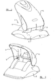
- a hole punch 1 in accordance with the invention is generally of traditional design, having a base plate 2 provided with dies defining apertures 3, and a pivotally mounted actuating handle 4 that can drive plungers 5 through the dies to punch paper introduced to the space that initially exists between the plungers and the dies.
- the handle 1 is provided with a catch element 6 which, as will become clear from the following description, may move, relative to the handle 4, between a release position, in which the punch may operate in the normal way, and a latching position, in which the handle will be retained in a depressed or lowered position.
- a catch element 6 which, as will become clear from the following description, may move, relative to the handle 4, between a release position, in which the punch may operate in the normal way, and a latching position, in which the handle will be retained in a depressed or lowered position.
- the catch element 6 is shown in the release position.
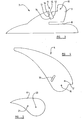
- Figure 3 shows a support plate 7 provided within the punch.
- the support plate defines a generally horizontal slit 8 which can receive an edge part of sheets of paper to be punched.
- a lug 9 Located above the horizontal slit 8 is a lug 9 defining a pivot axis 10.
- the handle 4 ( as will be described below) is mounted on the support plate to pivot about the pivot axis 10.
- the slot has, on the side closest to the pivot axis 10, an arcuate wall 12, the centre of curvature being substantially coincident with the pivot axis 10.
- the opposed wall 13 is a cranked wall, and is configured so that the lower part 14 of the slot is of greater width than the upper part 15 of the slot.
- the side wall 13 defines a region 16 which is an abutment region, and which lies on a line which intersects the pivot axis 10, or which is inclined to such a line by only a few degrees.
- the handle 4 as shown in Figure 4, is elongate and has a pivot point 17 by means of which it will be mounted for rotation relative to the support plate 7 about the axis 10. At a point spaced from the pivot point 17 there is a mounting point 18 where the latch 6 will be mounted to the handle 4.
- the handle 4 also defines an arcuate passage 19 which is spaced from the mounting point 18, but which has a centre of curvature which is substantially coincident with the mounting point 18.
- the latch 6, in the described embodiment, is of 'tear' shape and defines an axis 20 to be connected to the mounting point 18 so that the latch may pivot relative to the handle 4.
- the axis 20 is parallel with, but spaced from, the axis 10.
- the latch 6 also carries a pin 21 projecting therefom at a point spaced from the axis 20.
- the pin as will be described, is of asuch a length that when the latch is mounted to the handle 4 and the handle 4 is mounted to the support plate 7, the pin may pass through the arcuate passage 19 in the handle 4 and into the abutment slot 11 formed in the support plate 7.
- Figure 6 shows the complete assembly of the handle 4 and catch 6 when mounted on the support plate7.
- the handle 4 can pivot relative to the support plate 7 about the axis 10, and such a pivoting movement will actuate the plungers.
- the latch 6 will move together with the handle 4.
- the pin 21 is at the upper end of the arcuate passage 19. As the handle 4 and latch 6 move together the pin 21 will follow an arcuate path and will enter the upper part 15 of the abutment slot 11.
- the punch 1 will then have the condition shown in Figure 7. If the handle 4 is then release a spring biassing mechanism (not shown, but of conventional design) will return the punch to the initial condition of Figure 6.
- the catch 6 is rotated about axis 20 relative to the handle 4 while the handle is pressed down, as shown in Figure 7.
- This rotation of the catch 6 moves the catch to a locking position and moves the pin 21 to the lower end of the arcuate passage 19.
- the configuration of the lower part 14 of the abutment slot 11 permits this movement.
- the pin 21 now lies adjacent the lower part of the cranked side wall 13. This is the condition shown in Figure 8.
- the handle will move upwardly under the applied spring bias, but the pin 21 will then engage the abutment surface 16 defined by the cranked sidewall 13 of the abutment slot 11, thus preventing the handle 4 from moving further in an upward direction.
- the handle 4 is thus locked in a depressed position, which may facilitate transport and storage of the punch.
Landscapes
- Life Sciences & Earth Sciences (AREA)
- Forests & Forestry (AREA)
- Engineering & Computer Science (AREA)
- Mechanical Engineering (AREA)
- Perforating, Stamping-Out Or Severing By Means Other Than Cutting (AREA)
Applications Claiming Priority (2)
| Application Number | Priority Date | Filing Date | Title |
|---|---|---|---|
| GB0202392A GB2384739B (en) | 2002-02-01 | 2002-02-01 | Improvements in or relating to a hole punch |
| GB0202392 | 2002-02-01 |
Publications (2)
| Publication Number | Publication Date |
|---|---|
| EP1336458A2 true EP1336458A2 (de) | 2003-08-20 |
| EP1336458A3 EP1336458A3 (de) | 2004-11-10 |
Family
ID=9930246
Family Applications (1)
| Application Number | Title | Priority Date | Filing Date |
|---|---|---|---|
| EP03001960A Withdrawn EP1336458A3 (de) | 2002-02-01 | 2003-01-30 | Locher mit einem Verriegelungselement |
Country Status (2)
| Country | Link |
|---|---|
| EP (1) | EP1336458A3 (de) |
| GB (1) | GB2384739B (de) |
Cited By (5)
| Publication number | Priority date | Publication date | Assignee | Title |
|---|---|---|---|---|
| USD564594S1 (en) | 2007-03-30 | 2008-03-18 | Staples The Office Superstore, Llc | Hole punch |
| USD564593S1 (en) | 2007-03-30 | 2008-03-18 | Staples The Office Superstore, Llc | Hole punch |
| US7500813B2 (en) | 2004-05-21 | 2009-03-10 | Esselte Business Bvba | Punching and binding system and elements thereof |
| US7610838B2 (en) | 2007-03-30 | 2009-11-03 | Staples The Office Superstore, Llc | Hole punch |
| CN102202842A (zh) * | 2008-11-04 | 2011-09-28 | 斯特普尔斯办公用品超市有限公司 | 打孔器 |
Family Cites Families (5)
| Publication number | Priority date | Publication date | Assignee | Title |
|---|---|---|---|---|
| DE683624C (de) * | 1937-04-15 | 1939-11-10 | Vogel A G M | Papierlocher |
| US3714857A (en) * | 1970-09-09 | 1973-02-06 | Swingline Inc | Punch |
| DE2110356A1 (de) * | 1971-03-04 | 1972-09-14 | Rudolf Seebauer | Locher zum Lochen von Papier,wie Schriftstuecken od.dgl. |
| DE4021645A1 (de) * | 1989-08-14 | 1991-02-21 | Leitz Fa Louis | Brieflocher |
| DE29721723U1 (de) * | 1997-12-09 | 1998-03-12 | Erwin Müller GmbH & Co, 49808 Lingen | Papierlocher mit Zusatzteil zum Verriegeln des Locherhebels im heruntergedrückten Zustand |
-
2002
- 2002-02-01 GB GB0202392A patent/GB2384739B/en not_active Expired - Fee Related
-
2003
- 2003-01-30 EP EP03001960A patent/EP1336458A3/de not_active Withdrawn
Cited By (10)
| Publication number | Priority date | Publication date | Assignee | Title |
|---|---|---|---|---|
| US7500813B2 (en) | 2004-05-21 | 2009-03-10 | Esselte Business Bvba | Punching and binding system and elements thereof |
| US7503740B2 (en) | 2004-05-21 | 2009-03-17 | Esselte | Punching and binding system and elements thereof |
| US7628103B2 (en) | 2004-05-21 | 2009-12-08 | Esselte | Punching and binding systems and elements thereof |
| US7665943B2 (en) | 2004-05-21 | 2010-02-23 | Esselte Business Bvba | Punching and binding system and elements thereof |
| US7748941B2 (en) | 2004-05-21 | 2010-07-06 | Esselte Business Bvba | Punching and binding system and elements thereof |
| USD564594S1 (en) | 2007-03-30 | 2008-03-18 | Staples The Office Superstore, Llc | Hole punch |
| USD564593S1 (en) | 2007-03-30 | 2008-03-18 | Staples The Office Superstore, Llc | Hole punch |
| US7610838B2 (en) | 2007-03-30 | 2009-11-03 | Staples The Office Superstore, Llc | Hole punch |
| CN102202842A (zh) * | 2008-11-04 | 2011-09-28 | 斯特普尔斯办公用品超市有限公司 | 打孔器 |
| CN102202842B (zh) * | 2008-11-04 | 2015-06-17 | 斯特普尔斯办公用品超市有限公司 | 打孔器 |
Also Published As
| Publication number | Publication date |
|---|---|
| EP1336458A3 (de) | 2004-11-10 |
| GB2384739B (en) | 2005-07-13 |
| GB2384739A (en) | 2003-08-06 |
| GB0202392D0 (en) | 2002-03-20 |
Similar Documents
| Publication | Publication Date | Title |
|---|---|---|
| JP3079419U (ja) | スライドレールの後段ラッチ機構 | |
| US6765602B2 (en) | Thermal printer having a reduced size | |
| EP1844975B1 (de) | Sitzdrehvorrichtung für ein Fahrzeug | |
| JP5164671B2 (ja) | 車両のシートスライド装置 | |
| JP2003146126A (ja) | 車両用シートロック装置 | |
| GB2384739A (en) | Improvements in or relating to a hole punch | |
| AU2004280030B2 (en) | Striker | |
| WO2007021182A2 (en) | Lock case with divided follower | |
| JP4218121B2 (ja) | 遊技機 | |
| US5845767A (en) | Stopper structure for a switch | |
| JP3914139B2 (ja) | ドアラッチ装置 | |
| JPH0755479B2 (ja) | 書類穿孔器 | |
| JP3908506B2 (ja) | 車両用シートロック装置 | |
| JP4306992B2 (ja) | 遊技機の施錠装置 | |
| JP4149739B2 (ja) | リクライニング装置のラチェット及びその製造方法 | |
| JP3528121B2 (ja) | パチンコ機用施錠装置 | |
| JPH10264099A (ja) | 帯状刃用切欠形成打抜き装置 | |
| JP2002264703A (ja) | 自動車用シートのスライドロック機構 | |
| JPH11245681A (ja) | シフトレバー装置のディテント構造 | |
| JP3204622B2 (ja) | 自動変速機用シフトレバー装置 | |
| JP3516052B2 (ja) | 遊技機の施錠装置 | |
| JPH0641273Y2 (ja) | 電子楽器の鍵盤装置 | |
| JP3383277B2 (ja) | パチンコ機の錠装置 | |
| JP3525927B2 (ja) | 遊技機の施錠装置 | |
| JPH06168374A (ja) | 自動販売機の扉ロック機構 |
Legal Events
| Date | Code | Title | Description |
|---|---|---|---|
| PUAI | Public reference made under article 153(3) epc to a published international application that has entered the european phase |
Free format text: ORIGINAL CODE: 0009012 |
|
| AK | Designated contracting states |
Designated state(s): AT BE BG CH CY CZ DE DK EE ES FI FR GB GR HU IE IT LI LU MC NL PT SE SI SK TR |
|
| AX | Request for extension of the european patent |
Extension state: AL LT LV MK RO |
|
| PUAL | Search report despatched |
Free format text: ORIGINAL CODE: 0009013 |
|
| AK | Designated contracting states |
Kind code of ref document: A3 Designated state(s): AT BE BG CH CY CZ DE DK EE ES FI FR GB GR HU IE IT LI LU MC NL PT SE SI SK TR |
|
| AX | Request for extension of the european patent |
Extension state: AL LT LV MK RO |
|
| AKX | Designation fees paid | ||
| REG | Reference to a national code |
Ref country code: DE Ref legal event code: 8566 |
|
| STAA | Information on the status of an ep patent application or granted ep patent |
Free format text: STATUS: THE APPLICATION IS DEEMED TO BE WITHDRAWN |
|
| 18D | Application deemed to be withdrawn |
Effective date: 20050511 |