EP1336662A2 - Puce à ADN, appareil d'analyse d'échantillon et méthode correspondante - Google Patents
Puce à ADN, appareil d'analyse d'échantillon et méthode correspondante Download PDFInfo
- Publication number
- EP1336662A2 EP1336662A2 EP03250911A EP03250911A EP1336662A2 EP 1336662 A2 EP1336662 A2 EP 1336662A2 EP 03250911 A EP03250911 A EP 03250911A EP 03250911 A EP03250911 A EP 03250911A EP 1336662 A2 EP1336662 A2 EP 1336662A2
- Authority
- EP
- European Patent Office
- Prior art keywords
- spot
- image data
- reference pattern
- alignment
- processing
- Prior art date
- Legal status (The legal status is an assumption and is not a legal conclusion. Google has not performed a legal analysis and makes no representation as to the accuracy of the status listed.)
- Withdrawn
Links
Images












Classifications
-
- B—PERFORMING OPERATIONS; TRANSPORTING
- B82—NANOTECHNOLOGY
- B82Y—SPECIFIC USES OR APPLICATIONS OF NANOSTRUCTURES; MEASUREMENT OR ANALYSIS OF NANOSTRUCTURES; MANUFACTURE OR TREATMENT OF NANOSTRUCTURES
- B82Y30/00—Nanotechnology for materials or surface science, e.g. nanocomposites
-
- B—PERFORMING OPERATIONS; TRANSPORTING
- B01—PHYSICAL OR CHEMICAL PROCESSES OR APPARATUS IN GENERAL
- B01J—CHEMICAL OR PHYSICAL PROCESSES, e.g. CATALYSIS OR COLLOID CHEMISTRY; THEIR RELEVANT APPARATUS
- B01J19/00—Chemical, physical or physico-chemical processes in general; Their relevant apparatus
- B01J19/0046—Sequential or parallel reactions, e.g. for the synthesis of polypeptides or polynucleotides; Apparatus and devices for combinatorial chemistry or for making molecular arrays
-
- B—PERFORMING OPERATIONS; TRANSPORTING
- B01—PHYSICAL OR CHEMICAL PROCESSES OR APPARATUS IN GENERAL
- B01J—CHEMICAL OR PHYSICAL PROCESSES, e.g. CATALYSIS OR COLLOID CHEMISTRY; THEIR RELEVANT APPARATUS
- B01J2219/00—Chemical, physical or physico-chemical processes in general; Their relevant apparatus
- B01J2219/00274—Sequential or parallel reactions; Apparatus and devices for combinatorial chemistry or for making arrays; Chemical library technology
- B01J2219/00277—Apparatus
- B01J2219/00497—Features relating to the solid phase supports
- B01J2219/00527—Sheets
- B01J2219/00529—DNA chips
-
- B—PERFORMING OPERATIONS; TRANSPORTING
- B01—PHYSICAL OR CHEMICAL PROCESSES OR APPARATUS IN GENERAL
- B01J—CHEMICAL OR PHYSICAL PROCESSES, e.g. CATALYSIS OR COLLOID CHEMISTRY; THEIR RELEVANT APPARATUS
- B01J2219/00—Chemical, physical or physico-chemical processes in general; Their relevant apparatus
- B01J2219/00274—Sequential or parallel reactions; Apparatus and devices for combinatorial chemistry or for making arrays; Chemical library technology
- B01J2219/00277—Apparatus
- B01J2219/0054—Means for coding or tagging the apparatus or the reagents
-
- B—PERFORMING OPERATIONS; TRANSPORTING
- B01—PHYSICAL OR CHEMICAL PROCESSES OR APPARATUS IN GENERAL
- B01J—CHEMICAL OR PHYSICAL PROCESSES, e.g. CATALYSIS OR COLLOID CHEMISTRY; THEIR RELEVANT APPARATUS
- B01J2219/00—Chemical, physical or physico-chemical processes in general; Their relevant apparatus
- B01J2219/00274—Sequential or parallel reactions; Apparatus and devices for combinatorial chemistry or for making arrays; Chemical library technology
- B01J2219/00277—Apparatus
- B01J2219/0054—Means for coding or tagging the apparatus or the reagents
- B01J2219/00572—Chemical means
- B01J2219/00576—Chemical means fluorophore
-
- B—PERFORMING OPERATIONS; TRANSPORTING
- B01—PHYSICAL OR CHEMICAL PROCESSES OR APPARATUS IN GENERAL
- B01J—CHEMICAL OR PHYSICAL PROCESSES, e.g. CATALYSIS OR COLLOID CHEMISTRY; THEIR RELEVANT APPARATUS
- B01J2219/00—Chemical, physical or physico-chemical processes in general; Their relevant apparatus
- B01J2219/00274—Sequential or parallel reactions; Apparatus and devices for combinatorial chemistry or for making arrays; Chemical library technology
- B01J2219/00583—Features relative to the processes being carried out
- B01J2219/00603—Making arrays on substantially continuous surfaces
- B01J2219/00677—Ex-situ synthesis followed by deposition on the substrate
-
- B—PERFORMING OPERATIONS; TRANSPORTING
- B01—PHYSICAL OR CHEMICAL PROCESSES OR APPARATUS IN GENERAL
- B01J—CHEMICAL OR PHYSICAL PROCESSES, e.g. CATALYSIS OR COLLOID CHEMISTRY; THEIR RELEVANT APPARATUS
- B01J2219/00—Chemical, physical or physico-chemical processes in general; Their relevant apparatus
- B01J2219/00274—Sequential or parallel reactions; Apparatus and devices for combinatorial chemistry or for making arrays; Chemical library technology
- B01J2219/0068—Means for controlling the apparatus of the process
- B01J2219/00686—Automatic
- B01J2219/00689—Automatic using computers
-
- B—PERFORMING OPERATIONS; TRANSPORTING
- B01—PHYSICAL OR CHEMICAL PROCESSES OR APPARATUS IN GENERAL
- B01J—CHEMICAL OR PHYSICAL PROCESSES, e.g. CATALYSIS OR COLLOID CHEMISTRY; THEIR RELEVANT APPARATUS
- B01J2219/00—Chemical, physical or physico-chemical processes in general; Their relevant apparatus
- B01J2219/00274—Sequential or parallel reactions; Apparatus and devices for combinatorial chemistry or for making arrays; Chemical library technology
- B01J2219/0068—Means for controlling the apparatus of the process
- B01J2219/00693—Means for quality control
-
- B—PERFORMING OPERATIONS; TRANSPORTING
- B01—PHYSICAL OR CHEMICAL PROCESSES OR APPARATUS IN GENERAL
- B01J—CHEMICAL OR PHYSICAL PROCESSES, e.g. CATALYSIS OR COLLOID CHEMISTRY; THEIR RELEVANT APPARATUS
- B01J2219/00—Chemical, physical or physico-chemical processes in general; Their relevant apparatus
- B01J2219/00274—Sequential or parallel reactions; Apparatus and devices for combinatorial chemistry or for making arrays; Chemical library technology
- B01J2219/0068—Means for controlling the apparatus of the process
- B01J2219/00695—Synthesis control routines, e.g. using computer programs
-
- B—PERFORMING OPERATIONS; TRANSPORTING
- B01—PHYSICAL OR CHEMICAL PROCESSES OR APPARATUS IN GENERAL
- B01J—CHEMICAL OR PHYSICAL PROCESSES, e.g. CATALYSIS OR COLLOID CHEMISTRY; THEIR RELEVANT APPARATUS
- B01J2219/00—Chemical, physical or physico-chemical processes in general; Their relevant apparatus
- B01J2219/00274—Sequential or parallel reactions; Apparatus and devices for combinatorial chemistry or for making arrays; Chemical library technology
- B01J2219/0068—Means for controlling the apparatus of the process
- B01J2219/00702—Processes involving means for analysing and characterising the products
-
- B—PERFORMING OPERATIONS; TRANSPORTING
- B01—PHYSICAL OR CHEMICAL PROCESSES OR APPARATUS IN GENERAL
- B01J—CHEMICAL OR PHYSICAL PROCESSES, e.g. CATALYSIS OR COLLOID CHEMISTRY; THEIR RELEVANT APPARATUS
- B01J2219/00—Chemical, physical or physico-chemical processes in general; Their relevant apparatus
- B01J2219/00274—Sequential or parallel reactions; Apparatus and devices for combinatorial chemistry or for making arrays; Chemical library technology
- B01J2219/00718—Type of compounds synthesised
- B01J2219/0072—Organic compounds
- B01J2219/00722—Nucleotides
-
- C—CHEMISTRY; METALLURGY
- C40—COMBINATORIAL TECHNOLOGY
- C40B—COMBINATORIAL CHEMISTRY; LIBRARIES, e.g. CHEMICAL LIBRARIES
- C40B40/00—Libraries per se, e.g. arrays, mixtures
- C40B40/04—Libraries containing only organic compounds
- C40B40/06—Libraries containing nucleotides or polynucleotides, or derivatives thereof
-
- G—PHYSICS
- G01—MEASURING; TESTING
- G01N—INVESTIGATING OR ANALYSING MATERIALS BY DETERMINING THEIR CHEMICAL OR PHYSICAL PROPERTIES
- G01N35/00—Automatic analysis not limited to methods or materials provided for in any single one of groups G01N1/00 - G01N33/00; Handling materials therefor
- G01N35/00029—Automatic analysis not limited to methods or materials provided for in any single one of groups G01N1/00 - G01N33/00; Handling materials therefor provided with flat sample substrates, e.g. slides
- G01N2035/00099—Characterised by type of test elements
- G01N2035/00158—Elements containing microarrays, i.e. "biochip"
-
- G—PHYSICS
- G01—MEASURING; TESTING
- G01N—INVESTIGATING OR ANALYSING MATERIALS BY DETERMINING THEIR CHEMICAL OR PHYSICAL PROPERTIES
- G01N35/00—Automatic analysis not limited to methods or materials provided for in any single one of groups G01N1/00 - G01N33/00; Handling materials therefor
- G01N35/02—Automatic analysis not limited to methods or materials provided for in any single one of groups G01N1/00 - G01N33/00; Handling materials therefor using a plurality of sample containers moved by a conveyor system past one or more treatment or analysis stations
- G01N35/04—Details of the conveyor system
- G01N2035/0474—Details of actuating means for conveyors or pipettes
- G01N2035/0491—Position sensing, encoding; closed-loop control
- G01N2035/0494—Detecting or compensating piositioning errors
Definitions
- the present invention relates to a method for analyzing a DNA microarray and a sample using the DNA microarray. More specifically, it relates to technology for improving accuracy and automating image analysis of the DNA microarrays by performing the alignment of a detection area defined by an analyzing tool and image correction relative to images of the DNA microarrays read via a scanner, in the image analysis of the DNA microarrays after hybridization.
- DNA microarrays or DNA chips refer to the spotting of DNA in a grid-like pattern upon an array substrate comprising glass or the like. Upon the DNA microarrays, DNA is spotted as probes capable of specifically reacting to marked DNA samples.
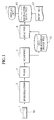
- FIG. 1 illustrates a sequence of processing in such DNA microarray analysis.
- the amount of light emission of each spotted DNA is measured by directing a laser beam with a prescribed wavelength suitable for exciting the luminescent marks (for example, Cy3, or Cy5) and by scanning the rinsed DNA microarrays within a scanner unit. Images of the scanned DNA microarrays 1 are stored in the DNA microarray image file 11.
- the DNA microarray image file 11 is read in, and analysis processing of the DNA microarrays is implemented. More specifically, in the analysis step 9, based on the image data that has been read in, the fluorescent intensity of each spot is calculated and various analyses are implemented.
- DNA microarray images which are read in through the scanner not from the DNA microarray image file 11, may be entered sequentially in the analysis step 9.
- the analysis results are recorded as digital data files 13, and may be output in a displayed format through a display unit 15 or output in a printed format through a printing unit 17 as necessary.
- FIG. 2 illustrates an example of the DNA microarrays 1 used in DNA microarray analysis.
- the DNA microarray 1 comprises blocks in which individual genes (hereafter, referred to as "spots") of complementary DNA (cDNA) are respectively arranged upon the grids of the substrate 2 in a matrix with a predetermined number thereof in each row and each column.
- spots arranged in a spot region 1a on the substrate 2 respectively correspond to DNA, each differing from each other, and having the base sequence thereof already decoded, wherein the arrangement positioning upon the substrate 2 is predetermined.
- FIG. 3 illustrates an example of a template, which is applied to the DNA microarray image file 11 during analysis processing.
- the template is divided into a plurality of fields, such as A through F, and there are a plurality of blocks (p ⁇ 24 in FIG. 3), which are formed by detection areas (corresponding to each spot of the DNA microarray) arranged in a matrix of m-row by n-column (4 x 4 in FIG. 3), within each field.
- Address numbers such as a through p and 1 through 24, are attached to the blocks in both the X and Y directions, and the position of each block can be represented, for example, as "a, 1" in each field.
- the individual spots in the read DNA microarray scanned image are applied to the detection area of the template provided by the analysis tool.
- the positioning operation by applying the detection area to the image is referred to as the alignment.
- the alignment (positioning) process must be performed correctly in order to correctly set the individual detection areas arranged upon the substrate 2 of the DNA microarrays, which is pre-defined for individual spots on the image, so that the analysis tool may calculate the fluorescent intensity of each spot on the DNA microarrays and perform the correct analysis.
- the conventional method for analyzing the DNA microarrays through the hybridization step 3 has the following problems that need to be solved.
- these problems include the low machined precision of the substrate 2, which is formed from glass and which configures the DNA microarray, and development of chips/cracks and breakage therein; the misalignment that developments when putting the DNA microarrays on the scanner autoloader or when loading them into the scanner; the accidental error built into the mechanical precision of the autoloader, the scanner, and the like; and further, the micro-dust that attaches to the substrate 2 and inevitably leads to misalignment occurring in the image file of the DNA microarrays to be analyzed.
- multiple DNA microarrays are set onto the autoloader, and the DNA microarrays are continuously scanned by the scanner to automate the accumulation of image data 11.
- DNA microarray image file detection area alignment processing and detection area alignment success/failure determination is dependent on human observation and judgment, and the inability to automate this has created a bottleneck in the processing.
- the present invention was conceived in order to solve the foregoing technical problems, one of its objects being to provide a DNA microarray, sample analysis apparatus and sample analysis method to carry out the alignment of a detection area with a DNA microarray image file quantitatively and automatically with high accuracy in the DNA microarray analysis.
- Another object of the present invention is to provide a DNA microarray, sample analysis apparatus and sample analysis method to carry out the success/ failure alignment determination processing quantitatively and automatically with high accuracy.
- Another object of the present invention is to enable parallel analysis processing and labor savings and expedited analysis processing by enabling unattended consecutive execution of steps until the desired analysis data is obtained via the scanning step through analysis step.
- a reference pattern which is utilized for the alignment of a detection area with a DNA microarray image file, is provided on the surface of a substrate of a DNA micro array to be analyzed, and the alignment processing and alignment correction processing in high accuracy are carried out by utilizing the reference pattern of the DNA microarray.
- This reference pattern may comprise a combination of spots that always emit light and spots that never emit light.
- the alignment processing is performed in a plurality of phases: by DNA microarray, by spot, and by block.
- a probe reactive chip comprising: a substrate; a spot region in which spots for fixing a probe capable of specifically reacting to a sample, which is marked so as to be optically detectable, are formed in a matrix on a surface of the substrate; and a reference pattern area, which is arranged within the spot region or approximate to the spot region, comprising a plurality of different alignment marks in order to correct a misalignment of the spots during analysis of the sample on the surface of the substrate.
- the reference pattern area may comprise a combination of spots that always emit light and spots that never emit light.
- the spot region may comprise a plurality of blocked spot sub-regions on the surface of the substrate; and the reference pattern areas are arranged within the spot sub-regions, respectively.
- the spot region may comprise a plurality of blocked spot sub-regions on the surface of the substrate; and the reference pattern areas are arranged within the spot sub-regions, respectively.
- the spot that always emits light within the reference pattern area may be a fluorescent material emitting light at a predetermined fluorescent intensity or greater.
- the spot that always emits light within the reference pattern area may be a nucleic-acid binding material.
- the spot that always emits light within said reference pattern area may be one or more of a housekeeping gene, fragments of the housekeeping gene, or a nucleic acid including the housekeeping gene or the fragment in a base sequence thereof.
- the reference pattern area may comprise a plurality of spots that never emit light being arranged surrounding a spot that always emits light.
- the probe reactive chip may further comprise a reference mark, which is for correcting misalignment of the spot region and which is arranged outside of the spot area on a surface of the substrate.
- the reference mark may be a fluorescent material emitting light at a predetermined fluorescent intensity or greater.
- the reference mark may be a nucleic-acid binding material.
- the reference mark may be one or more of a housekeeping gene, fragments of the housekeeping gene, or a nucleic acid including the housekeeping gene or the fragment in a base sequence thereof.
- the reference mark may comprise a plurality of spots that always emit light, or a combined array of spots that always emits light and spots that never emit light.
- the reference mark may indicate chip inherent information including chip type and a manufactured lot identifier.
- the spot sub-regions may be arranged having the interval with another adjacent spot sub-region be at least double the length of each spot interval within a spot region arranged within said spot sub-regions.
- a sample analysis apparatus comprising: a reference pattern information memory unit, which defines information for a reference pattern that is formed on a probe reactive chip and that comprises a plurality of different position marks for correcting a spot misalignment; an image data read in unit, which reads in image data acquired by scanning a spot for fixing a probe capable of specifically reacting to a sample upon the probe reactive chip that is marked so as to be optically detectable; an image data alignment unit, which aligns the image data with a predefined detection target area based on reference pattern area information read from the reference pattern area information memory unit, and generates correction data for correcting misalignment of the image data and the detection target area; a determination unit, which determines success/ failure of said alignment by analyzing image data aligned with the image data alignment unit; a correction unit, which correct misalignment of the image data and the detection target area based on the correction data; and an analysis unit, which analyzes the corrected image data, and outputs digitalized data relating to the sample.
- a reference pattern information memory unit
- the reference pattern area information stored in the reference pattern information memory unit may be a pattern comprising a combination spots that always emit light and spots that never emit light.
- the reference pattern area information stored in the reference pattern information memory unit may be a relative coordinate from a reference mark.
- the reference pattern area information stored in the reference pattern information memory unit may be a relative coordinate between the reference patterns.
- the reference pattern area information may be defined for each of a plurality of blocked spot sub-regions on the probe reactive chip in the reference pattern memory unit; and the image data alignment unit aligns the image data by the spot sub region.
- the analysis unit selectively operates in either automatic mode or manual mode; and the determination unit repeatedly performs analysis of the aligned image data a predetermined number of times, and adds information indicating that alignment processing for the chip has failed to output data in the case where a desired analysis result cannot be obtained.
- the sample analysis apparatus may further comprise a scanning unit, which acquires said image data by scanning a spot for fixing a probe capable of specifically reacting to a sample upon the probe reactive chip that is marked so as to be optically detectable; wherein the scanning unit and the analysis unit execute processes in parallel.
- a scanning unit which acquires said image data by scanning a spot for fixing a probe capable of specifically reacting to a sample upon the probe reactive chip that is marked so as to be optically detectable; wherein the scanning unit and the analysis unit execute processes in parallel.
- the image data alignment section comprises: a first alignment unit, which aligns a spot of the image data with a detection area by each spot in the image data; and a second alignment unit, which aligns the image data by a plurality of blocked spot sub-regions on the probe reactive chip.
- the sample analysis apparatus may further comprise a third alignment unit, which aligns the image data by the entire spot area using a reference mark.
- Another aspect of the present invention is a sample analysis method comprising: defining reference pattern area information comprising a plurality of different position marks formed on a probe reactive chip for correcting misalignment of a spot in a reference pattern information memory unit; reading in image data acquired by scanning a spot for fixing a probe capable of specifically reacting to a sample upon the probe reactive chip and marked so as to be optically detectable; aligning the image data to a predefined detection target area based on reference pattern area information read from the reference pattern area information memory unit and generating correction data for correcting misalignment of the image data and the detection target area; determining whether success/ failure of the alignment by analyzing the aligned image data; correcting a misalignment of the image data and the detection target area based on the correction data; and analyzing the corrected image data and outputting digitalized data relating to the sample.
- the reference pattern area information stored in the reference pattern information memory unit may be a pattern comprising a combination of spots that always emit light and spot that never emit light.
- the reference pattern area information stored in the reference pattern information memory unit may be a relative coordinate from a reference mark.
- the reference pattern area information stored in the reference pattern information memory unit may be a relative coordinate between said reference patterns.
- the reference pattern area information may be defined for each of a plurality of blocked spot sub-regions on the probe reactive chip in the reference pattern information memory unit; and the aligning of image data aligns the image data by the spot sub-regions.
- the analyzing may function in either automatic mode or manual mode, selectively; and the determining may repeatedly perform analysis of the aligned image data a predetermined number of times, and may add to output data information indicating that alignment processing for the chip has failed in the case where the desired analysis result cannot be obtained.
- the sample analysis method may further comprise a scanning step for acquiring the image data by scanning a spot for fixing a probe capable of specifically reacting to a sample upon the probe reactive chip and marked so as to be optically detected; wherein the scanning and the analyzing are performed in parallel.
- the image data aligning may comprise: a first alignment step for aligning a spot of the image data to a detection area by each spot in image data; and a second alignment step for aligning the image data by a plurality of blocked spot sub-regions on the probe reactive chip.
- the sample analysis method may further comprise: a third alignment step for aligning the image data by the entire spot region using a reference mark.
- Another aspect of the present invention is a program for causing a computer execute a sample analysis process, comprising: processing for defining in a reference pattern information memory unit information for a reference pattern area that is formed on a probe reactive chip and comprises a plurality of different position marks for correcting a spot misalignment; processing for reading in image data acquired by scanning a spot for fixing a probe upon the probe reactive chip and capable of specifically reacting to a sample marked so as to be optically detectable; processing for aligning the image data to a predefined detection target area based on reference pattern area information read from the reference pattern information memory unit and generating correction data for correcting misalignment of the image data and the detection target area; processing for determining success/ failure of the alignment by analyzing the aligned image data; processing for correcting misalignment of the image data and the detection target area based on the correction data; and processing for analyzing the corrected image data and outputting digitalized data relating to the sample.
- the reference pattern area information stored in the reference pattern information memory unit may be a pattern comprising a combination of spots that always emit light and spots that never emit light.
- the reference pattern area information stored in the reference pattern information memory unit may be a relative coordinate from a reference mark.
- the reference pattern area information stored in the reference pattern information memory unit may be a relative coordinate between the predefined reference patterns.
- the reference pattern area information is defined for each of a plurality of blocked spot sub-regions on the probe reactive chip in the reference pattern information memory unit; and the processing for aligning image data aligns said image data by the spot sub-regions.
- the analysis processing may function in either automatic mode or manual mode, selectively; and the determination processing may repeatedly execute an analysis for the aligned image data for the predetermined number of times, and may add information indicating that alignment processing for the chip is failed in the case where the desired analysis result cannot be obtained to output data.
- the program may further include: scanning processing for acquiring the image data by scanning a spot for fixing a probe upon the probe reactive chip and capable of specifically reacting to a sample marked so as to be optically detectable; wherein the scanning processing and the analysis processing are executed in parallel.
- the image data alignment processing may comprise: a first alignment processing for aligning a spot of the image data to a detection area in units of each spot in image data; and a second alignment processing for aligning the image data in units of a plurality of blocked spot sub-regions on the probe reactive chip.
- the program may further comprise: a third alignment processing for aligning the image data in units of the entire spot areas using a reference mark.
- Another aspect of the present invention is a program for causing a computer to execute a sample analysis process, comprising: processing for defining in a reference pattern information memory unit information for a reference pattern area that is formed on a probe reactive chip and comprises a plurality of different position marks for correcting a spot misalignment; processing for reading in image data acquired by scanning a spot for fixing a probe upon the probe reactive chip and capable of specifically reacting to a sample, which is marked so as to be optically detectable; processing for aligning the image data to a predefined detection target area based on reference pattern area information read from the reference pattern area information memory unit and generating correction data for correcting misalignment of said image data and the detection target area; processing for determining success/ failure of the alignment by analyzing the aligned image data; and processing for correcting misalignment of the image data and the detection target area based on the correction data.
- DNA microarray DNA chip
- sample analysis apparatus a sample analysis apparatus
- method thereof a method thereof are described in detail, while referencing FIGS. 4 through 33.
- detection area alignment processing and misalignment correction processing are implemented on a DNA microarray image file, providing a reference mark, which is used for detection area alignment of a DNA microarray image file, is provided upon the DNA microarray substrate to be analyzed, and in addition, a reference pattern, which is utilized for the alignment processing mentioned above as well as misalignment correction processing, is deployed within a block comprising the spot area of the DNA microarrays.
- the alignment processing is performed in a plurality of phases: by DNA microarray, by spot, and by block.
- FIG. 4 is a block diagram illustrating the overall configuration of a sample analysis system according to an embodiment of the present invention.
- the sample analysis system comprises a scanner unit 71, a control computer 73, and an analysis computer 91.
- the scanner unit 71 which comprises an autoloader mechanism for loading a plurality of DNA microarrays 1, uses a laser to excite the DNA microarrays on which the DNA samples marked with a fluorescent marker are dropped and stores the obtained image in a DNA microarray image file 11.
- the DNA microarrays 1 are scanned at excitation wavelengths corresponding to, for example, fluorescent dyes Cy3 and Cy5, respectively, obtaining for each one of the DNA microarrays 1 an image file corresponding to each respective excitation wavelength.
- the image file may be, for example, a 16-bit grey-scale Tiff format image; however, it is also allowable for it to be another Multi-Image Tiff format image or a JPEG format image.
- the control computer 73 may be, for example, a personal computer capable of connecting to the scanner unit 71 via a LAN cable, such as a general-purpose personal computer, and controls scanning as well as image acquisition of the DNA microarrays 1 by the scanner unit 71.
- the analysis computer 91 reads in the DNA microarray image file 11. Alternatively, the DNA microarray image that is read in directly from the scanner unit 71 or the control computer 73 may be entered. A group of analysis definition files 93, which define the parameters for implementing analysis, is then additionally read in, analysis of the DNA microarray image is performed, and digitalized analysis result data is output to a digitalized data file 13. A program, which acts as an analysis tool for performing analysis processing according to this embodiment, is installed into the analysis computer 91. This analysis program should act as a program for executing the analysis processing according to this embodiment and may utilize or be based in part on "GenePix Pro"TM, for example, which was developed by InterMedical Co., Ltd. and runs under Microsoft Windows.
- An analysis program running on the analysis computer 91 performs automated control of the analysis of the DNA microarray image file 11, and while the details of the processing contents will be described later, in short, it reads in the DNA microarray image file 11, reads in a group of analysis definition files 93, and performs the alignment processing (alignment processing using a reference mark) so as to match a reference mark on the read DNA microarray image to a reference position on the template to be stored in the group of analysis definition files 93.
- the analysis program implements alignment processing by spot (spot-by-spot alignment processing) on the DNA microarrays based on the image data and the detection area, as well as alignment processing for image data by block (block-by-block alignment processing), each comprising a plurality of spot regions on the DNA microarray, using the reference pattern.
- spot spot-by-spot alignment processing
- block block-by-block alignment processing
- the analysis program reattempts analysis processing a predetermined number of times, then if the number of reattempts exceeds the predetermined number of times, outputs information indicating the digitalization error for that image to a log file in order to give notice that manual digitalization should be performed.
- the analysis program ends with outputting the digitalized image data information to a digitalized data file 13.
- this analysis computer 91 may be provided in plural for a scanner unit 71/control computer 73 pair, and this plurality of units perform analysis processing for a large amount of image files in parallel.
- this scanner unit 71/control computer 73 pair is not provided, the DNA microarray image file 11 may be read in through other means.
- the group of analysis definition files 93 comprises, more specifically, an analysis parameter file 931 and an analysis automation information definition file 933.
- the analysis parameter file 931 includes the following information:
- the analysis automation information definition file 933 includes the following information:
- FIG. 35 is a block diagram illustrating the functional configuration of a sample analysis apparatus according to this embodiment.
- the sample analysis apparatus is an analysis computer 91 into which the above mentioned analysis program is installed and which comprises: an analysis image memory unit 351; a definition file memory unit 353; a reference mark alignment processing unit 355; a spot-by-spot alignment processing unit 357; a block-by-block alignment processing unit 359; an alignment determination unit 361; an analysis control unit 363; an analysis result output unit 365; a log file 367; an analysis result file 369; and an erroneous analysis image file 371.
- the analysis image memory unit 351 stores the DNA microarray image file 11 shown in FIG. 4.
- the definition file memory unit 353 stores the group of definition files shown in FIG. 4 (the analysis parameter file 931 and analysis automation information file 933 shown in FIG. 6).
- This definition file memory unit 353 corresponds to the reference pattern information memory unit in the claims.
- the reference mark alignment processing unit 355 includes the image data read in unit mentioned in the claims.
- the reference mark alignment processing unit 355, the spot-by-spot alignment processing unit 357, and the block-by-block alignment processing unit 359 correspond to the image data alignment unit and correction unit mentioned in the claims.
- the alignment determination unit 361 corresponds to the determination unit mentioned in the claims.
- the analysis control unit 363 and the analysis result output unit 365 correspond to the analysis unit mentioned in the claims.
- analysis image memory unit 351, the definition file memory unit 353, the reference mark alignment processing unit 355, the spot-by-spot alignment processing unit 357, the block-by-block alignment processing unit 359, the analysis control unit 363, the alignment determination unit 361, and the analysis result processing unit 365 are all mounted on the analysis computer 91 shown in FIG. 4.
- the analysis computer 91 may be a single unit, or alternatively, a plurality thereof may be connected over a network and configured as an analysis computer system.
- FIG. 5 illustrates an example of a portion of the digitalized data output from the analysis computer 91.
- digitalized data is collected as fluorescent intensity data regarding the respective spots detected in, for example, the Cy3 excitation wavelength and Cy5 excitation wavelength. More specifically, digitalized data 13 includes the following information relative to each spot:
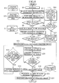
- FIG. 6 is a flowchart illustrating procedures for sample analysis processing in the sample analysis method according to an embodiment of the present invention.
- analysis program initializes and the processing is begun (step S1)
- analysis parameter file 931 and analysis automation information file 933 are read in (step S3).
- the reading in of the analysis automation information file 933 allows, for example, the name of the analysis image definition file, the name of the analysis parameter file, the number of image waiting reattempts, and the image waiting time to be read.
- the name of the analysis image definition file specifies the image and the number of pages to be analyzed to the analysis program.
- step S5 Processing from step S5 through step S35 is repeatedly executed until the number of pages of the image to be analyzed reaches the total number of pages of the image that has been read in (i.e., end conditions End are met) (step S5).
- step S7 whether or not there is an image to be analyzed is determined (step S7), and if there is no image to be analyzed (step S7N), the number of times to reattempt image waiting is read in step S3, and processing from step S11 through step S15 is repeatedly performed until the number of times set in the analysis program is exceeded.
- step S13 whether or not there is an image to be analyzed is determined (step S13), and if there is an image to be analyzed (step S13Y)
- step S9 meanwhile if there is no image to be analyzed obtained (step S13N), the counter of the number of times to reattempt image waiting is incremented (step S15), and if the set number of times is exceeded, processing proceeds to step S35.
- step S7 if there is an image to be analyzed (step S7Y), the corresponding image file is read in from the DNA microarray image file 11 as the DNA microarray to be analyzed (step S9). Otherwise, the image file to be analyzed may be entered directly from the scanner unit 71 and control computer 73 bypassing the DNA microarray image file 11. Continuing, alignment processing using the reference marks (above mentioned reference mark alignment processing) is performed (step S17). After executing alignment processing using the reference marks in step S17, image processing is performed on the image data (step S19), and if the image processing is determined to have failed (step S19N), the processing proceeds to step S35. Meanwhile, if the image processing is determined to have been a success, the post-image processing image file is read in (step S21).
- step S23 alignment processing is performed by spot on the DNA microarrays (the above-mentioned spot-by-spot alignment processing) (step S23), and in addition alignment processing by block is performed on the DNA microarrays (the above-mentioned block-by-block alignment processing) (step S25). It should be noted that it does not matter whether step S23 or step S25 is performed first, as long as they are performed after the analysis image read processing in step S21 and before the alignment determination in step S27.
- step S27 Whether alignment is successful or not successful is determined based on the image data digitalized after the reference mark alignment processing and the spot-by-spot alignment processing (step S27). If alignment is determined to be successful (step S27Y), the digitalized image data is output to the digitalized data file 13, and the counter of the number of pages of the image to be analyzed is incremented (step S35). Meanwhile, if the alignment is determined to have been a failure (step S27N), then it is determined whether the predetermined number of times of detection area shifting (or shift times) has been exceeded (step S31), and if the predetermined number of detection area shift times has been reached (step S31N), then processing proceeds to step S35.
- step S31Y if the predetermined number of detection area shift times has not yet been exceeded (step S31Y), then detection area shift processing (correction processing) by block of the DNA microarrays is performed (step S33), and the processing returns to the spot-by-spot alignment processing in step S23.
- step S33 under the assumption that alignment using reference marks is for the most part correct, alignment of a spot/detection area pair is attempted starting with small shifts and gradually becoming larger shifts as clockwise rotation progresses.
- processing from step S7 through step S35 may be repeatedly performed the predetermined number of times for the image in which the analysis error occurs (step S37).
- FIG. 7 is a flowchart describing in more detail the reference mark alignment processing in step S17 shown in FIG. 6 with the reference mark according to this embodiment.
- the reference mark analysis processing unit 355 reads in the DNA microarray image file (step S171), and automatically recognizes the template including the reference pattern recognition area, which has been read in from the analysis automation information file 933 in advance, and in addition performs analysis (digital) processing of the image file and aligns the reference marks so as to match the reference pattern of the read image file to the reference pattern definition positioned within the reference pattern recognition area on the template.
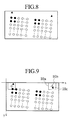
- FIG. 8 illustrates an example of the image file that is read in step S171.
- the reference marks used for the reference mark alignment processing according to this embodiment have been arranged in the periphery of the spot region where the spots have been pre-arranged on the substrate.
- This reference mark may be a mark made by a material that gives off a luminescent signal when the DNA microarrays are scanned by the scanner unit 71, for example, fluorescent materials, such as autofluorescent materials, nucleic-acid binding materials, housekeeping genes, a fragment of the housekeeping genes, or nucleic acid including the housekeeping gene or the fragment in a base sequence thereof may be used.
- fluorescent materials such as autofluorescent materials, nucleic-acid binding materials, housekeeping genes, a fragment of the housekeeping genes, or nucleic acid including the housekeeping gene or the fragment in a base sequence thereof may be used.
- the autofluorescent material is a material that naturally has fluorescence as one of its inherent physical properties.
- the autofluorescent material gives off a fluorescent signal when the DNA microarrays are scanned.
- the nucleic-acid binding material should be a material that absorbs fluorescent-marked nucleic acid within a sample to be dropped on the DNA microarrays although it may not have fluorescence as one of its inherent physical properties, for example, a polyallylamine may be used. Since the nucleic-acid binding material absorbs the fluorescent-marked nucleic acid, it gives off a fluorescent signal when the DNA microarrays are scanned.
- Housekeeping genes are genes naturally appearing within a living organism in amounts having a constant minimum, and do not have fluorescence as a physical property. Since the hybridization always occurs with the fluorescent marked nucleic acid within the sample fluid, if the housekeeping genes are spotted on the DNA microarrays, a fluorescent signal is also emitted when the DNA microarrays are scanned. When these autofluorescent materials, nucleic-acid binding materials, and housekeeping genes are all spotted on the DNA microarrays, they become spots having the characteristic of always emitting light when they are scanned, and these are referred to as positive controls in this specification. On the contrary, the spots having the characteristic of not always emitting light when they are scanned are referred to as negative controls in this specification.
- FIG. 9 illustrates a status that the template including the reference mark recognition area is automatically recognized relative to the image shown in FIG. 8, which has been read in through the scanner unit 71.
- FIG. 9 a situation where a misalignment occurs between a reference mark definition position 10b within the reference mark recognition area 10a on the template and a reference mark 10c within the image file, which has been read in, is illustrated.
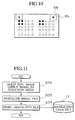
- the analysis program corrects the position from this misaligned state so as to fit the reference mark 10c within the image file to the reference mark definition position 10b on the template, as shown in FIG. 10.
- the reference mark recognition area 10a and the reference pattern definition position 10b on the template are illustrated for convenience, thus it is not necessary for it to be visibly represented as an actual image.
- the entire DNA microarrays i.e., the entire spot area on the array
- the entire template is substantially aligned relative to the entire template.
- the amount of shift according to the misalignment of the definition position 10b of the reference mark in the reference mark recognition area 10a of the template and the reference mark 10c in the image file, which is read in, shown in FIG. 9 is calculated (step S175), and the image is rotated and shifted based on the calculated amount of shift as shown in FIG. 10 (step S177).
- the corrected image file is stored in an image file 11b in which the post-correction image files are stored. It should be noted that the storage location may be an image file 11, from which the image file is read in step 171.
- step S23 in FIG. 6 a detail of the spot-by-spot alignment processing in this embodiment is described.
- FIG. 11 is a flowchart describing the details of the spot-by-spot alignment processing in step S23 shown in FIG. 6, which is performed by spot on the DNA microarrays according to this embodiment.
- the spot-by-spot alignment processing unit 357 performs alignment (step S231) for each spot image in each DNA microarray in the post-position correction processing image file 11b (image processing), which is read in step S21, to the detection area corresponding to each spot of the template, which has been read in beforehand from the analysis automation information file 933.
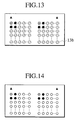
- FIG. 13 illustrates a situation where each detection area of the template is applied to the DNA microarray image after position correction, which is read in step S21 shown in FIG. 6.
- FIG. 13 the state where each detection area 13b of the template and each spot in the image file, which is read in, are misaligned is illustrated.
- the analysis program has the spot-by-spot alignment processing unit 357 perform positional correction so as to fit each spot image in the image file to each detection area on the template from this misaligned status as shown in FIG. 14.
- the image file after position correction shown in FIG. 14 is digitalized based on the definition information of the template (step S233), and the digitalized file is stored in the digitalized data file 13 (step S235).
- step S25 in FIG. 6 the alignment processing by block (step S25 in FIG. 6) in this embodiment is described in further detail.
- both alignment processing by pattern matching using the pattern array of the reference pattern and alignment processing using reference pattern position coordinates are utilized. Alternatively, only one of the two may be performed.
- FIG. 15 illustrates an example of the DNA microarray image file, which is incorrectly aligned by the spot-by-spot alignment processing in step S23 of FIG. 6.
- the spot-by-spot alignment is executed by trying to match the detection area block on the template to a spot within a block for each block on the DNA microarrays. Accordingly, for example, if there should be a dust particle attached to the substrate of the DNA microarrays, the detection area to which each spot should be matched may be incorrectly determined, and an error in aligning the block may result.
- the above mentioned alignment error due to the occurrence of micro-dust is inevitable.
- reference patterns for adjusting block-by-block alignment are arranged beforehand within a block on the DNA microarrays, and the alignment error due to spot-by-spot alignment processing is adjusted.
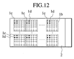
- FIG. 12 illustrates an example of the DNA microarrays used for this embodiment.
- a plurality of groups of blocks 1b is arranged upon the DNA microarrays 1.
- Genes are spotted in each block, and in this embodiment, both positive controls, which are spots that always emit light, and negative controls, which are spots that never emit light (emission is rare), are arranged in each block.
- positive controls and negative controls are normally used as markers in order to determine whether there are errors in the processing of the hybridization step.
- reference patterns comprising combinations of these positive controls and negative controls are formed.
- This reference pattern is arranged within each block in which the spots for fixing genes, or probes, are formed in a matrix, thereby it may be regarded as the block-by-block alignment reference pattern for block-by-block alignment processing.
- This block corresponds to the spot sub-region mentioned in the claims.
- positive control may be, similar to the above mentioned reference mark, a mark generated by a material, which emits a luminescent signal when the DNA microarrays are scanned by the scanner unit 71, for example, autofluorescent materials, nucleic-acid absorption materials, housekeeping genes, fragments of the housekeeping genes, or nucleic acid including the housekeeping gene or the fragment in a base sequence thereof may be used.
- the positive controls are arranged within each block as shown by 1c in FIG. 12, while the negative controls are arranged surrounding them as shown by 1d.
- the reference patterns may be provided at a corner within a block or may be provided at the arbitrary position within the block. Or, it may be provided outside of, but approximately to, the blocks comprising the spot region, if necessary.
- Information regarding the pattern array and position coordinates of positive controls and negative controls arranged within the block is registered beforehand in the analysis automation information file 933 as one of the attribute information for the template.
- spot positions within each block may be specified by executing the determination of the fluorescent intensity and position coordinates of these positive controls and negative controls.
- Another pattern comprising positive controls surrounded by negative controls may be further deployed within the reference pattern in the block; alternatively, another pattern of positive controls surrounded by negative controls may be further deployed relative to a pattern within the block upon lines diagonal to the block.
- the erroneous determination due to the occurrence of dust in the DNA microarrays may be reduced by arranging other patterns to construct a plurality of reference patterns within one block.
- the area occupied with reference patterns comprising positive controls surrounded by negative controls be small.
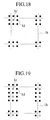
- FIGS. 18 through 23 illustrate examples of pattern arrangements of positive controls surrounded by negative controls according to this embodiment. It should be noted that in FIGS. 18 through 23, it is assumed that all genes other than the positive controls and negative controls within the block are spotted.
- the determination criteria for successful alignment in block-by-block alignment processing is that the fluorescent intensity of the positive control be a specified minimum fluorescent intensity or greater, but less than the threshold value, to which the positive control coordinates are pre-set as the attributes of the template.
- the negative controls 1d are arranged astride a block 1b around one positive control 1c, thus the necessary number of positive and negative controls is nine per block.
- this pattern is adopted, if one or more particles of dust having intensity stronger than the minimum fluorescent intensity exist on the periphery of the positive controls, they are incorrectly recognized as positive controls.
- the negative controls 1d are arranged astride the block 1b around two separated positive controls 1c, thus the necessary number of positive and negative controls is fifteen per block.
- this pattern is adopted, if two or more particles of dust having intensity stronger than the minimum fluorescent intensity exist on the periphery of the positive controls, they are incorrectly recognized as positive controls.
- the negative controls 1d are arranged astride the block 1b around one positive control 1c, and in addition, in the opposing corner of the block, the negative controls 1d are arranged surrounding one positive control 1c; thus, the necessary number of positive and negative controls is sixteen per block.
- this pattern is adopted, if two or more particles of dust having intensity stronger than the minimum fluorescent intensity exist on the periphery of the positive controls, they are incorrectly recognized as positive controls.
- the detection of rotational misalignment of the block is reinforced through comparison with the pattern of FIG. 18.
- the block 1b pitch is at least twice the length of the spot pitch (i.e., there is an interval between the blocks 1b that correlates to one spot 1e).
- the block 1b is arranged with an interval of at least one spot from the adjacent block 1b.
- the negative controls 1d are arranged around one positive control 1c, which is arranged in one of the four corners, thus the necessary number of positive and negative controls is four per block.
- this pattern is adopted, if one or more particles of dust having intensity stronger than the minimum fluorescent intensity exist on the periphery of the positive controls, they are incorrectly recognized as positive controls.
- the block 1b is arranged with an interval of at least one spot from the adjacent block 1b.
- Negative controls 1d are arranged around one positive control 1c, which is arranged in one of the four corners, and in addition, negative controls 1d are arranged in the opposing corner around one positive control 1c; thus, the necessary number of positive and negative controls is eight per block.
- this pattern is adopted, if two or more particles of dust, which have intensity stronger than the minimum fluorescent intensity, exist with the same arrangement as the two positive controls on the periphery of the positive controls, they are incorrectly recognized as positive controls.
- block 1b is arranged with an interval of at least one spot from the adjacent block 1b.
- the negative controls 1d are arranged around a positive control 1c, which is arranged at one of the four corners, and another positive control separated therefrom; thus the necessary number of positive and negative controls is eight per block.
- FIGS. 18 through 23 the negative controls are arranged surrounding the positive controls; this arrangement is used in this embodiment for the following reasons.
- FIG. 16 for example, the arrangement of a block arranged with only one positive control, a block arranged with two positive controls side by side, and a block arranged with two positive controls in opposing corners, wherein negative controls are assigned, is assumed.
- FIG. 17 illustrates conditions after executing block-by-block alignment processing on a detection area upon a template by an analysis program in relation to the arrangement shown in FIG. 16. During determination of success/ failure after block-by-block alignment processing,
- the allowable amount of position coordinate misalignment may be specified as at least twice the length of the spot intervals. Therefore, significant and accurate success/failure determination for alignment may be implemented. It should be noted that without using determinations (1) and (2) even with determination using positive control and negative control pattern matching, as long as the post-alignment pattern and the pattern on the template do not have the same pattern array, it is valid since alignment is not determined as successful.
- the configuration in which the positive controls are doubly enclosed by the negative controls as shown in FIG. 34 is desirable. If there is by chance a DNA spot array having an array with the same fluorescent intensity, and it is incorrectly recognized when applying the detection area to the image, alignment may be accurately determined as unsuccessful through position coordination determination even though the positive controls and negative controls are determined as successful.
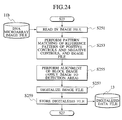
- FIG. 24 is a flowchart describing the detail of the block-by-block alignment processing in step S25 shown in FIG. 6, which is implemented block-by-block with the array pattern of the positive and negative controls on the DNA microarrays, according to this embodiment.
- the block-by-block alignment processing unit 359 reads the image file 11b, which is read in step S21, after position correction processing (image processing) (step S251). Pattern matching between the reference patterns of the positive controls and negative controls pre-defined on the template and the image file is then performed (step S253). Otherwise, in this step S253, position coordinate determination may be used in conjunction with pattern matching or in exchange thereof.
- step S255 application of the block image to the detection area is reattempted, and the block image is aligned based on the calculated amount of shift (step S255).
- step S257 the image file is digitalized (step S257), and the digitalized data is stored in the digital data file 13 (step S259).
- spot-by-spot alignment processing and block-by-block alignment processing
- digitalization (analysis) of each spot is implemented, and determinations of number, fluorescent intensity, and position coordinates of the positive controls and negative controls are performed, and it is determined whether the alignment is properly executed.
- FIG. 25 illustrates an example of post-digitalized data of each spot.
- Pn represents spots of interest (for example, positive controls).
- In represents the fluorescent intensity of Pn.
- (xn, yn) represents real coordinates of Pn upon an image.
- (Xn, Yn) represent coordinates of Pn in design.
- n is a natural number from 1 to Z.
- Determination is executed using both or either one of the following determination methods.
- the analysis result output unit 365 stores digitalized data, of which alignment has been determined as successful, in the digital data file 13. Meanwhile, as for the image that does not obtain a successful alignment determination even with the predetermined number of re-alignments (step S35 in FIG. 6), the analysis result output unit 365 outputs to a log file 367 information indicating that a successful determination is not obtained, and additionally outputs to an erroneous analysis image file 371 the image, which does not obtain the successful determination, as an erroneous image. This erroneously analyzed image is submitted for alignment processing through human observation.
- the analysis control unit 363 invokes and executes the reference mark alignment processing unit 355, the spot-by-spot alignment processing unit 357, the block-by-block alignment processing unit 359, the alignment determination unit 361, and the analysis result output unit 365; thereby a sequence of the entire analysis processing shown in FIG. 6 is implemented.
- FIG. 26 illustrates an example of a screen display during the image recognition processing of the scanned image, which is entered from the DNA microarray image file 11.
- the position coordinates of the reference mark which is arranged outside of and on either side of the spot region within the scanned image, is displayed, and based on this reference mark position coordinate, a message that the rotational shift (rotational compensation) is being implemented in the recognition processing (image processing) of the scanned image is displayed.
- a manual rotation angle calculation button 265 and a manual rotation processing button 267 are provided.
- FIG. 27 illustrates an example of an image display of the scanned image read in from the DNA microarray image file 11. Spots with respective fluorescent intensities including the positive controls and negative controls are arranged within the DNA microarray block.
- FIG. 28 illustrates an example of a situation where the detection area of the template registered in the analysis parameter file 931 is invoked for the displayed representation of the image of FIG. 27.
- Each spot image within the DNA microarray image and each detection area on the template are misaligned.
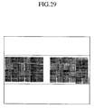
- FIG. 29 illustrates an example of the post-alignment state for the image shown in FIG. 28, in the case where this embodiment is not utilized.
- the condition wherein accurate alignment is not performed, and alignment of the detection area is erroneous is illustrated. If this embodiment is not utilized, from the state in this FIG. 29, it is necessary to repeatedly performing a compensation operation, which applies to the image the detection areas by shifting them one by one through human observation.
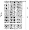
- FIG. 30 illustrates an example of the post-alignment state in the case where the reference patterns comprising combinations of positive controls and negative controls in this embodiment are not utilized.
- the reference patterns comprising combinations of positive controls and negative controls in this embodiment are not utilized.
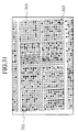
- FIG. 31 illustrates an example of the situation when misalignment has occurred in the case where the reference pattern 311, which comprises a combination of positive and negative controls, is arranged in only one corner of the block.
- the reference pattern 311 which comprises a combination of positive and negative controls
- FIG. 31 illustrates an example of the situation when misalignment has occurred in the case where the reference pattern 311, which comprises a combination of positive and negative controls, is arranged in only one corner of the block.
- the alignment is determined as successful in the reference determination and determination using position coordinates (block-by-block alignment) even if the alignment is erroneous.
- the alignment determination may be accurately performed by arranging the reference patterns comprising the positive and negative controls, for example, in an opposing corner 313.
- FIG. 32 illustrates an example of the state when the alignment determination is successful in this embodiment in the case where the reference pattern 311, which comprises a combination of positive and negative controls, is arranged in only one corner of the block.
- the reference pattern comprising positive and negative controls is arranged upon the block in one corner.
- FIG. 33 is a block diagram illustrating a hardware structure of the sample analysis apparatus and sample analysis system according to an embodiment of the present invention.
- the sample analysis apparatus for example, has a structure as shown in FIG. 33.
- the sample analysis apparatus according to an embodiment of the present invention is constructed by incorporating each element of the sample analysis processing within one or a plurality of computer systems.
- a computer system 100 comprising a central processing unit 110, such as a microprocessor, and many other units connected together through a system bus 112.
- This computer system comprises random access memory 114; read-only memory 116; an I/O adapter 118, which connects peripheral units, such as a hard disk unit 120, to the system bus 112; a user interface adapter 122, which connects user interface units, such as a keyboard 124, a mouse 126, a speaker 128, a microphone 132, or a touch screen (not shown in the figure) to the system bus 112; a communication adapter 134, which connects this computer system to a communication network; a display adapter 136, which connects a display unit 138 to the system bus 112; and an external disk driver 142, which respectively activates a floppy disk 144, an optical disk 146, and various memory cards 148.
- sample analysis program for executing each function of the sample analysis processing according to this embodiment that is stored in these storage media, by storing the analysis program for executing each function of the sample analysis processing according to this embodiment in various computer readable storage media, which are represented by these floppy disk 144, optical disk 146, and various memory cards 148, and performing a predetermined reading operation from these storage media via the external disk driver.
- the sample analysis processing according to this embodiment is implemented by loading these programs into the random access memory 114 and executing thereof with the central processing unit 110.
- the above mentioned sample analysis program may be executed either on one computer or a plurality of computers linked over a network. When the program is executed on a plurality of computers, modules running on each computer are loaded therein through the storage media in which the modules are stored.
- the following effects may be obtained. Namely, in the analysis of the DNA microarrays, alignment processing of the detection area to the DNA microarray image file, and alignment success/ failure determination processing may be executed quantitatively, through automation, and with high accuracy. Particularly, accompanying miniaturization of spot intervals on the DNA microarrays, since manual alignment processing becomes difficult, a bottleneck due to a sequence of sample analysis processing may be widely reduced according to this embodiment.
- DNA spotted on the DNA microarrays is described by means of an embodiment, but is not limited thereto.
- the DNA microarrays according to this embodiment are not limited to DNA, and may be applied to, for example, biomolecules, which combine in a unique manner such as RNA and protein.
- alignment processing of the detection area with an DNA microarray image file, and success/ failure alignment determination processing may be executed quantitatively, through automation, and with high accuracy.
Landscapes
- Chemical & Material Sciences (AREA)
- Engineering & Computer Science (AREA)
- Nanotechnology (AREA)
- Organic Chemistry (AREA)
- Composite Materials (AREA)
- General Physics & Mathematics (AREA)
- Materials Engineering (AREA)
- Crystallography & Structural Chemistry (AREA)
- Condensed Matter Physics & Semiconductors (AREA)
- Physics & Mathematics (AREA)
- Chemical Kinetics & Catalysis (AREA)
- Measuring Or Testing Involving Enzymes Or Micro-Organisms (AREA)
- Apparatus Associated With Microorganisms And Enzymes (AREA)
- Investigating, Analyzing Materials By Fluorescence Or Luminescence (AREA)
Applications Claiming Priority (4)
| Application Number | Priority Date | Filing Date | Title |
|---|---|---|---|
| JP2002037418 | 2002-02-14 | ||
| JP2002037418 | 2002-02-14 | ||
| JP2002259338 | 2002-09-04 | ||
| JP2002259338A JP3670260B2 (ja) | 2002-02-14 | 2002-09-04 | プローブ反応性チップ |
Publications (2)
| Publication Number | Publication Date |
|---|---|
| EP1336662A2 true EP1336662A2 (fr) | 2003-08-20 |
| EP1336662A3 EP1336662A3 (fr) | 2004-02-18 |
Family
ID=27624616
Family Applications (1)
| Application Number | Title | Priority Date | Filing Date |
|---|---|---|---|
| EP03250911A Withdrawn EP1336662A3 (fr) | 2002-02-14 | 2003-02-14 | Puce à ADN, appareil d'analyse d'échantillon et méthode correspondante |
Country Status (2)
| Country | Link |
|---|---|
| EP (1) | EP1336662A3 (fr) |
| JP (1) | JP3670260B2 (fr) |
Cited By (13)
| Publication number | Priority date | Publication date | Assignee | Title |
|---|---|---|---|---|
| WO2008096318A3 (fr) * | 2007-02-09 | 2008-10-30 | Koninkl Philips Electronics Nv | Système d'identification |
| EP1747524A4 (fr) * | 2004-05-07 | 2009-10-21 | Wisconsin Alumni Res Found | Système d'immobilisation d'image pour synthèse de puce à adn |
| US20210097684A1 (en) * | 2019-10-01 | 2021-04-01 | 10X Genomics, Inc. | Systems and methods for identifying morphological patterns in tissue samples |
| EP2864765B1 (fr) * | 2012-06-22 | 2021-04-28 | Roche Diabetes Care GmbH | Procédé et dispositif pour détecter un analyte dans un fluide corporel |
| WO2021102005A1 (fr) * | 2019-11-22 | 2021-05-27 | 10X Genomics, Inc. | Systèmes et procédés d'analyse spatiale d'analytes à l'aide d'un alignement de repères |
| WO2021102039A1 (fr) * | 2019-11-21 | 2021-05-27 | 10X Genomics, Inc, | Analyse spatiale d'analytes |
| CN113227342A (zh) * | 2019-01-09 | 2021-08-06 | 株式会社日立高新技术 | 核酸分析用基板、核酸分析用流动池以及图像分析方法 |
| US12112833B2 (en) | 2020-02-04 | 2024-10-08 | 10X Genomics, Inc. | Systems and methods for index hopping filtering |
| US12154266B2 (en) | 2019-11-18 | 2024-11-26 | 10X Genomics, Inc. | Systems and methods for binary tissue classification |
| US12168801B1 (en) | 2020-07-02 | 2024-12-17 | 10X Genomics, Inc. | Hybrid/capture probe designs for full-length cDNA |
| US12421558B2 (en) | 2020-02-13 | 2025-09-23 | 10X Genomics, Inc. | Systems and methods for joint interactive visualization of gene expression and DNA chromatin accessibility |
| EP4430380A4 (fr) * | 2021-11-08 | 2026-01-07 | Eb Bio Consulting Inc | Analyse automatique et parallèle d'images de microréseau |
| US12580044B1 (en) | 2020-09-02 | 2026-03-17 | 10X Genomics, Inc. | Systems and methods for identifying cells that are antigen-specific for an immunogenic feature |
Families Citing this family (19)
| Publication number | Priority date | Publication date | Assignee | Title |
|---|---|---|---|---|
| WO2007018872A1 (fr) * | 2005-07-20 | 2007-02-15 | Corning Incorporated | Système et procédé de criblage biomoléculaire de rendement élevé sans étiquetteod |
| JP4711125B2 (ja) | 2005-09-27 | 2011-06-29 | 横河電機株式会社 | バイオチップ、バイオチップ読み取り装置、およびバイオチップ読み取り方法 |
| JP5092405B2 (ja) * | 2006-01-12 | 2012-12-05 | 東レ株式会社 | 選択結合性物質固定化担体 |
| JP2008256428A (ja) * | 2007-04-03 | 2008-10-23 | Intec Systems Institute Inc | マイクロアレイ画像のブロック位置検出方法 |
| JP5205798B2 (ja) | 2007-04-27 | 2013-06-05 | 富士通株式会社 | マイクロインジェクション装置、捕捉プレート、およびマイクロインジェクション方法 |
| US8497068B2 (en) | 2009-06-16 | 2013-07-30 | Toyo Kohan Co., Ltd. | Method for detecting a position of probe on microarray |
| JP5817378B2 (ja) * | 2011-01-28 | 2015-11-18 | 東レ株式会社 | マイクロアレイの解析方法および読取り装置 |
| WO2013119845A1 (fr) | 2012-02-07 | 2013-08-15 | Vibrant Holdings, Llc | Substrats, réseaux de peptides et procédés |
| WO2014052989A2 (fr) * | 2012-09-28 | 2014-04-03 | Vibrant Holdings, Llc | Procédés, systèmes et arrangements d'analyse biomoléculaire |
| US10286376B2 (en) | 2012-11-14 | 2019-05-14 | Vibrant Holdings, Llc | Substrates, systems, and methods for array synthesis and biomolecular analysis |
| JP2014226055A (ja) * | 2013-05-20 | 2014-12-08 | 株式会社ニコン | 検出方法、検出装置、スクリーニング方法、スクリーニング装置、及びバイオチップ |
| JP2015194379A (ja) * | 2014-03-31 | 2015-11-05 | 株式会社ニコン | バイオチップ及びバイオチップにおけるアライメントマークの検出方法 |
| JP6459438B2 (ja) * | 2014-11-27 | 2019-01-30 | 東洋製罐グループホールディングス株式会社 | マイクロアレイにおけるプローブの位置決定方法、及び標識反応用キット |
| US10711294B2 (en) | 2014-12-26 | 2020-07-14 | Hitachi High-Tech Corporation | Nucleic acid analysis device |
| JPWO2017179085A1 (ja) * | 2016-04-13 | 2019-02-21 | 東洋製罐グループホールディングス株式会社 | マイクロアレイにおけるプローブの位置決定方法、及び標識反応用キット |
| EP3281701B1 (fr) * | 2016-08-10 | 2021-07-14 | Roche Diagnostics GmbH | Plaque à puits pour des réactions chimiques ou biologiques et procédé d'imagerie multiples d'une telle plaque au moyen d'un système d'imagerie |
| JP2018049034A (ja) * | 2017-12-18 | 2018-03-29 | 株式会社ニコン | 検出方法、検出装置、スクリーニング方法、スクリーニング装置、及びバイオチップ |
| JP2018124289A (ja) * | 2018-04-10 | 2018-08-09 | 株式会社ニコン | バイオチップ及びバイオチップにおけるアライメントマークの検出方法 |
| JP7091164B2 (ja) * | 2018-06-27 | 2022-06-27 | 株式会社日立ハイテク | 核酸分析用基板、核酸分析用フローセル、及び解析方法 |
Family Cites Families (6)
| Publication number | Priority date | Publication date | Assignee | Title |
|---|---|---|---|---|
| US6027880A (en) * | 1995-08-02 | 2000-02-22 | Affymetrix, Inc. | Arrays of nucleic acid probes and methods of using the same for detecting cystic fibrosis |
| EP1002297A1 (fr) * | 1997-08-07 | 2000-05-24 | Imaging Research, Inc. | Systeme d'imagerie numerique destine a des dosages dans des plaques a puits, dans des gels et des papiers filtres |
| CA2359352C (fr) * | 1999-02-09 | 2004-09-21 | Illumina, Inc. | Traitement informatise d'informations dans des groupements ordonnes de maniere aleatoire |
| US6362004B1 (en) * | 1999-11-09 | 2002-03-26 | Packard Biochip Technologies, Llc | Apparatus and method for using fiducial marks on a microarray substrate |
| WO2002072889A2 (fr) * | 2001-01-12 | 2002-09-19 | Applera Corporation | Methodes et compositions pour analyse de microreseaux |
| US7636636B2 (en) * | 2001-10-12 | 2009-12-22 | Abbott Laboratories | Imaging microarrays |
-
2002
- 2002-09-04 JP JP2002259338A patent/JP3670260B2/ja not_active Expired - Fee Related
-
2003
- 2003-02-14 EP EP03250911A patent/EP1336662A3/fr not_active Withdrawn
Cited By (26)
| Publication number | Priority date | Publication date | Assignee | Title |
|---|---|---|---|---|
| EP1747524A4 (fr) * | 2004-05-07 | 2009-10-21 | Wisconsin Alumni Res Found | Système d'immobilisation d'image pour synthèse de puce à adn |
| WO2008096318A3 (fr) * | 2007-02-09 | 2008-10-30 | Koninkl Philips Electronics Nv | Système d'identification |
| EP2864765B1 (fr) * | 2012-06-22 | 2021-04-28 | Roche Diabetes Care GmbH | Procédé et dispositif pour détecter un analyte dans un fluide corporel |
| CN113227342A (zh) * | 2019-01-09 | 2021-08-06 | 株式会社日立高新技术 | 核酸分析用基板、核酸分析用流动池以及图像分析方法 |
| US12125260B2 (en) | 2019-10-01 | 2024-10-22 | 10X Genomics, Inc. | Systems and methods for identifying morphological patterns in tissue samples |
| US11514575B2 (en) * | 2019-10-01 | 2022-11-29 | 10X Genomics, Inc. | Systems and methods for identifying morphological patterns in tissue samples |
| US20210097684A1 (en) * | 2019-10-01 | 2021-04-01 | 10X Genomics, Inc. | Systems and methods for identifying morphological patterns in tissue samples |
| US11756286B2 (en) * | 2019-10-01 | 2023-09-12 | 10X Genomics, Inc. | Systems and methods for identifying morphological patterns in tissue samplers |
| US20230081613A1 (en) * | 2019-10-01 | 2023-03-16 | 10X Genomics, Inc. | Systems and methods for identifying morphological patterns in tissue samples |
| US12154266B2 (en) | 2019-11-18 | 2024-11-26 | 10X Genomics, Inc. | Systems and methods for binary tissue classification |
| CN117078725A (zh) * | 2019-11-21 | 2023-11-17 | 10X基因组学有限公司 | 分析物的空间分析 |
| CN115210760B (zh) * | 2019-11-21 | 2023-08-01 | 10X基因组学有限公司 | 分析物的空间分析 |
| CN115210760A (zh) * | 2019-11-21 | 2022-10-18 | 10X基因组学有限公司 | 分析物的空间分析 |
| WO2021102039A1 (fr) * | 2019-11-21 | 2021-05-27 | 10X Genomics, Inc, | Analyse spatiale d'analytes |
| EP4435718A3 (fr) * | 2019-11-22 | 2024-12-18 | 10X Genomics, Inc. | Systèmes et procédés d'analyse spatiale d'analytes à l'aide d'un alignement de repères |
| CN115023734B (zh) * | 2019-11-22 | 2023-10-20 | 10X基因组学有限公司 | 使用基准对齐对分析物进行空间分析的系统和方法 |
| CN117746422A (zh) * | 2019-11-22 | 2024-03-22 | 10X基因组学有限公司 | 使用基准对齐对分析物进行空间分析的系统和方法 |
| US11501440B2 (en) | 2019-11-22 | 2022-11-15 | 10X Genomics, Inc. | Systems and methods for spatial analysis of analytes using fiducial alignment |
| CN115023734A (zh) * | 2019-11-22 | 2022-09-06 | 10X基因组学有限公司 | 使用基准对齐对分析物进行空间分析的系统和方法 |
| WO2021102005A1 (fr) * | 2019-11-22 | 2021-05-27 | 10X Genomics, Inc. | Systèmes et procédés d'analyse spatiale d'analytes à l'aide d'un alignement de repères |
| US12229974B2 (en) | 2019-11-22 | 2025-02-18 | 10X Genomics, Inc. | Systems and methods for spatial analysis of analytes using fiducial alignment |
| US12112833B2 (en) | 2020-02-04 | 2024-10-08 | 10X Genomics, Inc. | Systems and methods for index hopping filtering |
| US12421558B2 (en) | 2020-02-13 | 2025-09-23 | 10X Genomics, Inc. | Systems and methods for joint interactive visualization of gene expression and DNA chromatin accessibility |
| US12168801B1 (en) | 2020-07-02 | 2024-12-17 | 10X Genomics, Inc. | Hybrid/capture probe designs for full-length cDNA |
| US12580044B1 (en) | 2020-09-02 | 2026-03-17 | 10X Genomics, Inc. | Systems and methods for identifying cells that are antigen-specific for an immunogenic feature |
| EP4430380A4 (fr) * | 2021-11-08 | 2026-01-07 | Eb Bio Consulting Inc | Analyse automatique et parallèle d'images de microréseau |
Also Published As
| Publication number | Publication date |
|---|---|
| EP1336662A3 (fr) | 2004-02-18 |
| JP2003307518A (ja) | 2003-10-31 |
| JP3670260B2 (ja) | 2005-07-13 |
Similar Documents
| Publication | Publication Date | Title |
|---|---|---|
| EP1336662A2 (fr) | Puce à ADN, appareil d'analyse d'échantillon et méthode correspondante | |
| US7200254B2 (en) | Probe reactive chip, sample analysis apparatus, and method thereof | |
| JP4280720B2 (ja) | 試料解析装置および試料解析方法 | |
| US7769548B2 (en) | Microarray analytical data stitching system and method | |
| US20030152255A1 (en) | Probe reactive chip, apparatus for analyzing sample and method thereof | |
| US7130458B2 (en) | Computer software system, method, and product for scanned image alignment | |
| EP1048723A1 (fr) | Biopuce et procede d'utilisation de la biopuce | |
| CN103339493B (zh) | 微阵列的分析方法及读取装置 | |
| US20020012925A1 (en) | Computer-aided visualization and analysis system for sequence evaluation | |
| Kim et al. | A novel method using edge detection for signal extraction from cDNA microarray image analysis | |
| WO2004104922A2 (fr) | Technologie de reconnaissance d'une image et d'une partie d'image | |
| US7116809B2 (en) | Computer software system, method, and product for scanned image alignment | |
| EP1132136B1 (fr) | Micro-réseau et méthodes de fabrication et de correction des erreurs d'écartement des tiges de dépôt pour un tel réseau | |
| US20040006431A1 (en) | System, method and computer software product for grid placement, alignment and analysis of images of biological probe arrays | |
| US7068828B2 (en) | Biochip image analysis system and method thereof | |
| EP1190762B1 (fr) | Méthode pour l'affichage du résultat d'une expérience d'hybridation à l'aide d'une "bio-puce" | |
| US20050244040A1 (en) | Method and apparatus for automatically segmenting a microarray image | |
| JP4436261B2 (ja) | 解析処理方法及び装置 | |
| US7877213B2 (en) | System and methods for automated processing of multiple chemical arrays | |
| CN102369553A (zh) | 显微术 | |
| US20060056671A1 (en) | Automated feature extraction processes and systems | |
| KR20100111098A (ko) | 마이크로어레이의 데이터 스팟의 위치를 검출하는 방법 및 장치 | |
| KR100463336B1 (ko) | 바이오칩 이미지 분석 시스템 및 그 방법 | |
| US20080232659A1 (en) | Analysis Processing Method and Device | |
| US20030072476A1 (en) | Image analysis system and method of biochip |
Legal Events
| Date | Code | Title | Description |
|---|---|---|---|
| PUAI | Public reference made under article 153(3) epc to a published international application that has entered the european phase |
Free format text: ORIGINAL CODE: 0009012 |
|
| 17P | Request for examination filed |
Effective date: 20030303 |
|
| AK | Designated contracting states |
Designated state(s): AT BE BG CH CY CZ DE DK EE ES FI FR GB GR HU IE IT LI LU MC NL PT SE SI SK TR |
|
| AX | Request for extension of the european patent |
Extension state: AL LT LV MK RO |
|
| PUAL | Search report despatched |
Free format text: ORIGINAL CODE: 0009013 |
|
| AK | Designated contracting states |
Kind code of ref document: A3 Designated state(s): AT BE BG CH CY CZ DE DK EE ES FI FR GB GR HU IE IT LI LU MC NL PT SE SI SK TR |
|
| AX | Request for extension of the european patent |
Extension state: AL LT LV MK RO |
|
| AKX | Designation fees paid |
Designated state(s): DE FI FR GB IT NL |
|
| 17Q | First examination report despatched |
Effective date: 20080416 |
|
| STAA | Information on the status of an ep patent application or granted ep patent |
Free format text: STATUS: THE APPLICATION IS DEEMED TO BE WITHDRAWN |
|
| 18D | Application deemed to be withdrawn |
Effective date: 20100901 |