EP1336714A2 - A retractable louvre system - Google Patents
A retractable louvre system Download PDFInfo
- Publication number
- EP1336714A2 EP1336714A2 EP03250966A EP03250966A EP1336714A2 EP 1336714 A2 EP1336714 A2 EP 1336714A2 EP 03250966 A EP03250966 A EP 03250966A EP 03250966 A EP03250966 A EP 03250966A EP 1336714 A2 EP1336714 A2 EP 1336714A2
- Authority
- EP
- European Patent Office
- Prior art keywords
- louvre
- retractable
- elongate
- louvres
- tensioning
- Prior art date
- Legal status (The legal status is an assumption and is not a legal conclusion. Google has not performed a legal analysis and makes no representation as to the accuracy of the status listed.)
- Withdrawn
Links
Images




Classifications
-
- E—FIXED CONSTRUCTIONS
- E06—DOORS, WINDOWS, SHUTTERS, OR ROLLER BLINDS IN GENERAL; LADDERS
- E06B—FIXED OR MOVABLE CLOSURES FOR OPENINGS IN BUILDINGS, VEHICLES, FENCES OR LIKE ENCLOSURES IN GENERAL, e.g. DOORS, WINDOWS, BLINDS, GATES
- E06B7/00—Special arrangements or measures in connection with doors or windows
- E06B7/02—Special arrangements or measures in connection with doors or windows for providing ventilation, e.g. through double windows; Arrangement of ventilation roses
- E06B7/08—Louvre doors, windows or grilles
-
- E—FIXED CONSTRUCTIONS
- E06—DOORS, WINDOWS, SHUTTERS, OR ROLLER BLINDS IN GENERAL; LADDERS
- E06B—FIXED OR MOVABLE CLOSURES FOR OPENINGS IN BUILDINGS, VEHICLES, FENCES OR LIKE ENCLOSURES IN GENERAL, e.g. DOORS, WINDOWS, BLINDS, GATES
- E06B9/00—Screening or protective devices for wall or similar openings, with or without operating or securing mechanisms; Closures of similar construction
- E06B9/24—Screens or other constructions affording protection against light, especially against sunshine; Similar screens for privacy or appearance; Slat blinds
- E06B9/26—Lamellar or like blinds, e.g. venetian blinds
- E06B9/28—Lamellar or like blinds, e.g. venetian blinds with horizontal lamellae, e.g. non-liftable
- E06B9/30—Lamellar or like blinds, e.g. venetian blinds with horizontal lamellae, e.g. non-liftable liftable
- E06B9/303—Lamellar or like blinds, e.g. venetian blinds with horizontal lamellae, e.g. non-liftable liftable with ladder-tape
Definitions
- This invention relates to a retractable louvre system.
- Louvre systems for structures such as buildings, whether erected internally or externally, have a typically large footprint and are expensive due to the components used to ensure structural stability and safety.
- the present invention seeks to overcome these problems.
- a retractable louvre system comprising one or more support members, a plurality of flexible elongate louvre interconnecting elements, a plurality of angularly displaceable louvres attached to the louvre interconnecting elements, and one or more elongate tensioning element for tensioning the flexible louvre interconnecting elements and for retracting the louvres to form a stacked arrangement.
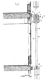
- a retractable louvre system 10 which comprises a top support member 12, a bottom support member 14, a plurality of flexible elongate louvre interconnecting elements 16, a plurality of louvres 18, and two elongate tensioning elements 20 (only one being shown).
- top and bottom support members 12 and 14 are attached to a suitable surface, typically a wall above or below a window, and comprise a bracket portion 22.
- the louvres 18 are interconnected by independent sets of the flexible elongate louvre interconnecting elements 16. Each independent set typically comprises four louvre interconnecting elements 16, preferably in the form of cables.
- the tail-end louvre 24 of the plurality of louvres 18 is suspended from the top bracket portion 22 of the top support member 12 by a first independent set 26 of the louvre interconnecting elements 16.
- Each following louvre 18 is suspended, in a similar fashion, from the immediately adjacent louvre 18 above by a second set 28 of the louvre interconnecting elements 16.
- the top bracket portion 22 includes two motorised spools 30 (only one shown in Figure 3) to which two louvre interconnecting elements 32 of the first set 26 are respectively attached.
- the two louvre interconnecting elements 32 typically support only the externally facing longitudinal edge 29 of the tail-end louvre, but may alternatively support the opposite longitudinal edge.
- a bearing guide surface 31, which may be a guide pulley, is also provided in the top bracket portion 22 to guide each louvre interconnecting element 32 as it is wound off and taken up by its spool 30.
- the elongate tensioning elements 20 are endless flexible elongate elements and extend along opposite transverse sides 34 of the louvres 18, perpendicularly or substantially perpendicularly to the longitudinal extent of the louvre 18 and in parallel or substantially in parallel with the major portion of the louvre interconnecting elements 16 when they are in tension.
- Top and bottom pulleys 36 and 38 are rotatably supported by the top and bottom bracket portions 22, respectively, and each endless tensioning element 20 is entrained around the respective pulleys 36 and 38 to provide a front run 40 and a back run 42.
- An electric motor 44 is mounted on the top bracket portion 22 and synchronously drives each top pulley 36.
- the bottom pulley 38 acts as a guide.
- the bottom bracket portion 22 is a tensioning bracket which has two screw-threaded shafts 46, which are received through part of the bottom support member 14, and two tension adjusting elements 48, typically being a nut and washer, each threadingly engaged with a respective shaft 46.
- the tension adjusting elements 48 when moved, move the tensioning bracket 22 relative to the bottom support member 14, which has the effect of adjusting the tension in the endless tensioning elements 20.
- a coiled spring 50 is also received on each shaft 46, interposed between the tension adjusting element 48 and the bottom support member 14.
- the coiled spring 50 provides acoustic damping.
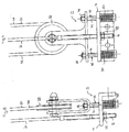
- a slide member 52 is supported on the transverse sides 34 for angular displacement relative to the transverse extent of the respective louvre 18.
- the slide member 52 includes two tubular receiving parts 54 and 56 through which the two runs 40 and 42 of each endless tensioning element 20 are respectively received.
- the slide member 52 also includes a through-bore 58 which passes through or substantially through the centre of rotation of the slide member 52, in parallel or substantially parallel with the tubular receiving parts 54 and 56, and through which an elongate guide member 60 is slidably received.
- the lead louvre 62 of the plurality of louvres 18 is fixedly attached to the front run 40 of each endless tensioning element 20. Attachment is effected by providing two screw-threaded fastening elements 64 which extend through the wall of the receiving part 54 and engage with the endless tensioning element 20.
- the other receiving part 56 of the slide member 52 of the lead louvre 62 is slidable on the back run 42 of each endless tensioning element 20.
- both receiving parts 54 and 56 of the slide members 52 of the remaining louvres 18 are slidable on the front and back runs 40 and 42 of the endless tensioning elements 20.
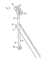
- the elongate guide member 60 is a flexible elongate member, typically a cable, which is attached to the tensioning bracket 22.
- the elongate guide member 60 has a screw-threaded end part 66 at each end (only one shown in Figures 4 and 5), and a second tension adjusting element 68 is threadingly engaged on the end part 66 to bear against the bottom support member 14.
- a similar arrangement (not shown) is provided on the top support member 12, and by moving one or both second tension adjusting elements 68, the guide member 60 can be suitably tensioned.
- the tension imparted to the guide member 60 typically exceeds that of the endless tensioning elements 20.
- the guide member 60 thus prevents the louvres 18 from drooping and/or swinging, especially when mounted, for example, horizontally or sideways and/or when externally mounted and subjected to environmental conditions, such as wind.
- each louvre 18 includes a plurality of bottomed-bores 70 (only one shown in Figure 7), an urging member, typically in the form of a compression spring 72, axially received and retained in each bore 70 by a retaining plate 74, and a guide element 76, which may be a pulley or a static or substantially static bearing surface, mounted adjacent to the opening of each bore 70.
- Each louvre interconnecting element 16 extends around the guide element 76 and into a respective bottomed-bore 70, coaxially with the spring 72.
- a stop 78 is positioned on the louvre interconnecting element 16, at or adjacent to the end received in the bore 70, and bears against the distal end 80 of the spring 72.
- the compression springs 72 are relatively lightly sprung so that the louvre interconnecting elements 16 are only drawn into the bores 70 when the louvres 18 are drawn towards each other.
- the front run 40 becomes a tensioning run in the direction of the bottom support member 14.
- the endless tensioning element 20, through the urging of the driven pulley 36, causes the louvre interconnecting elements 16 to be extracted from their respective bores 70 to a maximum or substantially maximum state and tensioned. In this state, when the motorised spools 30 wind off or take up the two louvre interconnecting elements 32, the angle of all of the louvres 18 is adjusted.
- the front run 40 becomes a retracting run in the direction of the top support member 12.
- the lead louvre 62 which is attached to the endless tensioning element 20, moves towards the top support member 12, it collects the remaining louvres 18 to form a stacked arrangement adjacent the top support member 12.
- the tension in each set of louvre interconnecting elements 16 decreases, due to the louvres 18 being moved towards each other, the louvre interconnecting elements 16 are drawn, by the compression springs 72, into the respective bores 70.
- the louvres 18 can be, typically opaque, solar shades, or can be glass or transparent / translucent laminates. They may range from 50 millimetres (mm) to 500 mm and above and be shaped as simple slats or aerofoil extrusions.
- the louvres 18 may also incorporate one or more photovoltaic cells (not shown) by which the incident external light can be utilised to generate a useful electric current to, for example, power internal lighting of a building.
- a self cleaning glass such as Pilkington Activ RTM may be incorporated into the louvres 18 along with the photovoltaic cell(s) to ensure a maximum amount of energy is obtained with minimal maintenance, i.e. cleaning of the surface of the louvre.
- the glass of the glass louvres 18 may incorporate a plastic sheet or film (not shown) which acts to refract external light into the building.
- This type of glass is known as Serraglaze RTM, and benefits buildings by increasing the amount of external light transmitted into a room, thereby reducing the need for additional or supplementary artificial lighting.
- the glass of the glass louvres 18 may alternatively or additionally incorporate a vapour deposited pyrolitic or hard coat, such as Pilkington Reflectafloat RTM or a Low-E coating (not shown).
- the Reflectafloat RTM and Low-E coating are a thin metallic coating on the glass which reflects a higher proportion of incident infra-red rays than plain or normal glass while allowing the transmission of visible light.
- the louvres 18 may thus be sealed units in order to incorporate such a feature.
- the endless tensioning element 20 is replaced by a non-continuous tensioning element 20'.
- the front run 40 is wound off and taken up by a first spool 82
- the back run 42 is wound off and taken up by a second spool 84.
- Both spools 82 and 84 are held on a common spindle 86, which is driven by the motor 44.
- retractable louvre system 10 can be positioned horizontally or sideways, and as such these terms should be construed accordingly.
- tensioning bracket 22, motorised spools 30, and pulley 36 and motor 44 could be positioned on the other support member.
- the bottom guide pulley 38 could be a static or substantially static bearing guide surface; and the top and bottom support members 12 and 14 may be independent of each other, or formed into a single continuous support member.
Landscapes
- Engineering & Computer Science (AREA)
- Structural Engineering (AREA)
- Civil Engineering (AREA)
- Architecture (AREA)
- Specific Sealing Or Ventilating Devices For Doors And Windows (AREA)
Abstract
Description
Claims (16)
- A retractable louvre system comprising one or more support members, a plurality of flexible elongate louvre interconnecting elements, a plurality of angularly displaceable louvres attached to the louvre interconnecting elements, and one or more elongate tensioning elements for tensioning the flexible louvre interconnecting elements and for retracting the louvres to form a stacked arrangement.
- A retractable louvre system as claimed in claim 1, wherein the elongate tensioning element is an endless flexible elongate element.
- A retractable louvre system as claimed in claim 2, wherein there are two said support members which are spaced from each other, the endless flexible elongate element being entrained around a motor-driven pulley mounted on one of the support members and a guide mounted on the other support member.
- A retractable louvre system as claimed in claim 1, wherein the elongate tensioning element is a flexible elongate element, the two ends of which are attached to separate spools driven by a motor.
- A retractable louvre system as claimed in claim 4, wherein there are two said support members which are spaced from each other, the separate spools being coaxially mounted on one of the support members, and the flexible elongate element being entrained around a guide mounted on the other support member.
- A retractable louvre system as claimed in any one of the preceding claims, wherein only the lead louvre of the plurality of louvres is fixedly attached to the elongate tensioning element.
- A retractable louvre system as claimed in claim 6 when dependent on claim 3 or claim 5, further comprising a tensioning bracket which has a screw-threaded shaft and which rotatably supports the guide, the screw-threaded shaft being received through one of the support members and being screw-threadingly engaged with a tension adjusting element which moves the bracket relative to the support member to adjust the tension in the elongate tensioning element.
- A retractable louvre system as claimed in claim 7, wherein the tensioning means also includes acoustic damping.
- A retractable louvre system as claimed in claim 8, wherein the acoustic damping is in the form of a spring interposed between the tension adjusting element and the support member.
- A retractable louvre system as claimed in any one of the preceding claims, wherein each louvre is attached to an adjacent louvre by an independent set of the louvre interconnecting elements, and the tail-end louvre is attached to one of the support members by one said independent set of the louvre interconnecting elements.
- A retractable louvre system as claimed in claim 10, wherein each louvre includes a spring mechanism for retracting the respective independent set of flexible elongate louvre interconnecting elements as the louvres are retracted.
- A retractable louvre system as claimed in claim 11, wherein the spring mechanism comprises a plurality of bores formed in each louvre, and a coiled spring axially retained in each bore, each flexible elongate louvre interconnecting element extending axially into a respective said bore and having a stop which is positioned at or adjacent to the end received in the bore and which bears against the distal end of the coiled spring, the coiled spring drawing the flexile elongate louvre interconnecting element into the bore when the louvres are retracted.
- A retractable louvre system as claimed in any one of claims 10 to 12, wherein the support member to which the tail-end louvre is attached includes a motorised spool by which the louvre interconnecting elements, which support one longitudinal edge of the tail-end louvre, can be wound off and taken up to adjust the angle of the louvres.
- A retractable louvre system as claimed in any one of the preceding claims, further comprising a plurality of slide members attached to the louvres and through which an elongate guide member is slidably received.
- A retractable louvre system as claimed in claim 14, wherein the elongate guide member is a flexible elongate member.
- A retractable louvre system as claimed in any one of the preceding claims, wherein the elongate tensioning element has a run which, when moved in one direction, acts as a tensioning run which tensions the louvre interconnecting elements and, when moved in the opposite direction, acts as a retracting run which retracts the louvres.
Applications Claiming Priority (2)
| Application Number | Priority Date | Filing Date | Title |
|---|---|---|---|
| GB0203818A GB2385370B (en) | 2002-02-19 | 2002-02-19 | A retractable louvre system |
| GB0203818 | 2002-02-19 |
Publications (2)
| Publication Number | Publication Date |
|---|---|
| EP1336714A2 true EP1336714A2 (en) | 2003-08-20 |
| EP1336714A3 EP1336714A3 (en) | 2004-03-17 |
Family
ID=9931301
Family Applications (1)
| Application Number | Title | Priority Date | Filing Date |
|---|---|---|---|
| EP03250966A Withdrawn EP1336714A3 (en) | 2002-02-19 | 2003-02-18 | A retractable louvre system |
Country Status (2)
| Country | Link |
|---|---|
| EP (1) | EP1336714A3 (en) |
| GB (1) | GB2385370B (en) |
Cited By (2)
| Publication number | Priority date | Publication date | Assignee | Title |
|---|---|---|---|---|
| WO2017086810A1 (en) * | 2015-11-20 | 2017-05-26 | "Moa" Spółka Cywilna | Photovoltaic louver |
| US10934770B2 (en) | 2016-07-20 | 2021-03-02 | Navus Consulting Cc | Slat for a blind and blind formed therefrom |
Families Citing this family (1)
| Publication number | Priority date | Publication date | Assignee | Title |
|---|---|---|---|---|
| GB0819728D0 (en) * | 2008-10-28 | 2008-12-03 | Turnils Uk Ltd | Privacy blinds and components thereof |
Family Cites Families (5)
| Publication number | Priority date | Publication date | Assignee | Title |
|---|---|---|---|---|
| DE1659966A1 (en) * | 1966-07-30 | 1969-11-20 | Herbert Heinemann | Wind guide for blinds |
| US4444239A (en) * | 1981-12-02 | 1984-04-24 | Haines Richard K | Venetian blind and frame for vehicles |
| JPS62117978A (en) * | 1985-02-26 | 1987-05-29 | ク−ロン株式会社 | Ceiling type blind |
| US5143135A (en) * | 1991-01-18 | 1992-09-01 | Levolor Corporation | Low profile headrail venetian blind |
| US6068039A (en) * | 1992-09-28 | 2000-05-30 | Judkins; Ren | Material for venetian type blinds |
-
2002
- 2002-02-19 GB GB0203818A patent/GB2385370B/en not_active Expired - Fee Related
-
2003
- 2003-02-18 EP EP03250966A patent/EP1336714A3/en not_active Withdrawn
Cited By (2)
| Publication number | Priority date | Publication date | Assignee | Title |
|---|---|---|---|---|
| WO2017086810A1 (en) * | 2015-11-20 | 2017-05-26 | "Moa" Spółka Cywilna | Photovoltaic louver |
| US10934770B2 (en) | 2016-07-20 | 2021-03-02 | Navus Consulting Cc | Slat for a blind and blind formed therefrom |
Also Published As
| Publication number | Publication date |
|---|---|
| GB2385370B (en) | 2005-04-27 |
| EP1336714A3 (en) | 2004-03-17 |
| GB2385370A (en) | 2003-08-20 |
| GB0203818D0 (en) | 2002-04-03 |
Similar Documents
| Publication | Publication Date | Title |
|---|---|---|
| US8324496B1 (en) | Low-profile single-axis tracker with wind mitigation | |
| US8959835B2 (en) | Window unit | |
| US10577859B2 (en) | Light-redirecting retractable window covering | |
| US11248763B2 (en) | High efficiency external daylighting devices | |
| US20150121760A1 (en) | Window unit | |
| CN113530041A (en) | Photovoltaic system curtain wall of energy-saving building | |
| EP1336714A2 (en) | A retractable louvre system | |
| US20200309337A1 (en) | Daylighting device | |
| KR102296902B1 (en) | Electric Roll blind | |
| GB2535506A (en) | Retractable blind system | |
| CN116856599B (en) | Energy-saving curtain wall for building | |
| CN220955390U (en) | Hollow built-in shutter with multiple layers of glass | |
| JP3311901B2 (en) | Control device for solar and radiant heat in window openings | |
| US20090194096A1 (en) | Method and apparatus for concentrating optical radiation using light trapping elements | |
| KR102575088B1 (en) | Solar panels driving system for reducing outdoor noise | |
| CN116599443A (en) | A solar power generation device adapting to the sun's irradiation angle | |
| EP4248559A1 (en) | Photovoltaic panel for balcony | |
| CN211478089U (en) | Lighting device of corundum-zirconia purity detection chamber | |
| GB2385369A (en) | Louvre system | |
| CN113757613A (en) | Energy-conserving natural lighting device for building based on thing networked control | |
| CN112647810A (en) | Building combined shading system based on optical reflection | |
| CN219061474U (en) | Solar power generation sunshade shutter curtain | |
| CN223867548U (en) | Adjustable sunshade reflecting device | |
| US11698174B2 (en) | Devices for internal daylighting with IR rejection | |
| CN221989745U (en) | Adjustable building exterior wall sunshade device |
Legal Events
| Date | Code | Title | Description |
|---|---|---|---|
| PUAI | Public reference made under article 153(3) epc to a published international application that has entered the european phase |
Free format text: ORIGINAL CODE: 0009012 |
|
| AK | Designated contracting states |
Designated state(s): AT BE BG CH CY CZ DE DK EE ES FI FR GB GR HU IE IT LI LU MC NL PT SE SI SK TR |
|
| AX | Request for extension of the european patent |
Extension state: AL LT LV MK RO |
|
| PUAL | Search report despatched |
Free format text: ORIGINAL CODE: 0009013 |
|
| AK | Designated contracting states |
Kind code of ref document: A3 Designated state(s): AT BE BG CH CY CZ DE DK EE ES FI FR GB GR HU IE IT LI LU MC NL PT SE SI SK TR |
|
| AX | Request for extension of the european patent |
Extension state: AL LT LV MK RO |
|
| RIC1 | Information provided on ipc code assigned before grant |
Ipc: 7E 06B 9/327 B Ipc: 7E 06B 9/302 B Ipc: 7E 06B 7/08 A |
|
| AKX | Designation fees paid | ||
| REG | Reference to a national code |
Ref country code: DE Ref legal event code: 8566 |
|
| STAA | Information on the status of an ep patent application or granted ep patent |
Free format text: STATUS: THE APPLICATION IS DEEMED TO BE WITHDRAWN |
|
| 18D | Application deemed to be withdrawn |
Effective date: 20040918 |