EP1336727A2 - Schalldämpfer - Google Patents
Schalldämpfer Download PDFInfo
- Publication number
- EP1336727A2 EP1336727A2 EP03250475A EP03250475A EP1336727A2 EP 1336727 A2 EP1336727 A2 EP 1336727A2 EP 03250475 A EP03250475 A EP 03250475A EP 03250475 A EP03250475 A EP 03250475A EP 1336727 A2 EP1336727 A2 EP 1336727A2
- Authority
- EP
- European Patent Office
- Prior art keywords
- partition plate
- projection
- projections
- muffler
- sound
- Prior art date
- Legal status (The legal status is an assumption and is not a legal conclusion. Google has not performed a legal analysis and makes no representation as to the accuracy of the status listed.)
- Withdrawn
Links
Images




Classifications
-
- F—MECHANICAL ENGINEERING; LIGHTING; HEATING; WEAPONS; BLASTING
- F01—MACHINES OR ENGINES IN GENERAL; ENGINE PLANTS IN GENERAL; STEAM ENGINES
- F01N—GAS-FLOW SILENCERS OR EXHAUST APPARATUS FOR MACHINES OR ENGINES IN GENERAL; GAS-FLOW SILENCERS OR EXHAUST APPARATUS FOR INTERNAL-COMBUSTION ENGINES
- F01N1/00—Silencing apparatus characterised by method of silencing
- F01N1/06—Silencing apparatus characterised by method of silencing by using interference effect
-
- F—MECHANICAL ENGINEERING; LIGHTING; HEATING; WEAPONS; BLASTING
- F01—MACHINES OR ENGINES IN GENERAL; ENGINE PLANTS IN GENERAL; STEAM ENGINES
- F01N—GAS-FLOW SILENCERS OR EXHAUST APPARATUS FOR MACHINES OR ENGINES IN GENERAL; GAS-FLOW SILENCERS OR EXHAUST APPARATUS FOR INTERNAL-COMBUSTION ENGINES
- F01N1/00—Silencing apparatus characterised by method of silencing
- F01N1/02—Silencing apparatus characterised by method of silencing by using resonance
-
- F—MECHANICAL ENGINEERING; LIGHTING; HEATING; WEAPONS; BLASTING
- F01—MACHINES OR ENGINES IN GENERAL; ENGINE PLANTS IN GENERAL; STEAM ENGINES
- F01N—GAS-FLOW SILENCERS OR EXHAUST APPARATUS FOR MACHINES OR ENGINES IN GENERAL; GAS-FLOW SILENCERS OR EXHAUST APPARATUS FOR INTERNAL-COMBUSTION ENGINES
- F01N1/00—Silencing apparatus characterised by method of silencing
- F01N1/08—Silencing apparatus characterised by method of silencing by reducing exhaust energy by throttling or whirling
- F01N1/089—Silencing apparatus characterised by method of silencing by reducing exhaust energy by throttling or whirling using two or more expansion chambers in series
-
- F—MECHANICAL ENGINEERING; LIGHTING; HEATING; WEAPONS; BLASTING
- F01—MACHINES OR ENGINES IN GENERAL; ENGINE PLANTS IN GENERAL; STEAM ENGINES
- F01N—GAS-FLOW SILENCERS OR EXHAUST APPARATUS FOR MACHINES OR ENGINES IN GENERAL; GAS-FLOW SILENCERS OR EXHAUST APPARATUS FOR INTERNAL-COMBUSTION ENGINES
- F01N2210/00—Combination of methods of silencing
- F01N2210/02—Resonance and interference
-
- F—MECHANICAL ENGINEERING; LIGHTING; HEATING; WEAPONS; BLASTING
- F01—MACHINES OR ENGINES IN GENERAL; ENGINE PLANTS IN GENERAL; STEAM ENGINES
- F01N—GAS-FLOW SILENCERS OR EXHAUST APPARATUS FOR MACHINES OR ENGINES IN GENERAL; GAS-FLOW SILENCERS OR EXHAUST APPARATUS FOR INTERNAL-COMBUSTION ENGINES
- F01N2210/00—Combination of methods of silencing
- F01N2210/04—Throttling-expansion and resonance
-
- F—MECHANICAL ENGINEERING; LIGHTING; HEATING; WEAPONS; BLASTING
- F01—MACHINES OR ENGINES IN GENERAL; ENGINE PLANTS IN GENERAL; STEAM ENGINES
- F01N—GAS-FLOW SILENCERS OR EXHAUST APPARATUS FOR MACHINES OR ENGINES IN GENERAL; GAS-FLOW SILENCERS OR EXHAUST APPARATUS FOR INTERNAL-COMBUSTION ENGINES
- F01N2210/00—Combination of methods of silencing
- F01N2210/06—Throttling-expansion and interference
-
- F—MECHANICAL ENGINEERING; LIGHTING; HEATING; WEAPONS; BLASTING
- F01—MACHINES OR ENGINES IN GENERAL; ENGINE PLANTS IN GENERAL; STEAM ENGINES
- F01N—GAS-FLOW SILENCERS OR EXHAUST APPARATUS FOR MACHINES OR ENGINES IN GENERAL; GAS-FLOW SILENCERS OR EXHAUST APPARATUS FOR INTERNAL-COMBUSTION ENGINES
- F01N2450/00—Methods or apparatus for fitting, inserting or repairing different elements
- F01N2450/22—Methods or apparatus for fitting, inserting or repairing different elements by welding or brazing
-
- F—MECHANICAL ENGINEERING; LIGHTING; HEATING; WEAPONS; BLASTING
- F01—MACHINES OR ENGINES IN GENERAL; ENGINE PLANTS IN GENERAL; STEAM ENGINES
- F01N—GAS-FLOW SILENCERS OR EXHAUST APPARATUS FOR MACHINES OR ENGINES IN GENERAL; GAS-FLOW SILENCERS OR EXHAUST APPARATUS FOR INTERNAL-COMBUSTION ENGINES
- F01N2490/00—Structure, disposition or shape of gas-chambers
- F01N2490/02—Two or more expansion chambers in series connected by means of tubes
-
- F—MECHANICAL ENGINEERING; LIGHTING; HEATING; WEAPONS; BLASTING
- F01—MACHINES OR ENGINES IN GENERAL; ENGINE PLANTS IN GENERAL; STEAM ENGINES
- F01N—GAS-FLOW SILENCERS OR EXHAUST APPARATUS FOR MACHINES OR ENGINES IN GENERAL; GAS-FLOW SILENCERS OR EXHAUST APPARATUS FOR INTERNAL-COMBUSTION ENGINES
- F01N2490/00—Structure, disposition or shape of gas-chambers
- F01N2490/02—Two or more expansion chambers in series connected by means of tubes
- F01N2490/06—Two or more expansion chambers in series connected by means of tubes the gases flowing longitudinally from inlet to outlet in opposite directions
-
- F—MECHANICAL ENGINEERING; LIGHTING; HEATING; WEAPONS; BLASTING
- F01—MACHINES OR ENGINES IN GENERAL; ENGINE PLANTS IN GENERAL; STEAM ENGINES
- F01N—GAS-FLOW SILENCERS OR EXHAUST APPARATUS FOR MACHINES OR ENGINES IN GENERAL; GAS-FLOW SILENCERS OR EXHAUST APPARATUS FOR INTERNAL-COMBUSTION ENGINES
- F01N2490/00—Structure, disposition or shape of gas-chambers
- F01N2490/08—Two or more expansion chambers in series separated by apertured walls only
Definitions
- the present invention relates in general to mufflers and more particularly to mufflers of a type that is suitable for use with an internal combustion engine to muffle or silence exhaust noise produced by the engine.
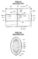
- Fig. 15 is a sectional view of the muffler and Fig. 16 is a sectional view taken along the line XVI-XVI of Fig. 15.
- the muffler comprises a semi-cylindrical outer case 301 having longitudinal ends 301a and 301b closed, and a regularly cylindrical inner case 302 installed in outer case 301 to extend longitudinally.
- Fig. 15 is a sectional view of the muffler
- Fig. 16 is a sectional view taken along the line XVI-XVI of Fig. 15.
- the muffler comprises a semi-cylindrical outer case 301 having longitudinal ends 301a and 301b closed, and a regularly cylindrical inner case 302 installed in outer case 301 to extend longitudinally.
- inner case 302 has a gas inlet part "IN” and a gas outlet part “OUT" at longitudinal ends.
- inner case 302 there are arranged front and rear inner sections 303 and 304, each having a cylindrical wall 302a with a plurality of small openings 303a and 304a.
- intermediate space section 306 that comprises a partition wall 305 formed with a plurality of small openings 306a.
- front and rear outer sections 403 and 404 that are separated by an intermediate space section 308 that comprises a partition wall 307 formed with a plurality of small openings 308a.
- exhaust gas from an associated engine enters front inner section 303 through gas inlet part "IN".
- One part of gas in front inner section 303 is led to rear inner section 304 through intermediate space section 306 and discharged to open air through gas outlet part "OUT", while the remaining part of gas in front inner section 303 is led into front outer section 403 through small openings 303a, into rear outer section 404 through small openings 308a, into rear inner section 304 through small openings 304a and discharged to open air through gas outlet part "OUT".
- acoustic energy or noise of the exhaust gas is reduced or damped due to expansion/resonance effect possessed by the gas flow passages.
- Laid-open Japanese Patent Applications (Tokkaihei) 7-13573 and 7-175485 show a sound insulating structure that is used as an under cover of an engine room of a motor vehicle for blocking noises of exhaust system of the engine from being emitted to open air. That is, for blocking noises of exhaust system, the sound insulting structure employs an acoustically improved mechanism.
- Laid-open Japanese Patent Application (Tokkaihei) 11-132024 shows a muffler that is produced by practically employing the acoustically improved mechanism of the above-mentioned publications 7-13573 and 7-175485.
- a muffler which comprises a case having opposed ends closed; a partition structure installed in the case to constitute a sound silencing path; inlet and outlet pipes incorporated with the sound silencing path; and a sound shielding wall structure installed in the case to constitute a part of the sound silencing path, wherein the sound shielding wall structure comprises first and second partition plates; a positioning structure that puts the first and second partition plates together to keep a given distance therebetween; a first group of projections defined by the first partition plate and projected toward the second partition plate, each projection of the first group having a first opening formed therethrough; and a second group of projections defined by the second partition plate and projected toward the first partition plate, each projection of the second group having a second opening formed therethrough, the projections of the second group respectively facing the projections of the first group having a given clearance kept therebetween.
- a muffler which comprises a case having opposed ends closed; at least one partition plate installed in the case to divide an interior of the same into two chambers; a sound shielding wall structure installed in one of the two chambers to divide the same into first and second sound chambers allowing the other one of the two chambers to serve as a third sound chamber; and pipe members projected into the case passing through the partition plate and the sound shielding wall structure to define in the case a sound silencing path including the first, second and third sound chambers, wherein the sound shielding wall structure comprises first and second partition plates; a positioning structure that puts the first and second partition plates together to keep a given distance therebetween; a first group of projections defined by the first partition plate and projected toward the second partition plate, each projection of the first group having a first opening formed therethrough; and a second group of projections defined by the second partition plate and projected toward the first partition plate, each projection of the second group having a second opening formed therethrough, the projections of the second group
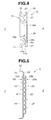
- FIG. 1 to 6 there is shown a muffler 50 according to the present invention.
- muffler 50 comprises a cylindrical outer case 2 that has longitudinal ends 3 and 4 closed.
- front and rear plates are welded to longitudinal open ends of outer case 2 to constitute the closed ends 3 and 4.
- the closed ends 3 and 4 will be referred to as front and rear plates for ease of description. Furthermore, for easy understanding, the portion of outer case 2 where front plate 3 is provided will be referred to as front portion of muffler 50, and the portion of outer case 2 where rear plate 4 is provided will be referred to as rear portion of muffler 50.
- first and third sound chambers 7 and 9 are respectively provided at the front and rear portions of muffler 50, and second sound chamber 8 is placed between first and third sound chambers 7 and 9.
- Sound shielding wall structure 5 generally comprises first and second circular partition plates 10 and 20 which are put on each other in an after-mentioned manner.
- inlet pipe 31 is inserted into outer case 2 from the front portion in a manner to pass through front plate 3 and sound shielding wall structure 5. As shown, inlet pipe 31 extends along a given axis eccentric to a center axis of outer case 2 and has an open inner end 31a exposed to second sound chamber 8.
- inlet pipe 31 is connected to an exhaust part of an associated engine through an exhaust pipe.
- a shorter resonator pipe 32 is held by partition plate 6 to extend along the given axis of inlet pipe 31.
- Resonator pipe 32 has front and rear open ends exposed to second and third sound chambers 8 and 9, so that second and third sound chambers 8 and 9 are communicated through resonator pipe 32.
- An outlet pipe 33 is inserted into outer case 2 from the rear portion in a manner to pass through rear plate 4, partition plate 6, and sound shielding wall structure 5.
- outlet pipe 33 extends along another given axis eccentric to the center axis "0" of outer case 2. More specifically, inlet pipe 31 and outlet pipe 33 are arranged symmetrically with respect to an imaginary plane X1 that includes the center axis "0" and extends along the same.
- outlet pipe 33 has an open inner end 33a exposed to first sound chamber 7 and has an open outer end exposed to open air.
- the wall structure 5 comprises generally first and second circular partition plates 10 and 20 that are put on each other.
- first partition plate 10 has an outer diameter identical to an inner diameter of outer case 2. As is seen from Figs. 1 and 5, first partition plate 10 comprises a main portion 11 that has a cylindrical peripheral edge 12 that is directed forward to be neatly received in outer case 2.
- main portion 11 is formed with supporting portions 13 and 14 for supporting inlet and outlet pipes 31 and 33 respectively. Furthermore, main portion 11 is formed with a plurality of openings 15a and a positioning projection (no numeral). As will be described hereinafter, the positioning projection is used for achieving relative positioning between first and second partition plates 10 and 20. As is seen from Fig. 3, each opening 15a of main portion 11 is defined in a rearward projected portion formed on main portion 11.
- cylindrical peripheral edge 12 of first partition plate 10 is spot-welded to the inner wall of outer case 2.
- second partition plate 20 of sound shielding wall structure 5 has a diameter that is smaller than that of first partition plate 10.
- a main portion 21 of second partition plate 20 is formed with supporting portions 23 and 24 for supporting inlet and outlet pipes 31 and 33 respectively. Furthermore, main portion 21 is formed with a plurality of openings 25a and a positioning projection 26. As will be described hereinafter, the positioning projection 26 is used for achieving the relative positioning between first and second partition plates 10 and 20.
- each opening 25a of main portion 21 is defined in a forward projected portion formed on main portion 21.
- a circular peripheral edge 22 of main portion 21 is spot-welded to a peripheral portion of a rear surface of main portion 11 of first partition plate 10.
- main portions 21 and 11 of second and first partition plates 20 and 10 are spaced apart by a certain distance. More specifically, as is seen from Fig. 3, a leading edge of each rearward projected portion (15) of first partition plate 10 and that of each forward projected portion (25) of second partition plate 20 are spaced apart by a predetermined distance L .
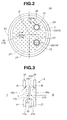
- Fig. 3 is an enlarged, partial and sectional view taken along the line III-III of Fig. 2.
- first and second partition plates 10 and 20 are formed with first and second groups of projections 15 and 25 each having an opening 15a or 25a. That is, each of first group of projections 15 of first partition plate 10 and that of second group of projections 25 of second partition plate 20 are arranged to face each other keeping the given distance L therebetween.
- projections 15 and 25 (or openings 15a and 25a) formed in first and second partition plates 10 and 20 are arranged to have a given distribution suitable for obtaining a desired performance.
- each rearward projection 15 of first partition plate 10 and corresponding forward projection 25 of second partition plate 20 faces each other with a space of width L kept therebetween.
- the space is denoted by numeral 40 in Fig. 3.
- the opening 15a of each rearward projection 15 of first partition plate 10 is coaxial with the opening 25a of the corresponding forward projection 25 of second partition plate 20. That is, the openings 15a and 25a of first and second partition plates 10 and 20 are communicated through the space 40.
- each opening 15a or 25a of first or second partition plate 10 or 20 is of a cylindrical shape having a smoothly curved inner wall 11b or 21b.
- a radius of curvature possessed by each opening 15a or 25a is denoted by R in the drawing. Due to provision of such smoothly curved inner walls 11b and 21b, exhaust gas flow from second sound chamber 8 to first sound chamber 7 is smoothly made, which suppresses or at least minimizes any noise produced when the gas flows in openings 25a and 15a. Furthermore, by the same reason, undesired separation of gas flow and construction flow, such as those described in Laid-open Japanese Patent Application (Tokkaihei) 11-132024, are suppressed or at least minimized.
- Fig. 4 is an enlarged, partial and sectional view taken along the line IV-IV of Fig. 2.
- first partition plate 10 is formed with a positioning projection 16 that projects rearward.
- Positioning projection 16 has an opening 16a formed therethrough.
- Second partition plate 20 is formed with a positioning projection 26 that projects forward.
- Projection 26 has an opening 26 formed therethrough.
- Projection 26 of second partition plate 20 is press-fitted into opening 16a of positioning projection 16 of first partition plate 10. That is, positioning projection 16 of first partition plate 10 projects rearward from a rear surface 11a of mail portion 11 of the same, and projection 26 of second partition plate 20 projects forward from a front surface 21a of main portion 21 thereof. More specifically, as is seen from the drawing, positioning projection 16 is constructed to have a rounded bank portion 16b that projects rearward. It is to be noted that opening 16a of positioning projection 16 has an oval shape.
- projection 26 of second partition plate 20 has an oval cross-section and has an oval opening 26a formed therethrough. That is, due to matching in shape, projection 26 of second partition plate 20 is intimately fitted in opening 16a of first partition plate 10 thereby to achieve a relative positioning between first and second partition plates 10 and 20.
- the front surface 21a of second partition plate 20 abuts against a top 16c of rounded bank portion 16b of first partition plate 10, as shown. Due to provision of the mutually engaged projections 16 and 26, openings 15a and 25a of first and second partition plates 10 and 20 precisely face to one another.
- the positioning projections 16 and 26 are provided at given portions of first and second partition plates 10 and 20 where the plates 10 and 20 are subjected to a primary vibration of resonance. With this measure, undesired noise caused by the resonance is suppressed or at least minimized.
- positioning projections 16 and 26 are placed on an imaginary line X1 at a position (26, 16) that is opposite to a position where the line X1 and another imaginary line Y1 passing through central portions of supporting portions 23 and 24 that support inlet and outlet pipes 31 and 33 intersect at right angles, the line X1 being a line that passes through the center axis "0" of outer case 2 and is perpendicular to the imaginary line Y1.
- first and second partition plates 10 and 20 are coupled together having positioning projection 26 of second plate 20 press-fitted into the positioning opening 16a of first plate 10. Then, as is seen from Fig. 6, the circular peripheral edge 22 of second plate 20 is spot-welded to the peripheral portion of the rear surface of first plate 10. With these steps, sound shielding wall structure 5 is produced.
- each opening 15a of first plate 10 faces the corresponding opening 25a of second plate 20 keeping a certain distance L therebetween.
- inlet pipe 31 is connected to an exhaust part of an associated internal combustion engine through an exhaust pipe, and outlet pipe 33 has the open end exposed to the open air.
- exhaust gas is led into muffler 2 through inlet pipe 31.
- inlet pipe 31 there is produced a pulsation flow of exhaust gas.
- the exhaust gas is led into second sound chamber 8 at first.
- a part of the gas is led into third sound chamber 9 through resonator pipe 32.
- the greater part of the gas in second sound chamber 8 is led into first sound chamber 7 through the openings 15a, 25a and 26a of sound insulating wall structure 5, and led into the open air through outlet pipe 33.
- the following modification 5A of sound shielding wall structure 5 may be employed in muffler 50 of the invention.
- openings 15a and 25a of first and second partition plates 10 and 20 may be directly connected without producing a clearance L therebetween.
- openings 25a (or 15a) illustrated by hatched circles are those that leave the clearance L
- openings 25a (or 15a) illustrated by blank circles are those that have no clearance L .
- these two types of openings 25a (or 15a) are uniformly distributed.
- the openings 25a (or 15a) that have no clearance L' may have the same construction as the above-mentioned positioning opening 26a (or 16a) of positioning projection 26 (or 16). That is, a so-called male-female connection is made between the openings 25a and 15a.
- a so-called male-female connection is made between the openings 25a and 15a.
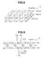
- FIG. 8 there is diagrammatically shown sound shielding wall structure 5 provided by muffler 50 of the invention.
- Fig. 9 shows a vibration model for explaining the acoustic mechanism established by the sound shielding wall structure 5.
- the sound shielding wall structure 5 comprises first and second partition plates 101 and 102 that correspond to the above-mentioned first and second partition plates 20 and 10 respectively. These two plates 101 and 102 are spaced from each other by the distance L .
- Each plate 101 or 102 has a plurality of openings 101a or 102a, which correspond to 25a or 15a of the above-mentioned plates 20 and 10. As shown, the openings 101a are arranged to face the openings 102a respectively.
- first and second partition plates 101 and 102 can exhibit a sound shielding effect when they are vibrated at a frequency higher than a resonance frequency.
- the acoustic system can be adjusted to shield a noise having a specified frequency. That is, in the present invention, sound shielding wall structure 5 installed in outer case 2 practically uses the acoustic mechanism of Fig. 9.
- FIG. 10 there is schematically shown the modification of the shielding wall structure 5.
- Fig. 11 shows a vibration model for explaining the acoustic mechanism established in the modification.
- first and second partition plates 151 and 152 constitute a single structure.
- incident wave is separately treated by these two vibration systems. That is, one part of incident wave entering the single factor vibration system provides a transmitted wave having the same phase as the incident wave. While, the other part of incident wave entering the double factor vibration system provides a transmitted wave having a phase differing from that of the incident wave by 180 degrees. This means that the transmitted wave from the single factor vibration system and that from the double factor vibration system cancel out each other, and thus an appropriate sound shielding effect is obtained from the modification.
- FIGs. 12, 13,and 14 there are shown other modifications 5B, 5C,and 5D of sound shielding wall structure 5 which may be employed in muffler 50 of the invention. As will become apparent from the following description, these modifications 5B, 5C,and 5D have different structures on positioning projections 16 and 26 of first and second partition plates 10 and 20.
- a positioning projection 55 possessed by second partition plate 20 is substantially the same as the above-mentioned positioning projection 26 of second partition plate 20 (see Fig. 4). While, a positioning projection 51 possessed by first partition plate 10 is different from the above-mentioned positioning projection 16 of first partition plate 10 (see Fig. 4). That is, in this modification 5B, positioning projection 51 has an annular leading end 51b that is directed toward second partition plate 20. Upon assembly, positioning projection 55 is intimately thrust into an opening 51a of positioning projection 51, as shown. With this, an opening 55a of positioning projection 55 provides a fluid communication between first and second sound chambers 7 and 8.
- first and second partition plates 10 and 20 Upon insertion of positioning projection 55 into opening 51a, the annular leading end 51b abuts against a root portion of positioning projection 55 thereby separating first and second partition plates 10 and 20 away from each other by a distance that is enough for keeping the predetermined distance L between the leading edge of each rearward projected portion 15 (see Fig. 3) of first partition plate 10 and that of corresponding forward projected portion 25 of second partition plate 20.
- a positioning projection 65 possessed by second partition plate 20 has a stepped portion 65b, and a positioning projection 61 possessed by first partition plate 10 has an annular leading end 61b that is directed away from second partition plate 20.
- an annular leading portion 65a of positioning projection 65 is intimately thrust into an opening 61a of positioning projection 61 from the back of first partition plate 10, as shown.
- an opening 65c of positioning projection 65 provides a fluid communication between first and second sound chambers 7 and 8.
- stepped portion 65b of positioning projection 65 abuts against the rear surface of first partition plate 10 thereby separating first and second partition plates 10 and 20 away from each other by a distance that is enough for keeping the predetermined distance L between the leading edge of each rearward projected portion 15 (see Fig. 3) of first partition plate 10 and that of corresponding forward projected portion 25 of second partition plate 20.
- a positioning projection 65 possessed by second partition plate 20 is substantially the same as that shown in Fig. 13. While, a positioning projection 61 is different from that shown in Fig. 13. That is, in this modification 5D, positioning projection 61 is provided with an annular raised portion 61b that is directed toward second partition plate 20. Upon assembly, an annular leading portion 65a of positioning projection 65 is intimately thrust into an opening 61a of positioning projection 61 from the back of first partition plate 10, as shown. With this, an opening 65c of positioning projection 65 provides a fluid communication between first and second sound chambers 7 and 8.
- stepped portion 65b of positioning portion 65 abuts against a top of the annular raised portion 61b of first partition plate 10, thereby separating first and second partition plates 10 and 20 away from each other by a distance that is enough for keeping the predetermined distance L between the leading edge of each rearward projected portion 15 (see Fig. 3) of first partition plate 10 and that of corresponding forward projected portion 25 of second partition plate 20.
- positioning structure which comprises positioning projections 16 and 26, 51 and 55, and 61 and 65.
- two or more positioning structures may be employed for achieving much assured relative positioning between first and second partition plates 10 and 20.
- the positioning opening 16a of positioning projection 16 of first partition plate 10 may have a triangular shape, rectangular shape, or the like, that is, an angled shape other than the above-mentioned oval shape.
Landscapes
- Engineering & Computer Science (AREA)
- Chemical & Material Sciences (AREA)
- Combustion & Propulsion (AREA)
- Mechanical Engineering (AREA)
- General Engineering & Computer Science (AREA)
- Exhaust Silencers (AREA)
Applications Claiming Priority (2)
| Application Number | Priority Date | Filing Date | Title |
|---|---|---|---|
| JP2002040636 | 2002-02-18 | ||
| JP2002040636A JP2003239717A (ja) | 2002-02-18 | 2002-02-18 | 消音装置 |
Publications (2)
| Publication Number | Publication Date |
|---|---|
| EP1336727A2 true EP1336727A2 (de) | 2003-08-20 |
| EP1336727A3 EP1336727A3 (de) | 2003-10-29 |
Family
ID=27621482
Family Applications (1)
| Application Number | Title | Priority Date | Filing Date |
|---|---|---|---|
| EP03250475A Withdrawn EP1336727A3 (de) | 2002-02-18 | 2003-01-27 | Schalldämpfer |
Country Status (3)
| Country | Link |
|---|---|
| US (1) | US6705429B2 (de) |
| EP (1) | EP1336727A3 (de) |
| JP (1) | JP2003239717A (de) |
Cited By (3)
| Publication number | Priority date | Publication date | Assignee | Title |
|---|---|---|---|---|
| EP1959106A1 (de) * | 2007-02-13 | 2008-08-20 | J. Eberspächer GmbH & Co. KG | Schalldämpfer für eine Abgasanlage |
| ITVI20080274A1 (it) * | 2008-11-19 | 2010-05-20 | Ima Saf S P A | Silenziatore perfezionato |
| WO2012055949A1 (de) * | 2010-10-28 | 2012-05-03 | Avl List Gmbh | Abgasschalldämpferanordnung |
Families Citing this family (6)
| Publication number | Priority date | Publication date | Assignee | Title |
|---|---|---|---|---|
| JP4392592B2 (ja) * | 2003-12-12 | 2010-01-06 | トヨタ自動車株式会社 | 排気消音装置 |
| US20080023264A1 (en) * | 2006-07-27 | 2008-01-31 | Pacini Larry W | Muffler having adjustable butterfly valve for improved sound attenuation and engine performance |
| US8443933B2 (en) * | 2009-06-23 | 2013-05-21 | Tenneco Gmbh | Tubular acoustic insulating element |
| US9874125B2 (en) | 2013-10-10 | 2018-01-23 | Miratech Group, Llc | Quadruple-tuned silencer apparatus and method for attenuating sound from an engine exhaust |
| DE102016101693A1 (de) * | 2016-02-01 | 2017-08-03 | Eberspächer Exhaust Technology GmbH & Co. KG | Schalldämpfer für eine Abgasanlage |
| CN113464256A (zh) * | 2021-07-19 | 2021-10-01 | 重庆嘉扬实业有限公司 | 一种使5Kw机组发电机功率提升的椭圆筒体直排消音器 |
Citations (3)
| Publication number | Priority date | Publication date | Assignee | Title |
|---|---|---|---|---|
| JPH0713573A (ja) | 1993-03-17 | 1995-01-17 | Nissan Motor Co Ltd | 遮音板及び車両の遮音構造 |
| JPH07175485A (ja) | 1993-12-21 | 1995-07-14 | Nissan Motor Co Ltd | 遮音壁構造 |
| JPH09125930A (ja) | 1995-11-07 | 1997-05-13 | Nissan Motor Co Ltd | 排気系消音器 |
Family Cites Families (12)
| Publication number | Priority date | Publication date | Assignee | Title |
|---|---|---|---|---|
| US4192402A (en) * | 1977-05-27 | 1980-03-11 | Honda Giken Kogyo Kabushiki Kaisha | Muffler for internal combustion engines |
| DE2908506C2 (de) * | 1979-03-05 | 1985-01-31 | Roth Technik GmbH, 7560 Gaggenau | Schalldämpfer für Verbrennungskraftmaschinen |
| JPS6176714A (ja) * | 1984-09-20 | 1986-04-19 | Mitsubishi Electric Corp | 内燃機関用排気消音装置 |
| JPH0712650Y2 (ja) * | 1989-02-23 | 1995-03-29 | マツダ株式会社 | エンジンの排気サイレンサ |
| US5614699A (en) | 1994-05-09 | 1997-03-25 | Nissan Motor Co., Ltd. | Automobile exhaust noise suppressor |
| JP3379254B2 (ja) * | 1994-12-26 | 2003-02-24 | 日産自動車株式会社 | 排気消音装置 |
| JP3153731B2 (ja) * | 1995-05-17 | 2001-04-09 | ユニプレス株式会社 | 遮音壁構造 |
| US5823600A (en) | 1996-01-24 | 1998-10-20 | Nissan Motor Co., Ltd. | Noise insulating wall structure |
| JP3119192B2 (ja) * | 1997-03-07 | 2000-12-18 | 日産自動車株式会社 | 遮音板構造 |
| JP3119193B2 (ja) * | 1997-03-07 | 2000-12-18 | 日産自動車株式会社 | 遮音板構造 |
| US5912442A (en) * | 1997-07-02 | 1999-06-15 | Trw Inc. | Structure having low acoustically-induced vibration response |
| JPH11132024A (ja) * | 1997-10-30 | 1999-05-18 | Isuzu Motors Ltd | 消音器 |
-
2002
- 2002-02-18 JP JP2002040636A patent/JP2003239717A/ja active Pending
-
2003
- 2003-01-27 EP EP03250475A patent/EP1336727A3/de not_active Withdrawn
- 2003-01-27 US US10/351,434 patent/US6705429B2/en not_active Expired - Fee Related
Patent Citations (3)
| Publication number | Priority date | Publication date | Assignee | Title |
|---|---|---|---|---|
| JPH0713573A (ja) | 1993-03-17 | 1995-01-17 | Nissan Motor Co Ltd | 遮音板及び車両の遮音構造 |
| JPH07175485A (ja) | 1993-12-21 | 1995-07-14 | Nissan Motor Co Ltd | 遮音壁構造 |
| JPH09125930A (ja) | 1995-11-07 | 1997-05-13 | Nissan Motor Co Ltd | 排気系消音器 |
Cited By (3)
| Publication number | Priority date | Publication date | Assignee | Title |
|---|---|---|---|---|
| EP1959106A1 (de) * | 2007-02-13 | 2008-08-20 | J. Eberspächer GmbH & Co. KG | Schalldämpfer für eine Abgasanlage |
| ITVI20080274A1 (it) * | 2008-11-19 | 2010-05-20 | Ima Saf S P A | Silenziatore perfezionato |
| WO2012055949A1 (de) * | 2010-10-28 | 2012-05-03 | Avl List Gmbh | Abgasschalldämpferanordnung |
Also Published As
| Publication number | Publication date |
|---|---|
| JP2003239717A (ja) | 2003-08-27 |
| US20030155175A1 (en) | 2003-08-21 |
| US6705429B2 (en) | 2004-03-16 |
| EP1336727A3 (de) | 2003-10-29 |
Similar Documents
| Publication | Publication Date | Title |
|---|---|---|
| JPH088305Y2 (ja) | 消音器 | |
| US6752240B1 (en) | Sound attenuator for a supercharged marine propulsion device | |
| US7219764B1 (en) | Exhaust muffler | |
| CN102686840A (zh) | 内燃机的排气装置 | |
| EP1010868B1 (de) | Querstromschalldämpfer mit Leitblechen | |
| EP1336727A2 (de) | Schalldämpfer | |
| JP3331266B2 (ja) | 不等長の2本の上流排気管の下流排気管との接続用コネクタ | |
| CN209838498U (zh) | 用于车辆的排气系统、谐振器及消声器系统 | |
| JP2011027038A (ja) | マフラ | |
| JP2006009667A (ja) | 消音器用排圧感応型制御バルブ | |
| US20230203973A1 (en) | Vehicle exhaust system | |
| US11639676B2 (en) | Vehicle exhaust system | |
| JP4261711B2 (ja) | 排気消音装置 | |
| JP2020159305A (ja) | 消音器 | |
| JP7244284B2 (ja) | 消音器及び排気管 | |
| JPH08170518A (ja) | 消音器 | |
| JPS5943456Y2 (ja) | 消音器 | |
| JPH0861173A (ja) | 消音装置 | |
| JP2001020718A (ja) | 消音器用バルブ装置 | |
| JPH11182226A (ja) | 自動二輪車の排気マフラー | |
| JPH1162548A (ja) | パイプの消音構造 | |
| JPH11109979A (ja) | 消音装置 | |
| CN121205758A (zh) | 消音器 | |
| CN116146319A (zh) | 用于降低驻波的排气系统调谐器管 | |
| JPH0687617U (ja) | 消音器 |
Legal Events
| Date | Code | Title | Description |
|---|---|---|---|
| PUAI | Public reference made under article 153(3) epc to a published international application that has entered the european phase |
Free format text: ORIGINAL CODE: 0009012 |
|
| 17P | Request for examination filed |
Effective date: 20030226 |
|
| AK | Designated contracting states |
Designated state(s): AT BE BG CH CY CZ DE DK EE ES FI FR GB GR HU IE IT LI LU MC NL PT SE SI SK TR |
|
| AX | Request for extension of the european patent |
Extension state: AL LT LV MK RO |
|
| PUAL | Search report despatched |
Free format text: ORIGINAL CODE: 0009013 |
|
| AK | Designated contracting states |
Kind code of ref document: A3 Designated state(s): AT BE BG CH CY CZ DE DK EE ES FI FR GB GR HU IE IT LI LU MC NL PT SE SI SK TR |
|
| AX | Request for extension of the european patent |
Extension state: AL LT LV MK RO |
|
| AKX | Designation fees paid |
Designated state(s): DE FR GB |
|
| 17Q | First examination report despatched |
Effective date: 20040827 |
|
| 17Q | First examination report despatched |
Effective date: 20040827 |
|
| GRAP | Despatch of communication of intention to grant a patent |
Free format text: ORIGINAL CODE: EPIDOSNIGR1 |
|
| STAA | Information on the status of an ep patent application or granted ep patent |
Free format text: STATUS: THE APPLICATION IS DEEMED TO BE WITHDRAWN |
|
| 18D | Application deemed to be withdrawn |
Effective date: 20110405 |