EP1336768B1 - Dispositif et procédé pour commander un arbre d'entraínement automatisé d'une automobile - Google Patents
Dispositif et procédé pour commander un arbre d'entraínement automatisé d'une automobile Download PDFInfo
- Publication number
- EP1336768B1 EP1336768B1 EP02003754A EP02003754A EP1336768B1 EP 1336768 B1 EP1336768 B1 EP 1336768B1 EP 02003754 A EP02003754 A EP 02003754A EP 02003754 A EP02003754 A EP 02003754A EP 1336768 B1 EP1336768 B1 EP 1336768B1
- Authority
- EP
- European Patent Office
- Prior art keywords
- control unit
- clutch
- safety signal
- control apparatus
- engine
- Prior art date
- Legal status (The legal status is an assumption and is not a legal conclusion. Google has not performed a legal analysis and makes no representation as to the accuracy of the status listed.)
- Expired - Lifetime
Links
- 238000000034 method Methods 0.000 title claims description 14
- 230000005540 biological transmission Effects 0.000 claims description 33
- 238000012806 monitoring device Methods 0.000 claims description 14
- 238000002485 combustion reaction Methods 0.000 claims description 5
- 230000006854 communication Effects 0.000 description 4
- 238000004891 communication Methods 0.000 description 4
- 230000008878 coupling Effects 0.000 description 4
- 238000010168 coupling process Methods 0.000 description 4
- 238000005859 coupling reaction Methods 0.000 description 4
- 238000005096 rolling process Methods 0.000 description 4
- 230000001419 dependent effect Effects 0.000 description 2
- 230000000994 depressogenic effect Effects 0.000 description 2
- 230000007257 malfunction Effects 0.000 description 2
- 230000008901 benefit Effects 0.000 description 1
- 230000007175 bidirectional communication Effects 0.000 description 1
- 230000008859 change Effects 0.000 description 1
- 230000007423 decrease Effects 0.000 description 1
- 238000010586 diagram Methods 0.000 description 1
- 238000002347 injection Methods 0.000 description 1
- 239000007924 injection Substances 0.000 description 1
- 238000004519 manufacturing process Methods 0.000 description 1
- 230000008569 process Effects 0.000 description 1
- 230000004044 response Effects 0.000 description 1
Images


Classifications
-
- F—MECHANICAL ENGINEERING; LIGHTING; HEATING; WEAPONS; BLASTING
- F16—ENGINEERING ELEMENTS AND UNITS; GENERAL MEASURES FOR PRODUCING AND MAINTAINING EFFECTIVE FUNCTIONING OF MACHINES OR INSTALLATIONS; THERMAL INSULATION IN GENERAL
- F16D—COUPLINGS FOR TRANSMITTING ROTATION; CLUTCHES; BRAKES
- F16D48/00—External control of clutches
- F16D48/06—Control by electric or electronic means, e.g. of fluid pressure
-
- F—MECHANICAL ENGINEERING; LIGHTING; HEATING; WEAPONS; BLASTING
- F16—ENGINEERING ELEMENTS AND UNITS; GENERAL MEASURES FOR PRODUCING AND MAINTAINING EFFECTIVE FUNCTIONING OF MACHINES OR INSTALLATIONS; THERMAL INSULATION IN GENERAL
- F16D—COUPLINGS FOR TRANSMITTING ROTATION; CLUTCHES; BRAKES
- F16D2500/00—External control of clutches by electric or electronic means
- F16D2500/10—System to be controlled
- F16D2500/104—Clutch
- F16D2500/10406—Clutch position
- F16D2500/10412—Transmission line of a vehicle
-
- F—MECHANICAL ENGINEERING; LIGHTING; HEATING; WEAPONS; BLASTING
- F16—ENGINEERING ELEMENTS AND UNITS; GENERAL MEASURES FOR PRODUCING AND MAINTAINING EFFECTIVE FUNCTIONING OF MACHINES OR INSTALLATIONS; THERMAL INSULATION IN GENERAL
- F16D—COUPLINGS FOR TRANSMITTING ROTATION; CLUTCHES; BRAKES
- F16D2500/00—External control of clutches by electric or electronic means
- F16D2500/30—Signal inputs
- F16D2500/306—Signal inputs from the engine
- F16D2500/3067—Speed of the engine
-
- F—MECHANICAL ENGINEERING; LIGHTING; HEATING; WEAPONS; BLASTING
- F16—ENGINEERING ELEMENTS AND UNITS; GENERAL MEASURES FOR PRODUCING AND MAINTAINING EFFECTIVE FUNCTIONING OF MACHINES OR INSTALLATIONS; THERMAL INSULATION IN GENERAL
- F16D—COUPLINGS FOR TRANSMITTING ROTATION; CLUTCHES; BRAKES
- F16D2500/00—External control of clutches by electric or electronic means
- F16D2500/30—Signal inputs
- F16D2500/31—Signal inputs from the vehicle
- F16D2500/3108—Vehicle speed
-
- F—MECHANICAL ENGINEERING; LIGHTING; HEATING; WEAPONS; BLASTING
- F16—ENGINEERING ELEMENTS AND UNITS; GENERAL MEASURES FOR PRODUCING AND MAINTAINING EFFECTIVE FUNCTIONING OF MACHINES OR INSTALLATIONS; THERMAL INSULATION IN GENERAL
- F16D—COUPLINGS FOR TRANSMITTING ROTATION; CLUTCHES; BRAKES
- F16D2500/00—External control of clutches by electric or electronic means
- F16D2500/30—Signal inputs
- F16D2500/314—Signal inputs from the user
- F16D2500/31406—Signal inputs from the user input from pedals
- F16D2500/31426—Brake pedal position
-
- F—MECHANICAL ENGINEERING; LIGHTING; HEATING; WEAPONS; BLASTING
- F16—ENGINEERING ELEMENTS AND UNITS; GENERAL MEASURES FOR PRODUCING AND MAINTAINING EFFECTIVE FUNCTIONING OF MACHINES OR INSTALLATIONS; THERMAL INSULATION IN GENERAL
- F16D—COUPLINGS FOR TRANSMITTING ROTATION; CLUTCHES; BRAKES
- F16D2500/00—External control of clutches by electric or electronic means
- F16D2500/30—Signal inputs
- F16D2500/314—Signal inputs from the user
- F16D2500/31406—Signal inputs from the user input from pedals
- F16D2500/3144—Accelerator pedal position
-
- F—MECHANICAL ENGINEERING; LIGHTING; HEATING; WEAPONS; BLASTING
- F16—ENGINEERING ELEMENTS AND UNITS; GENERAL MEASURES FOR PRODUCING AND MAINTAINING EFFECTIVE FUNCTIONING OF MACHINES OR INSTALLATIONS; THERMAL INSULATION IN GENERAL
- F16D—COUPLINGS FOR TRANSMITTING ROTATION; CLUTCHES; BRAKES
- F16D2500/00—External control of clutches by electric or electronic means
- F16D2500/50—Problem to be solved by the control system
- F16D2500/51—Relating safety
- F16D2500/5108—Failure diagnosis
-
- F—MECHANICAL ENGINEERING; LIGHTING; HEATING; WEAPONS; BLASTING
- F16—ENGINEERING ELEMENTS AND UNITS; GENERAL MEASURES FOR PRODUCING AND MAINTAINING EFFECTIVE FUNCTIONING OF MACHINES OR INSTALLATIONS; THERMAL INSULATION IN GENERAL
- F16D—COUPLINGS FOR TRANSMITTING ROTATION; CLUTCHES; BRAKES
- F16D2500/00—External control of clutches by electric or electronic means
- F16D2500/50—Problem to be solved by the control system
- F16D2500/51—Relating safety
- F16D2500/5114—Failsafe
Definitions
- the present invention relates to a control device for an automated powertrain of a motor vehicle, wherein the powertrain an engine, in particular an internal combustion engine, a transmission, in particular a spur gear, and a separating clutch arranged between the engine and the transmission wherein the control device is a main control unit and a clutch control unit connected to the main control unit having an actuator for the separating clutch, wherein the main control unit to a safety signal the clutch control unit transmits according to which the clutch control unit the separating clutch controls, if a defined Error occurs.
- the present invention relates to a corresponding Method for controlling an automated drive train.
- Such a control device or such a control method are known.
- this control device corresponds the safety signal of the speed of the motor. If the engine is stationary, the separating clutch is closed, otherwise opened.
- the disadvantage of these simple devices is that that in case of failure does not respond optimally in all driving situations can be.
- DE 198 07 764 A1 discloses a control unit for a Automated start-up clutch of a motor vehicle manual transmission.
- the clutch control unit is connected via a CAN bus with the engine control in connection.
- the control unit ensures in a normal mode of operation for the vehicle to come on running engine, gear engaged and accelerator pedal not operated "Creeps". If an error o.ä. is detected in a Switched emergency mode in which the control unit the "Ankriechen" prevented.
- From DE 44 41 896 A1 is a control concept for the drive train a motor vehicle known.
- a motor control and a transmission controller for a torque converter or a continuously variable transmissions are interconnected via a communication bus connected.
- the engine control includes functional units for transmission control, the data of the engine and the Chassis are dependent, such. a switching point selection control, and provide the transmission control input signals.
- An emergency device detects when communication over the bus is disturbed. Then the transmission control turns on other input signals to, for example, on manual signals. In other words, a driver becomes a bus failure indicated that he must switch by hand.
- the document DE 199 47 025 A1 relates to a single drive device for a powertrain.
- the powertrain includes an internal combustion engine, a starting clutch and automated Manual transmission.
- a second Software procedure checks the generated control parameters Admissibility.
- the second procedure can be used as a redundancy procedure be executed. Alternatively, the second procedure checks the Control requirements of the first procedure based on other scales. If the second procedure detects that one of the first Procedure generated by default is not allowed, security measures taken.
- a control device or a control method having the features of the preamble of the claims 1 and 16 is known from EP-A-808 253.
- the object of the present invention Invention therein, a control device or a control method for an automated powertrain, in which the emergency conditions are improved.
- This object is achieved with the aforementioned control device or the control method mentioned above achieved in that the main control unit is adapted to the safety signal based on a plurality of vehicle state variables to create.
- the clutch control unit in emergency operation after finding the defined error case (hereinafter short "error"), for example, in case of failure of the processor the clutch control unit (or in the event of a malfunction of the Communication link between the main control unit and the clutch control unit), the separating clutch better adapted to control the present at the fault condition of the vehicle.
- error the defined error case
- the main control unit thus generates regularly, preferably continuously the safety signal based on the Plurality of vehicle state variables such that the security signal always optimally adapted to the condition of the vehicle.
- This safety signal is regular, preferably continuously (or quasi-continuous) to the clutch control unit transfer.
- the clutch control unit therefore has at any time a redundant information about the vehicle condition, the is based on a plurality of vehicle state variables and thus more differentiated than known systems in which the safety signal is just a single sensor signal, i.e. the engine speed signal passed from the main control unit is.
- the error that occurs, for example, to an error in a transmission / clutch control main processor act or disrupt the communication link between the main control unit and the clutch control unit. It is also conceivable that the clutch control unit, the separating clutch based on the last received security signal if, for example, the main control unit Total failed.
- the security signal is a two-valued signal.
- the safety signal decreases one of N different values, where N> 2.
- the safety signal is dependent from the plurality of vehicle state variables "more accurate", so there is the current state of the vehicle more accurate.
- the clutch control unit the separating clutch in dependence on the safety signal either opens or closes.
- the clutch control unit the separating clutch in dependence of the Safety signal opens, closes or enters a grinding state brings.
- this embodiment in particular find a multi-valued (N> 2) safety signal application can.
- the main clutch / transmission processor fails possible, the separating clutch (acc the type of bypass) by means of the main control unit.
- the separating clutch acc the type of bypass
- the main control unit therefore, in case of error even a start from standstill possible, for example to drive away from a railroad track in an emergency situation.
- the clutch control unit has no special Include logic to control the disconnect clutch.
- the "Intelligence" of the control takes over in such a case the main control unit.
- the plurality includes of vehicle state variables, the engine speed.
- the Plurality of vehicle state variables the vehicle speed.
- the Plurality of vehicle state variables the accelerator pedal position.
- the plurality includes vehicle state variables according to a further preferred embodiment the Brake pedal position.
- Such bus systems are particularly suitable for use in Motor vehicles.
- connection between the Main control unit and clutch control unit also exclusive be realized by the bus.
- the security signal from the main control unit to the clutch control unit transmitted via a separate line.
- some redundancy is provided by sending the safety signal to the clutch control unit can be transmitted, even if the bus connection is disturbed.
- the security signal is a frequency signal whose frequency is from the plurality of Vehicle state variables depends.
- Such a signal can be on the side of the main control unit generate comparatively easily and on the side of the Evaluate clutch control unit relatively easily.
- the Clutch control unit a processor device and a monitoring device on, wherein the monitoring device the Safety signal is received immediately and is designed to to drive the actuator directly.
- the clutch control unit is so constructed that an emergency operation is possible even if the main processor of the clutch control unit has failed.
- Fig. 1 is a control device according to the invention in general denoted by 10.
- the control device 10 has a motor control unit 12 and a transmission control unit 14.
- the control device 10 is used to an automated To drive powertrain of a motor vehicle, ie the actuators used for automation coordinated with each other to press.
- the engine control unit 12 and the transmission control unit 14 are in the motor vehicle usually locally separated.
- the engine control unit 12 is a total of the powertrain a main control unit, and the transmission control unit 14 both for controlling actuators of the transmission (for and laying out of gears) as well as for driving a separating clutch suitable.
- Control device 10 can be controlled. These include in particular dual-clutch transmission.
- An engine speed sensor 16 is connected to the engine control unit 12, the engine control unit 12 with the current Motor speed 17 supplied. Accordingly, a vehicle speed sensor 18 for transmitting the current vehicle speed 19 connected, an accelerator pedal position sensor 20 for transmitting the current accelerator pedal position 21 (or in the simplest case of a bivalent signal concerning the accelerator operation) and a brake pedal position sensor 22 for transmitting a brake pedal position 23 (or in the simpler Case of a bivalent brake actuation signal).
- the sensor signals 17, 19, 21 and 23 are from an interface device 24 of the engine control unit 12 processed and to a processor device 26 (a main processor of the engine control unit 12).
- the processor device 26 is connected via a CAN interface 28 to a CAN bus 30.
- a CAN interface 32 is also provided the CAN bus 30 is connected.
- the engine control unit 12 further includes a security signal interface 34, which is connected to a connecting line 36 is.
- the transmission control unit 14 has a Security signal interface 38, which also with the Connecting line 36 is connected.
- the transmission control unit 14 is also a processor device 40 provided (a main processor of the transmission control unit 14).
- the processor device 40 is connected with the CAN interface 32 and the safety signal interface 38th
- the transmission control unit 14 has a clutch valve driver 42 for generating a clutch drive signal 43 for an actuator for actuating the separating clutch and a Monitoring device 44 on.
- the clutch valve driver 42 is connected to the processor device 40 and with the monitoring device 44 in connection.
- the monitoring device 44 is connected to the safety signal interface 38 connected and is in bidirectional communication connection with the processor device 40.
- the engine control unit 12 generally serves the engine (Internal combustion engine) of the motor vehicle to control, in particular Set ignition timing, injection quantities, etc. Off For clarity, these functions of the engine control unit 12 not shown in Fig. 1.
- the transmission control unit 14 is designed to via suitable driver actuators of the transmission of the To drive motor vehicle, which for clarity in Fig. 1 also not shown.
- the engine control unit 12 serves the transmission control unit 14, for example, with vehicle state information etc., depending on the illustrated Vehicle condition sensors 16, 18, 20, 22, and possibly further such sensors and derived quantities. After all the engine control unit 12 must respond in response to a request the transmission control unit 14, the engine torque during the gear change operation, partly driver-independent, steer.
- the operation of the separating clutch is for the driving safety of the of such a vehicle of significant importance.
- the separating clutch is used in a conventional manner to the Drive wheels to connect to the engine or from this decouple.
- the significance of the coupling function be mentioned that when the vehicle is stationary and the engine is running maybe only the clutch open the vehicle the unwanted driving away. That's why it is of great importance that when a fault occurs ensures the safety increasing operation of the clutch becomes.
- a safety signal over the line 36 to transmit only the engine speed. If the engine speed is less than a predetermined threshold (below idle speed), which means that the Engine is off, the disconnect clutch is closed. This will cause unintentional rolling away in the event of being switched off Motors avoided. If the engine speed is greater is the threshold, the clutch is opened. hereby prevents the vehicle from unintentionally starting. While however, when driving, the occurrence of a fault is safety-critical. Because in such a case, the engine speed usually greater than the threshold. If so, then the clutch For example, it may become an unexpected event Loss of drive power during an overtaking process come.
- a predetermined threshold below idle speed
- the security signal however, generated from a plurality of vehicle state variables.
- safe state This allows a safe state of the motor vehicle (“safe state ”) are realized in all operating situations, as is described below with reference to an exemplary embodiment will be.
- the monitoring device 44 monitors the operation of the processor device 40. If the processor device 40 of any Reasons in a faulty state device (be it due to a fault of its own, a malfunction on the CAN bus or similar), the monitoring device 44 "bypasses" the processor device 40 and uses the transmitted over the connecting line 36 Safety signal to off, the clutch valve driver 42 to drive immediately.
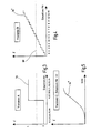
- Fig. 2 shows a table 50 in which 16 different combinations of states of the four sensors 16, 18, 20 and 22 are.
- 0 - 15 is on safety signal generated by the engine control unit 12 a first embodiment shown.
- this embodiment it is a two-valued signal that is either 0 (Clutch closed) or 1 (clutch open) can be.
- the described generation of the safety signal is shown in FIG. 3 schematically as a representation of a frequency above the respective Situation or status number shown.
- the security signal 54 for the states 0, 1, 2, 3, 6, 10 and 14 in each case assumes the value 0, then that the clutch is closed.
- the safety signal assumes the value 1, so that the clutch is opened.
- Safety signal 54 is a frequency signal that in the cases the states No. 0, 1, 2, 3, 6, 10 and 14 a certain frequency owns, and in the other states a different frequency having.
- the monitoring device 44 detects the frequency of the security signal 54 and evaluates them logically.
- FIG. 4 shows an alternative embodiment in which the security signal 54 'is multi-valued.
- each individual state becomes one assigned to certain frequency of the security signal 54 '.
- the Monitor 44 judges by a threshold 60, whether one of the states 0, 1, 2, 3, 6, 10, 14 is present (Frequency below threshold 60) to the disconnect clutch to close, or one of the other states.
- Fig. 2 is in the right of the two columns "safe coupling state" an alternative embodiment for the production a security signal shown.
- the clutch becomes in the states Nos. 0 to 9 and 11 to 15 are controlled identically as in the first Embodiment. Only in the state No. 10, if namely the engine is running and the vehicle is stationary, but the driver is Accelerator pedal is operated by the engine control unit 12 instead of a Signal "Close clutch” generates a safety signal 54 ", as shown for example in Fig. 5.
- the security signal 54 "is in the case of the state No. 10 is a time-variable signal that initiates a startup pretends. Consequently, in this state, the safety signal 54 "directly from the monitoring device 44 are used, a “gentle” starting perform. Because the monitoring device 44 only needs a signal proportional to the safety signal 54 " forward the clutch valve driver 42. Accordingly, it is not necessary, in the monitoring device 44 a complex To provide "intelligence". A few are enough Logic gates.
- the security signal 54 is preferably a frequency signal is, it can also be a voltage, a current, a PWM or a similar signal act.
Landscapes
- Engineering & Computer Science (AREA)
- General Engineering & Computer Science (AREA)
- Physics & Mathematics (AREA)
- Fluid Mechanics (AREA)
- Mechanical Engineering (AREA)
- Control Of Driving Devices And Active Controlling Of Vehicle (AREA)
- Hydraulic Clutches, Magnetic Clutches, Fluid Clutches, And Fluid Joints (AREA)
Claims (16)
- Dispositif de commande (10) pour une ligne d'entraínement automatisée d'un véhicule automobile, la ligne d'entraínement comportant un moteur, en particulier un moteur à combustion interne, une boíte de vitesses, en particulier un réducteur à engrenages droits, et un embrayage de séparation monté entre le moteur et la boíte de vitesses, le dispositif de commande (10) comportant une unité de commande principale (12) et une unité de commande d'embrayage (14), qui est reliée à l'unité de commande principale (12) et qui active un actionneur (42) pour l'embrayage de séparation, l'unité de commande principale (12) transmettant un signal de sécurité (54) vers l'unité de commande d'embrayage (14), selon lequel l'unité de commande d'embrayage (14) active l'embrayage de séparation à l'apparition d'un dysfonctionnement défini,
caractérisé en ce que l'unité de commande principale (12) génère le signal de sécurité (54) sur la base d'une pluralité de variables d'état du véhicule (17, 19, 21, 23). - Dispositif de commande selon la revendication 1, caractérisé en ce que le signal de sécurité (54) est un signal bivalent.
- Dispositif de commande selon la revendication 1, caractérisé en ce que le signal de sécurité (54') peut accepter une valeur parmi N valeurs différentes, N étant supérieur à 2.
- Dispositif de commande selon la revendication 2 ou 3, caractérisé en ce que l'unité de commande d'embrayage (14) ouvre ou ferme l'embrayage de séparation en fonction du signal de sécurité (54 ; 54').
- Dispositif de commande selon la revendication 3, caractérisé en ce que l'unité de commande d'embrayage (14), en fonction du signal de sécurité (54"), ouvre, ferme ou amène en position de friction l'embrayage de séparation.
- Dispositif de commande selon la revendication 5, caractérisé en ce que l'unité de commande d'embrayage (14) génère un signal de commande d'embrayage (43) proportionnel à la valeur du signal de sécurité (54").
- Dispositif de commande selon l'une quelconque des revendications 1 à 6, caractérisé en ce que la pluralité de variables d'état du véhicule contient la vitesse de rotation du moteur (17).
- Dispositif de commande selon l'une quelconque des revendications 1 à 7, caractérisé en ce que la pluralité de variables d'état du véhicule contient la vitesse du véhicule (19).
- Dispositif de commande selon l'une quelconque des revendications 1 à 8, caractérisé en ce que la pluralité de variables d'état du véhicule contient la position de la pédale d'accélérateur (21).
- Dispositif de commande selon l'une quelconque des revendications 1 à 9, caractérisé en ce que la pluralité de variables d'état du véhicule contient la position de la pédale de frein (23).
- Dispositif de commande selon l'une quelconque des revendications 1 à 10, caractérisé en ce que la liaison (30) entre l'unité de commande principale (12) et l'unité de commande d'embrayage (14) est formée par un bus (30), en particulier un bus CAN (30).
- Dispositif de commande selon la revendication 11, caractérisé en ce que le signal de sécurité est transmis via le bus.
- Dispositif de commande selon la revendication 11, caractérisé en ce que le signal de sécurité (54) est transmis de l'unité de commande principale (12) vers l'unité de commande d'embrayage (14) via une ligne séparée (36).
- Dispositif de commande selon l'une quelconque des revendications 1 à 13, caractérisé en ce que le signal de sécurité (54) est un signal de fréquence, dont la fréquence (P) dépend de la pluralité des variables d'état du véhicule (17, 19, 21, 23).
- Dispositif de commande selon l'une quelconque des revendications 1 à 14, caractérisé en ce que l'unité de commande d'embrayage (14) comporte un processeur (40) et un contrôleur (44), le contrôleur (44) recevant directement le signal de sécurité (54) et étant conçu pour activer directement l'actionneur.
- Procédé de commande d'une ligne d'entraínement automatisée d'un véhicule automobile, la ligne d'entraínement comportant un moteur, en particulier un moteur à combustion interne, une boíte de vitesses, en particulier un réducteur à engrenages droits, et un embrayage de séparation monté entre le moteur et la boíte de vitesses, un dispositif de commande (10) comportant une unité de commande principale (12) et une unité de commande d'embrayage (14), qui est reliée à l'unité de commande principale (12) et qui active un actionneur (42) pour l'embrayage de séparation, l'unité de commande principale (12) transmettant un signal de sécurité (54) vers l'unité de commande d'embrayage (14), selon lequel l'unité de commande d'embrayage (14) active l'embrayage de séparation à l'apparition d'un dysfonctionnement défini,
caractérisé en ce que l'unité de commande principale (12) génère le signal de sécurité (54) sur la base d'une pluralité de variables d'état du véhicule (17, 19, 21, 23).
Priority Applications (2)
| Application Number | Priority Date | Filing Date | Title |
|---|---|---|---|
| DE50204519T DE50204519D1 (de) | 2002-02-19 | 2002-02-19 | Vorrichtung und Verfahren zum Steuern eines automatisierten Antriebsstranges eines Kraftfahrzeuges |
| EP02003754A EP1336768B1 (fr) | 2002-02-19 | 2002-02-19 | Dispositif et procédé pour commander un arbre d'entraínement automatisé d'une automobile |
Applications Claiming Priority (1)
| Application Number | Priority Date | Filing Date | Title |
|---|---|---|---|
| EP02003754A EP1336768B1 (fr) | 2002-02-19 | 2002-02-19 | Dispositif et procédé pour commander un arbre d'entraínement automatisé d'une automobile |
Publications (2)
| Publication Number | Publication Date |
|---|---|
| EP1336768A1 EP1336768A1 (fr) | 2003-08-20 |
| EP1336768B1 true EP1336768B1 (fr) | 2005-10-12 |
Family
ID=27619157
Family Applications (1)
| Application Number | Title | Priority Date | Filing Date |
|---|---|---|---|
| EP02003754A Expired - Lifetime EP1336768B1 (fr) | 2002-02-19 | 2002-02-19 | Dispositif et procédé pour commander un arbre d'entraínement automatisé d'une automobile |
Country Status (2)
| Country | Link |
|---|---|
| EP (1) | EP1336768B1 (fr) |
| DE (1) | DE50204519D1 (fr) |
Families Citing this family (1)
| Publication number | Priority date | Publication date | Assignee | Title |
|---|---|---|---|---|
| DE102014223002A1 (de) * | 2014-11-11 | 2016-05-12 | Robert Bosch Gmbh | Verfahren zum sicheren Betreiben eines Kraftfahrzeugs |
Family Cites Families (5)
| Publication number | Priority date | Publication date | Assignee | Title |
|---|---|---|---|---|
| JPS62299435A (ja) * | 1986-06-19 | 1987-12-26 | Isuzu Motors Ltd | 異常検出装置付き車両の制御装置 |
| DE4441896B4 (de) | 1994-11-24 | 2009-10-08 | Continental Automotive Gmbh | Steuerung für ein Kraftfahrzeug |
| DE19544021A1 (de) * | 1995-11-25 | 1997-05-28 | Bosch Gmbh Robert | Steuerungssystem |
| NO980709L (no) | 1997-02-27 | 1998-08-28 | Luk Getriebe Systeme Gmbh | Motorvogn |
| DE19947025A1 (de) | 1999-09-21 | 2001-03-22 | Mannesmann Sachs Ag | Verfahren zum Ansteuern eines Antriebssystems eines Fahrzeugs |
-
2002
- 2002-02-19 EP EP02003754A patent/EP1336768B1/fr not_active Expired - Lifetime
- 2002-02-19 DE DE50204519T patent/DE50204519D1/de not_active Expired - Lifetime
Also Published As
| Publication number | Publication date |
|---|---|
| DE50204519D1 (de) | 2005-11-17 |
| EP1336768A1 (fr) | 2003-08-20 |
Similar Documents
| Publication | Publication Date | Title |
|---|---|---|
| DE10237167B4 (de) | Verfahren zur Steuerung eines automatisierten Schaltgetriebes | |
| EP1219489B1 (fr) | Système et procédé de commande et/ou surveillance d'un ensemble comportant au moins deux contrôleurs | |
| EP2131075B1 (fr) | Système et procédé de fonctionnement d'un boîte de vitesses robotisée en cas de panne d'un capteur de régime moteur ou d'une liaison de bus entre des modules de commandes | |
| DE19807764A1 (de) | Kraftfahrzeug | |
| DE102016202828A1 (de) | Antriebssystem für ein Hybridfahrzeug sowie Verfahren zum Betreiben eines solchen Antriebssystems | |
| DE19815260A1 (de) | Kraftfahrzeug | |
| DE10340529A1 (de) | Verfahren, Vorrichtung und deren Verwendung zum Betrieb eines Kraftfahrzeuges | |
| DE19829861A1 (de) | Kraftfahrzeug | |
| DE19732924B4 (de) | Verfahren zur Steuerung einer automatisierten Kupplung | |
| EP1554503A2 (fr) | Procede et systeme de commande d'au moins un actionneur dans la chaine cinematique d'un vehicule | |
| EP3084253B1 (fr) | Procédé destiné à augmenter la disponibilité d'un embrayage de coupure hybride dans le groupe motopropulseur hybride d'un véhicule à moteur | |
| DE102008014495A1 (de) | Verfahren und Vorrichtung zur Steuerung eines Antriebsstrangs eines Fahrzeugs | |
| DE19719615B4 (de) | Vorrichtung zur automatisierten Betätigung eines Drehmomentübertragungssystems | |
| EP1516768A2 (fr) | Procédé de commande d'un système de traction d'une automobile | |
| EP0928379B1 (fr) | Embrayage automatique | |
| EP1336768B1 (fr) | Dispositif et procédé pour commander un arbre d'entraínement automatisé d'une automobile | |
| WO2002085660A1 (fr) | Procede de reconnaissance d'un conducteur et systeme de commande pour vehicule a embrayage automatise | |
| DE102015223595B4 (de) | Verfahren zum Ankoppeln eines Nebenabtriebes | |
| DE19815258B4 (de) | Kraftfahrzeug mit einem Getriebe und einer Vorrichtung zur Steuerung einer automatisierten Kupplung | |
| EP1662185B1 (fr) | Procédé et système de commande pour interrompre en toute sécurité la transmission dans la chaine cinématique | |
| DE19960334A1 (de) | Kraftfahrzeug | |
| WO2012076214A1 (fr) | Procédé et dispositif de commande d'une chaîne cinématique de véhicule automobile | |
| DE10236541B4 (de) | Verfahren zum Betrieb eines Kraftfahrzeuges | |
| DE102009039504A1 (de) | Verfahren zur Fehlererkennung in einem Antriebsstrang | |
| DE102005034522A1 (de) | Kraftfahrzeug mit einer Bremseinrichtung und Verfahren zum Steuern einer Bremseinrichtung |
Legal Events
| Date | Code | Title | Description |
|---|---|---|---|
| PUAI | Public reference made under article 153(3) epc to a published international application that has entered the european phase |
Free format text: ORIGINAL CODE: 0009012 |
|
| 17P | Request for examination filed |
Effective date: 20020814 |
|
| AK | Designated contracting states |
Designated state(s): AT BE CH CY DE DK ES FI FR GB GR IE IT LI LU MC NL PT SE TR |
|
| AX | Request for extension of the european patent |
Extension state: AL LT LV MK RO SI |
|
| AKX | Designation fees paid |
Designated state(s): DE FR GB |
|
| GRAP | Despatch of communication of intention to grant a patent |
Free format text: ORIGINAL CODE: EPIDOSNIGR1 |
|
| GRAS | Grant fee paid |
Free format text: ORIGINAL CODE: EPIDOSNIGR3 |
|
| GRAA | (expected) grant |
Free format text: ORIGINAL CODE: 0009210 |
|
| AK | Designated contracting states |
Kind code of ref document: B1 Designated state(s): DE FR GB |
|
| REG | Reference to a national code |
Ref country code: GB Ref legal event code: FG4D Free format text: NOT ENGLISH |
|
| GBT | Gb: translation of ep patent filed (gb section 77(6)(a)/1977) |
Effective date: 20051012 |
|
| REF | Corresponds to: |
Ref document number: 50204519 Country of ref document: DE Date of ref document: 20051117 Kind code of ref document: P |
|
| ET | Fr: translation filed | ||
| PLBE | No opposition filed within time limit |
Free format text: ORIGINAL CODE: 0009261 |
|
| STAA | Information on the status of an ep patent application or granted ep patent |
Free format text: STATUS: NO OPPOSITION FILED WITHIN TIME LIMIT |
|
| 26N | No opposition filed |
Effective date: 20060713 |
|
| REG | Reference to a national code |
Ref country code: FR Ref legal event code: PLFP Year of fee payment: 15 |
|
| REG | Reference to a national code |
Ref country code: FR Ref legal event code: PLFP Year of fee payment: 16 |
|
| REG | Reference to a national code |
Ref country code: FR Ref legal event code: PLFP Year of fee payment: 17 |
|
| PGFP | Annual fee paid to national office [announced via postgrant information from national office to epo] |
Ref country code: FR Payment date: 20210120 Year of fee payment: 20 |
|
| PGFP | Annual fee paid to national office [announced via postgrant information from national office to epo] |
Ref country code: GB Payment date: 20210129 Year of fee payment: 20 Ref country code: DE Payment date: 20210113 Year of fee payment: 20 |
|
| REG | Reference to a national code |
Ref country code: DE Ref legal event code: R071 Ref document number: 50204519 Country of ref document: DE |
|
| REG | Reference to a national code |
Ref country code: GB Ref legal event code: PE20 Expiry date: 20220218 |
|
| PG25 | Lapsed in a contracting state [announced via postgrant information from national office to epo] |
Ref country code: GB Free format text: LAPSE BECAUSE OF EXPIRATION OF PROTECTION Effective date: 20220218 |