EP1336802B1 - Schwenkbares Heizelement für elektrisches Gargerät - Google Patents
Schwenkbares Heizelement für elektrisches Gargerät Download PDFInfo
- Publication number
- EP1336802B1 EP1336802B1 EP03010549A EP03010549A EP1336802B1 EP 1336802 B1 EP1336802 B1 EP 1336802B1 EP 03010549 A EP03010549 A EP 03010549A EP 03010549 A EP03010549 A EP 03010549A EP 1336802 B1 EP1336802 B1 EP 1336802B1
- Authority
- EP
- European Patent Office
- Prior art keywords
- heater element
- heating element
- working position
- cooking appliance
- end portions
- Prior art date
- Legal status (The legal status is an assumption and is not a legal conclusion. Google has not performed a legal analysis and makes no representation as to the accuracy of the status listed.)
- Expired - Lifetime
Links
- 238000010411 cooking Methods 0.000 title claims description 29
- 238000010438 heat treatment Methods 0.000 title abstract description 82
- 238000004140 cleaning Methods 0.000 description 3
- CPLXHLVBOLITMK-UHFFFAOYSA-N Magnesium oxide Chemical compound [Mg]=O CPLXHLVBOLITMK-UHFFFAOYSA-N 0.000 description 2
- 235000021168 barbecue Nutrition 0.000 description 2
- 230000009897 systematic effect Effects 0.000 description 2
- 238000002788 crimping Methods 0.000 description 1
- 230000000593 degrading effect Effects 0.000 description 1
- 230000005484 gravity Effects 0.000 description 1
- 239000000395 magnesium oxide Substances 0.000 description 1
- 238000004519 manufacturing process Methods 0.000 description 1
- 239000000463 material Substances 0.000 description 1
- 239000002184 metal Substances 0.000 description 1
Images


Classifications
-
- F—MECHANICAL ENGINEERING; LIGHTING; HEATING; WEAPONS; BLASTING
- F24—HEATING; RANGES; VENTILATING
- F24C—DOMESTIC STOVES OR RANGES ; DETAILS OF DOMESTIC STOVES OR RANGES, OF GENERAL APPLICATION
- F24C7/00—Stoves or ranges heated by electric energy
- F24C7/06—Arrangement or mounting of electric heating elements
Definitions
- the present invention relates to the field of electric cooking appliances type furnaces or any type of appliance used for cooking grills or roasts (grill, barbecue ...) and relates to an electric cooking appliance according to the preamble of claim 1.
- Such an apparatus is known from FR 2,720,917.
- Document FR 2 720 917 discloses a heating element for an electric household appliance, movable by means of a guide element making it possible to move the heating element from a working position to a position of pivoting clearance. around a loop. If this solution is well adapted to a position of the heating element at the level of the hearth of the oven, it is appropriate, in a vault use of the heating element, to provide a specific system for holding the heating element in a horizontal position. working.
- the document FR 2 752 918 describes a pivotable furnace resistance, the mounting of said resistor being carried out by means of holes made in each of the side walls, the resistor being pivotally mounted around a tilting axis passing through said holes.
- Each hole carries a fixed mounted bearing, in which is mounted journaling a sheath portion of the corresponding free end of the resistor to allow the pivoting of the resistor.
- An elastic means allows to recall the resistance in its working position, horizontal.
- One of the objects of the present invention is to overcome the disadvantages of the prior art by providing a pivoting heating element for an electric cooking appliance which is easy to produce and implement, in order to reduce manufacturing costs, without degrading the functionality of the heating element, and while allowing simple manipulation of the heating element for the user.
- an electric cooking appliance comprising a frame comprising at least one bottom wall and / or an arch wall, at least one side wall, defining a cooking chamber, at least one tubular heating element arranged in the cooking chamber, in the vicinity of the vault and / or the sole of the electrical appliance, said heating element being able to be positioned, by rotation, firstly in a horizontal working position, and on the other hand in a position of disengagement with respect to said working position, characterized in that said heating element comprises two end parts whose free ends are connected by connectors to an electric circuit for supplying the heating element, said end portions extending out of the cooking chamber through an opening in one of the side walls and each having at least one protrusion substantially adjacent to the side wall to limit the deflections by rotation and / or translation of said heating element.
- the protrusion formed on the end portions of the heating element is obtained by stamping the heating element under a press.
- the stamping creates a flattening of the heating element, and therefore a transverse expansion thereof, enlargement proper to retain the heating element in its deflections.
- the cooking appliance comprises a frame 3 and a heating element 10 of the shielded type.
- the different parts of the frame 3, shown in FIG. 1, consist of a vault 5 secured to lateral walls 4 and / or a rear wall 7, thus delimiting a cooking chamber 2.
- An access door, not shown , allows to realize a closed cooking chamber of an electric oven 1.
- the heating element 10 extends in a substantially horizontal plane of extension, in the vicinity of the vault 5 when said heating element 10 is in a working position, where the electric appliance is fed to carry out cooking.
- One of the side walls 4 of the oven has two openings 8 through which the heating element 10 passes through said side wall 4, such as Figure 2.
- This side wall can be completed by a cross member 6 to stiffen the entire oven.
- the heating element 10 is arranged in a zigzag manner in order to distribute the radiated power as well as possible.
- the parts of the heating element located outside the cooking chamber are designated by the reference 11 and referred to as the end portions.
- the end portions By extreme part, here is meant a portion of the heating element 10 having the very end of this element and a portion of the heating element extending from the end of the heating element to the side wall 4, the length of this end portion being up to about 10% of the total length of the heating element.
- These two end portions of the heating element are located on the same side of one of the two side walls and substantially at the same height in the oven.
- end parts 11 are arranged elastic return means 16 of the heating element 10 to enable it to occupy a horizontal working position, while offering the possibility, by biasing the elastic means 16, to make pivoting the heating element 10 in order to clean the vault or sole adjoining the heating element 10.
- the pivoting of the heating element 10 is carried out around the fulcrum 9 of the heating element 10 on the side wall 4 of the cooking apparatus, at the level of the opening 8.
- the biasing means which may be a spring as in the example shown or any other similar means, comprises at its end a fastener 18.
- This fastener may have various shapes, such as a hook, a necklace, or a loop as shown. in the proposed example, allowing to partially or completely surround the tubular heating element 10, on the end portion and according to a section thereof. In addition to this loop, the end portion of the heating element 10 has an outgrowth 20 for retaining the return means 16 during operation of the device.
- This protrusion can be obtained in different ways, either by adding an element locally surrounding the heating element, or by deformation of the heating element to the extent that its constitution allows.
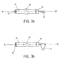
- the protrusion of the end portion 11 of the tubular heating element is obtained by stamping causing a flattening of the heating element with consequent enlargement, transverse to the stamping, as is clearly visible in the figures. 3a and 3b.
- the core 22 of the heating element 10 is also presented the core 22 of the heating element 10.
- This heating element is preferentially of the shielded type, that is to say consisting of a tube containing a resistive wire coil surrounded by magnesia.
- the loop 18 of the return means can slide to the connector 12 and can slide only between the protrusion 20 of the heating element and the side wall 4 of the cooking appliance. It is indeed not necessary to establish a fixed mechanical connection between these two elements, the return function can be performed with a relatively large latitude on the lever arm used.
- the end portions 11 of the heating element 10 may be inclined towards the return means so that the latter is located, by systematic sliding, against the outgrowth of the element heating.
- the biasing means 16 exerts its force in the same place, producing an identical torque during successive manipulations of the heating element 10 by the user. This feature ensures a reproducible and systematic positioning of the heating element in its working position and ensures the horizontality of said heating element.
- Another advantage to an angled disposition of the end portions is to prevent the sliding of the heating element 10 through the openings 8 when this heating element consists of only a single loop.
- the heating element can therefore be moved or pivoted to a position releasing the floor and / or the vault to facilitate cleaning, the pivot angle up to 90 °.
- the present invention may equally well be applied to a heating element located near the vault of the electrical apparatus or situated close to the sole of said apparatus, the possible inversion of the elastic return means 16 making it possible to adapt the mounting according to the position of the heating element.
- Another object of the invention relates to guiding and maintaining the heating element 10.
- the freedom given to the heating element to be able to pivot in order to disengage itself from its working position must, however, be limited in its movements. lateral, or in translation between the two side walls, by sliding in the opening 8 along the arrow G of Figure 4, or in rotation perpendicular to the allowed rotation, that is to say in a movement between the rear wall of the oven and the front door, according to the arrow F, figure 4.
- this principle of guidance and restriction of the deflections can be applied to any pivoting resistance, regardless of the presence or absence of a return means, therefore independently of the problem of the holding of the holding loop of the return means, and / or the location of the heating element in the furnace chamber, in the vaulted or in the sole position.
- the heating element when the heating element is in the sole position, it may not be provided with return means, the gravity being responsible for recalling the heating element in a horizontal position when it has been released from its working position.
- a protrusion such as the protrusion 20, judiciously positioned, then allows to avoid the deflections of the heating element.
- the protrusion 30 made on the end portions 11 of the heating element 10, close to the wall 4.
- the protrusion 30 can be obtained either by adding an element locally surrounding the heating element, either by deformation of the heating element, in particular by stamping.
- this lateral holding function of the heating element 10 can be combined with that of guiding or holding the loop 18 of the return means 16 by a judicious length of the end portions 11 of the heating element 10 so that the protrusion 30 is located substantially against the side wall 4.
- FIG. 4 illustrates this advantageous embodiment where the retaining loop 18 of the return means 16 is located between the protuberances 20 and 30.
- the loop 18 can slide on the end portion 11 between the two protrusions 20 and 30 which can be sufficiently close to each other. other to maintain, without play along the heating element, the holding loop 18, the protrusion 30 also avoiding the transverse movements of the heating element.
- a means for retaining the heating element when the latter is positioned, by lateral pivoting, out of from his working position may be simple hooks or metal clipping elements or any other similar device. The cleaning of the vault and / or the sole is then facilitated, the user does not have to hold the heating element in the retracted position to proceed with the cleaning.
- the electric cooking apparatus according to the present invention is advantageously an oven, a grill or a barbecue.
Landscapes
- Engineering & Computer Science (AREA)
- Chemical & Material Sciences (AREA)
- Combustion & Propulsion (AREA)
- Mechanical Engineering (AREA)
- General Engineering & Computer Science (AREA)
- Electric Stoves And Ranges (AREA)
- Baking, Grill, Roasting (AREA)
- Resistance Heating (AREA)
Claims (7)
- Elektrische Kochvorrichtung mit einem Rahmen (3), der wenigstens eine Unterhitzenwand und/oder eine Oberhitzenwand (5), wenigstens eine Seitenwand (4) aufweist, die einen Kochraum bilden, wenigstens einem rohrförmigen Heizelement (10), das in dem Kochraum in der Nachbarschaft der Oberhitze und/oder der Unterhitze der elektrischen Vorrichtung angeordnet ist, wobei das Heizelement (10) durch Drehung einerseits in eine horizontale Arbeitsposition und andererseits in eine Freisetzungsposition bezüglich der Arbeitsposition positioniert werden kann, dadurch gekennzeichnet, dass das Heizelement (10) zwei äußerste Teile (11) aufweist, deren freie Enden durch Verbinder (12) mit einer elektrischen Versorgungsschaltung für das Heizelement verbunden sind, wobei sich die äußersten Teile durch eine Öffnung (8) außerhalb des Kochraums erstrecken, die in einer der Seitenwände (4) vorgesehen ist und jeweils einen Vorsprung (30) aufweisen, der im wesentlichen an die Seitenwand (4) angrenzt, um die Ausschläge des Heizelements (10) durch Drehung und/oder durch Translation zu begrenzen.
- Elektrische Kochvorrichtung nach dem vorhergehenden Anspruch, dadurch gekennzeichnet, dass ein zweiter Vorsprung (20) an den äußersten Teilen (11) des Heizelements (10) gebildet ist, wobei der zweite Vorsprung mit einer Befestigung (18) zusammenwirken kann, die wenigstens teilweise das Heizelement (10) umgibt und am Ende eines Rückstellmittels (16) vorgesehen ist, das zwischen das Heizelement (10) und dem Rahmen (3) angeordnet ist und die Rückkehr des Heizelements aus seiner Freisetzungsposition in seine Arbeitsposition ermöglicht, wobei das Rückstellmittel (16) es ermöglicht, das Heizelement (10) in seiner Arbeitsstellung zu halten, wobei die Befestigung (18) des Rückstellmittels zwischen den gebildeten Vorsprüngen (20, 30) angeordnet ist.
- Elektrische Kochvorrichtung nach einem der vorhergehenden Ansprüche, dadurch gekennzeichnet, dass der an den äußersten Teilen (11) des Heizelements (10) gebildete Vorsprung oder wenigstens einer der daran gebildeten Vorsprünge durch Prägen des Heizelements (10) unter einer Presse erhalten ist.
- Elektrische Kochvorrichtung nach einem der Ansprüche 2 oder 3, dadurch gekennzeichnet, dass die äußersten Teile (11) des Heizelements (10) gebogen sind und eine zu dem Rückstellmittel (16) gerichtete Neigung aufweisen.
- Elektrische Kochvorrichtung nach einem der vorhergehenden Ansprüche, dadurch gekennzeichnet, dass der Rahmen (3) wenigstens ein Haltemittel aufweist, das dazu bestimmt ist, das Heizelement in einer aus seiner horizontalen Arbeitsposition freigesetzten Position zu halten.
- Elektrische Kochvorrichtung nach einem der vorhergehenden Ansprüche, dadurch gekennzeichnet, dass sie aus einem Elektroherd besteht.
- Elektrische Kochvorrichtung nach einem der Ansprüche 1 bis 5, dadurch gekennzeichnet, dass sie aus einem Grill besteht.
Applications Claiming Priority (3)
| Application Number | Priority Date | Filing Date | Title |
|---|---|---|---|
| FR9902258 | 1999-02-19 | ||
| FR9902258A FR2790066B1 (fr) | 1999-02-19 | 1999-02-19 | Element chauffant pivotant pour appareil electromenager de cuisson electrique |
| EP00420032A EP1030115B1 (de) | 1999-02-19 | 2000-02-16 | Schwenkbares Heizelement für elektrisches Gargerät |
Related Parent Applications (1)
| Application Number | Title | Priority Date | Filing Date |
|---|---|---|---|
| EP00420032A Division EP1030115B1 (de) | 1999-02-19 | 2000-02-16 | Schwenkbares Heizelement für elektrisches Gargerät |
Publications (3)
| Publication Number | Publication Date |
|---|---|
| EP1336802A2 EP1336802A2 (de) | 2003-08-20 |
| EP1336802A3 EP1336802A3 (de) | 2004-09-01 |
| EP1336802B1 true EP1336802B1 (de) | 2006-02-01 |
Family
ID=9542442
Family Applications (2)
| Application Number | Title | Priority Date | Filing Date |
|---|---|---|---|
| EP00420032A Expired - Lifetime EP1030115B1 (de) | 1999-02-19 | 2000-02-16 | Schwenkbares Heizelement für elektrisches Gargerät |
| EP03010549A Expired - Lifetime EP1336802B1 (de) | 1999-02-19 | 2000-02-16 | Schwenkbares Heizelement für elektrisches Gargerät |
Family Applications Before (1)
| Application Number | Title | Priority Date | Filing Date |
|---|---|---|---|
| EP00420032A Expired - Lifetime EP1030115B1 (de) | 1999-02-19 | 2000-02-16 | Schwenkbares Heizelement für elektrisches Gargerät |
Country Status (7)
| Country | Link |
|---|---|
| US (1) | US6184499B1 (de) |
| EP (2) | EP1030115B1 (de) |
| AT (2) | ATE317095T1 (de) |
| CA (1) | CA2299592A1 (de) |
| DE (2) | DE60025854T2 (de) |
| ES (2) | ES2258183T3 (de) |
| FR (1) | FR2790066B1 (de) |
Families Citing this family (4)
| Publication number | Priority date | Publication date | Assignee | Title |
|---|---|---|---|---|
| US7135288B2 (en) * | 2002-09-27 | 2006-11-14 | Ut-Battelle, Llc | Combinatorial synthesis of ceramic materials |
| US6917018B1 (en) * | 2002-11-22 | 2005-07-12 | Raymond Electric (China) Ltd. | Electric oven with reconfigurable heating elements |
| US8631739B2 (en) * | 2006-06-22 | 2014-01-21 | Kenyon International, Inc. | Grill |
| CN201318716Y (zh) * | 2008-11-11 | 2009-09-30 | 漳州灿坤实业有限公司 | 煎烤器的电热管组件 |
Family Cites Families (12)
| Publication number | Priority date | Publication date | Assignee | Title |
|---|---|---|---|---|
| US2918560A (en) * | 1956-08-10 | 1959-12-22 | Ferro Corp | Combination oven and heating unit |
| US3171947A (en) * | 1960-01-21 | 1965-03-02 | Wiegand Co Edwin L | Electric heater assemblies |
| US3076886A (en) * | 1960-10-10 | 1963-02-05 | Still Man Mfg Corp | Hinged electrical heater for oven top |
| US3024346A (en) * | 1960-12-27 | 1962-03-06 | Gen Electric | Oven heating unit support |
| US3197615A (en) * | 1961-03-20 | 1965-07-27 | Wiegand Co Edwin L | Electric heating apparatus |
| US3221140A (en) * | 1962-02-09 | 1965-11-30 | Ferro Corp | Hinged mounting for electric heating element |
| US3334215A (en) * | 1963-10-04 | 1967-08-01 | Gen Motors Corp | Domestic electrical appliance |
| US3296417A (en) * | 1964-07-31 | 1967-01-03 | Gen Electric | Hinging means for oven heating element |
| US3253811A (en) * | 1965-01-22 | 1966-05-31 | Ferro Corp | Support for sheathed electrical heating element |
| DE9405786U1 (de) * | 1994-04-07 | 1995-08-03 | AEG Hausgeräte GmbH, 90429 Nürnberg | Back- und Bratofenmuffel mit einem schwenkbaren Mantelrohr-Strahlungsheizkörper |
| FR2720917B1 (fr) | 1994-06-08 | 1996-07-26 | Seb Sa | Elément chauffant mobile pour appareil électrique de cuisson. |
| FR2752918B1 (fr) | 1996-08-29 | 2000-03-17 | Moulinex Sa | Four electrique de cuisson a resistance pivotante et procede de montage d'une resistance dans un tel four |
-
1999
- 1999-02-19 FR FR9902258A patent/FR2790066B1/fr not_active Expired - Fee Related
-
2000
- 2000-02-16 EP EP00420032A patent/EP1030115B1/de not_active Expired - Lifetime
- 2000-02-16 DE DE60025854T patent/DE60025854T2/de not_active Expired - Fee Related
- 2000-02-16 ES ES03010549T patent/ES2258183T3/es not_active Expired - Lifetime
- 2000-02-16 AT AT03010549T patent/ATE317095T1/de not_active IP Right Cessation
- 2000-02-16 ES ES00420032T patent/ES2204475T3/es not_active Expired - Lifetime
- 2000-02-16 DE DE60004716T patent/DE60004716T2/de not_active Expired - Lifetime
- 2000-02-16 AT AT00420032T patent/ATE248325T1/de not_active IP Right Cessation
- 2000-02-16 EP EP03010549A patent/EP1336802B1/de not_active Expired - Lifetime
- 2000-02-17 CA CA002299592A patent/CA2299592A1/fr not_active Abandoned
- 2000-02-22 US US09/510,224 patent/US6184499B1/en not_active Expired - Fee Related
Also Published As
| Publication number | Publication date |
|---|---|
| ATE317095T1 (de) | 2006-02-15 |
| ATE248325T1 (de) | 2003-09-15 |
| CA2299592A1 (fr) | 2000-08-19 |
| EP1030115B1 (de) | 2003-08-27 |
| EP1030115A1 (de) | 2000-08-23 |
| US6184499B1 (en) | 2001-02-06 |
| FR2790066A1 (fr) | 2000-08-25 |
| FR2790066B1 (fr) | 2001-04-06 |
| EP1336802A3 (de) | 2004-09-01 |
| DE60025854T2 (de) | 2006-08-10 |
| EP1336802A2 (de) | 2003-08-20 |
| ES2204475T3 (es) | 2004-05-01 |
| ES2258183T3 (es) | 2006-08-16 |
| DE60004716T2 (de) | 2004-07-01 |
| DE60025854D1 (de) | 2006-04-13 |
| DE60004716D1 (de) | 2003-10-02 |
Similar Documents
| Publication | Publication Date | Title |
|---|---|---|
| EP0617909B1 (de) | Elektrisches Gargerät | |
| EP0275785B1 (de) | Kombinierter elektrischer Backofen und Brotröster | |
| EP1525833B1 (de) | Brotroster | |
| FR2766977A1 (fr) | Dispositif de connexion pour appareil portatif | |
| FR2816454A1 (fr) | Bloc pour connexion de bornes de conducteurs | |
| EP1215983B1 (de) | Toastgerät mit einer erhitzungsvorrichtung für brötchen oder gleichartige nahrungsmittel | |
| EP1336802B1 (de) | Schwenkbares Heizelement für elektrisches Gargerät | |
| FR2772254A1 (fr) | Appareil de chauffage d'aliments | |
| EP1030114B1 (de) | Herausnehmbare Heizbaugruppe für Elektroherd | |
| FR2759889A1 (fr) | Grille-pain a positionnements multiples pour le chariot porte-pain | |
| FR2950239A1 (fr) | Grille-pain a porte laterale pivotante | |
| CA1057346A (fr) | Gril electrique perfectionne | |
| EP1941819B1 (de) | Kochgerät | |
| FR2599477A1 (fr) | Dispositif de cuisson electrique a haut rendement plus specialement destine a des restaurateurs ou a des collectives | |
| FR3117759A1 (fr) | Appareil de cuisson electrique pour la cuisson de produits alimentaires | |
| EP0686368B1 (de) | Bewegliches Heizelement für elektrisches Gargerät | |
| EP0845235B1 (de) | Toaster mit einem komplementären System zum Heben des Brotschlittens | |
| FR2948002A1 (fr) | Appareil electromenager, de type raclette, depliable | |
| EP1400193A1 (de) | Haube von einem elektrischen Waffeleisen | |
| FR2925148A1 (fr) | Systeme sortant telescopique | |
| EP0826928B1 (de) | Elektrischer Kochherd mit schwenkbarem Widerstand und ein Verfahren zur Befestigung des Widerstandes | |
| FR3030210A1 (fr) | Guide d'evacuation de vapeur sur un couvercle chauffant d'appareil de cuisson | |
| EP0262716A2 (de) | Vorrichtung zur Überwachung des Kochvorgangs von Gemüse | |
| FR3120774A1 (fr) | Pince pour produits alimentaires pourvue d’un dispositif de mesure d’épaisseur d’aliment | |
| EP4162848A1 (de) | Elektrischer feueranzünder |
Legal Events
| Date | Code | Title | Description |
|---|---|---|---|
| PUAI | Public reference made under article 153(3) epc to a published international application that has entered the european phase |
Free format text: ORIGINAL CODE: 0009012 |
|
| AC | Divisional application: reference to earlier application |
Ref document number: 1030115 Country of ref document: EP Kind code of ref document: P |
|
| AK | Designated contracting states |
Designated state(s): AT BE CH CY DE DK ES FI FR GB GR IE IT LI LU MC NL PT SE |
|
| PUAL | Search report despatched |
Free format text: ORIGINAL CODE: 0009013 |
|
| AK | Designated contracting states |
Kind code of ref document: A3 Designated state(s): AT BE CH CY DE DK ES FI FR GB GR IE IT LI LU MC NL PT SE |
|
| 17P | Request for examination filed |
Effective date: 20050207 |
|
| AKX | Designation fees paid |
Designated state(s): AT BE CH CY DE DK ES FI FR GB GR IE IT LI LU MC NL PT SE |
|
| GRAP | Despatch of communication of intention to grant a patent |
Free format text: ORIGINAL CODE: EPIDOSNIGR1 |
|
| GRAS | Grant fee paid |
Free format text: ORIGINAL CODE: EPIDOSNIGR3 |
|
| GRAC | Information related to communication of intention to grant a patent modified |
Free format text: ORIGINAL CODE: EPIDOSCIGR1 |
|
| GRAA | (expected) grant |
Free format text: ORIGINAL CODE: 0009210 |
|
| AC | Divisional application: reference to earlier application |
Ref document number: 1030115 Country of ref document: EP Kind code of ref document: P |
|
| AK | Designated contracting states |
Kind code of ref document: B1 Designated state(s): AT BE CH CY DE DK ES FI FR GB GR IE IT LI LU MC NL PT SE |
|
| PG25 | Lapsed in a contracting state [announced via postgrant information from national office to epo] |
Ref country code: FI Free format text: LAPSE BECAUSE OF FAILURE TO SUBMIT A TRANSLATION OF THE DESCRIPTION OR TO PAY THE FEE WITHIN THE PRESCRIBED TIME-LIMIT Effective date: 20060201 Ref country code: IE Free format text: LAPSE BECAUSE OF FAILURE TO SUBMIT A TRANSLATION OF THE DESCRIPTION OR TO PAY THE FEE WITHIN THE PRESCRIBED TIME-LIMIT Effective date: 20060201 Ref country code: AT Free format text: LAPSE BECAUSE OF FAILURE TO SUBMIT A TRANSLATION OF THE DESCRIPTION OR TO PAY THE FEE WITHIN THE PRESCRIBED TIME-LIMIT Effective date: 20060201 |
|
| REG | Reference to a national code |
Ref country code: GB Ref legal event code: FG4D Free format text: NOT ENGLISH |
|
| REG | Reference to a national code |
Ref country code: CH Ref legal event code: EP |
|
| PG25 | Lapsed in a contracting state [announced via postgrant information from national office to epo] |
Ref country code: MC Free format text: LAPSE BECAUSE OF NON-PAYMENT OF DUE FEES Effective date: 20060228 Ref country code: LI Free format text: LAPSE BECAUSE OF NON-PAYMENT OF DUE FEES Effective date: 20060228 Ref country code: CH Free format text: LAPSE BECAUSE OF NON-PAYMENT OF DUE FEES Effective date: 20060228 |
|
| REG | Reference to a national code |
Ref country code: IE Ref legal event code: FG4D Free format text: LANGUAGE OF EP DOCUMENT: FRENCH |
|
| REF | Corresponds to: |
Ref document number: 60025854 Country of ref document: DE Date of ref document: 20060413 Kind code of ref document: P |
|
| PG25 | Lapsed in a contracting state [announced via postgrant information from national office to epo] |
Ref country code: DK Free format text: LAPSE BECAUSE OF FAILURE TO SUBMIT A TRANSLATION OF THE DESCRIPTION OR TO PAY THE FEE WITHIN THE PRESCRIBED TIME-LIMIT Effective date: 20060501 Ref country code: SE Free format text: LAPSE BECAUSE OF FAILURE TO SUBMIT A TRANSLATION OF THE DESCRIPTION OR TO PAY THE FEE WITHIN THE PRESCRIBED TIME-LIMIT Effective date: 20060501 |
|
| GBT | Gb: translation of ep patent filed (gb section 77(6)(a)/1977) |
Effective date: 20060504 |
|
| PG25 | Lapsed in a contracting state [announced via postgrant information from national office to epo] |
Ref country code: PT Free format text: LAPSE BECAUSE OF FAILURE TO SUBMIT A TRANSLATION OF THE DESCRIPTION OR TO PAY THE FEE WITHIN THE PRESCRIBED TIME-LIMIT Effective date: 20060703 |
|
| REG | Reference to a national code |
Ref country code: ES Ref legal event code: FG2A Ref document number: 2258183 Country of ref document: ES Kind code of ref document: T3 |
|
| REG | Reference to a national code |
Ref country code: IE Ref legal event code: FD4D |
|
| REG | Reference to a national code |
Ref country code: CH Ref legal event code: PL |
|
| PLBE | No opposition filed within time limit |
Free format text: ORIGINAL CODE: 0009261 |
|
| STAA | Information on the status of an ep patent application or granted ep patent |
Free format text: STATUS: NO OPPOSITION FILED WITHIN TIME LIMIT |
|
| 26N | No opposition filed |
Effective date: 20061103 |
|
| PG25 | Lapsed in a contracting state [announced via postgrant information from national office to epo] |
Ref country code: GR Free format text: LAPSE BECAUSE OF FAILURE TO SUBMIT A TRANSLATION OF THE DESCRIPTION OR TO PAY THE FEE WITHIN THE PRESCRIBED TIME-LIMIT Effective date: 20060502 |
|
| PG25 | Lapsed in a contracting state [announced via postgrant information from national office to epo] |
Ref country code: LU Free format text: LAPSE BECAUSE OF NON-PAYMENT OF DUE FEES Effective date: 20060216 |
|
| PG25 | Lapsed in a contracting state [announced via postgrant information from national office to epo] |
Ref country code: CY Free format text: LAPSE BECAUSE OF FAILURE TO SUBMIT A TRANSLATION OF THE DESCRIPTION OR TO PAY THE FEE WITHIN THE PRESCRIBED TIME-LIMIT Effective date: 20060201 |
|
| PGFP | Annual fee paid to national office [announced via postgrant information from national office to epo] |
Ref country code: ES Payment date: 20090127 Year of fee payment: 10 |
|
| PGFP | Annual fee paid to national office [announced via postgrant information from national office to epo] |
Ref country code: NL Payment date: 20081125 Year of fee payment: 10 Ref country code: DE Payment date: 20090219 Year of fee payment: 10 |
|
| PGFP | Annual fee paid to national office [announced via postgrant information from national office to epo] |
Ref country code: GB Payment date: 20090211 Year of fee payment: 10 |
|
| PGFP | Annual fee paid to national office [announced via postgrant information from national office to epo] |
Ref country code: BE Payment date: 20090205 Year of fee payment: 10 |
|
| PGFP | Annual fee paid to national office [announced via postgrant information from national office to epo] |
Ref country code: IT Payment date: 20090227 Year of fee payment: 10 |
|
| BERE | Be: lapsed |
Owner name: S.A. *SEB Effective date: 20100228 |
|
| REG | Reference to a national code |
Ref country code: NL Ref legal event code: V1 Effective date: 20100901 |
|
| GBPC | Gb: european patent ceased through non-payment of renewal fee |
Effective date: 20100216 |
|
| PG25 | Lapsed in a contracting state [announced via postgrant information from national office to epo] |
Ref country code: NL Free format text: LAPSE BECAUSE OF NON-PAYMENT OF DUE FEES Effective date: 20100901 |
|
| PG25 | Lapsed in a contracting state [announced via postgrant information from national office to epo] |
Ref country code: DE Free format text: LAPSE BECAUSE OF NON-PAYMENT OF DUE FEES Effective date: 20100901 Ref country code: BE Free format text: LAPSE BECAUSE OF NON-PAYMENT OF DUE FEES Effective date: 20100228 |
|
| REG | Reference to a national code |
Ref country code: ES Ref legal event code: FD2A Effective date: 20110308 |
|
| PG25 | Lapsed in a contracting state [announced via postgrant information from national office to epo] |
Ref country code: GB Free format text: LAPSE BECAUSE OF NON-PAYMENT OF DUE FEES Effective date: 20100216 Ref country code: IT Free format text: LAPSE BECAUSE OF NON-PAYMENT OF DUE FEES Effective date: 20100216 |
|
| PG25 | Lapsed in a contracting state [announced via postgrant information from national office to epo] |
Ref country code: ES Free format text: LAPSE BECAUSE OF NON-PAYMENT OF DUE FEES Effective date: 20110307 |
|
| PG25 | Lapsed in a contracting state [announced via postgrant information from national office to epo] |
Ref country code: ES Free format text: LAPSE BECAUSE OF NON-PAYMENT OF DUE FEES Effective date: 20100217 |
|
| REG | Reference to a national code |
Ref country code: FR Ref legal event code: PLFP Year of fee payment: 17 |
|
| REG | Reference to a national code |
Ref country code: FR Ref legal event code: PLFP Year of fee payment: 18 |
|
| REG | Reference to a national code |
Ref country code: FR Ref legal event code: CA Effective date: 20170322 |
|
| REG | Reference to a national code |
Ref country code: FR Ref legal event code: PLFP Year of fee payment: 19 |
|
| PGFP | Annual fee paid to national office [announced via postgrant information from national office to epo] |
Ref country code: FR Payment date: 20190228 Year of fee payment: 20 |