EP1336809A2 - Wärmeaustauscher mit zweistufiger Wärmeübertragung - Google Patents
Wärmeaustauscher mit zweistufiger Wärmeübertragung Download PDFInfo
- Publication number
- EP1336809A2 EP1336809A2 EP02079400A EP02079400A EP1336809A2 EP 1336809 A2 EP1336809 A2 EP 1336809A2 EP 02079400 A EP02079400 A EP 02079400A EP 02079400 A EP02079400 A EP 02079400A EP 1336809 A2 EP1336809 A2 EP 1336809A2
- Authority
- EP
- European Patent Office
- Prior art keywords
- heat exchanger
- heat exchange
- shell
- exchange cavity
- end wall
- Prior art date
- Legal status (The legal status is an assumption and is not a legal conclusion. Google has not performed a legal analysis and makes no representation as to the accuracy of the status listed.)
- Withdrawn
Links
- 238000012546 transfer Methods 0.000 title claims description 37
- 239000012530 fluid Substances 0.000 claims abstract description 44
- 239000011257 shell material Substances 0.000 description 51
- XLYOFNOQVPJJNP-UHFFFAOYSA-N water Substances O XLYOFNOQVPJJNP-UHFFFAOYSA-N 0.000 description 41
- 238000013461 design Methods 0.000 description 16
- 238000010276 construction Methods 0.000 description 8
- RYGMFSIKBFXOCR-UHFFFAOYSA-N Copper Chemical compound [Cu] RYGMFSIKBFXOCR-UHFFFAOYSA-N 0.000 description 7
- 229910052802 copper Inorganic materials 0.000 description 7
- 239000010949 copper Substances 0.000 description 7
- 238000010438 heat treatment Methods 0.000 description 5
- 229910052751 metal Inorganic materials 0.000 description 5
- 239000002184 metal Substances 0.000 description 5
- 230000009182 swimming Effects 0.000 description 5
- 229910045601 alloy Inorganic materials 0.000 description 4
- 239000000956 alloy Substances 0.000 description 4
- 230000003750 conditioning effect Effects 0.000 description 4
- 239000010936 titanium Substances 0.000 description 4
- 229910052719 titanium Inorganic materials 0.000 description 4
- 229910000570 Cupronickel Inorganic materials 0.000 description 3
- RTAQQCXQSZGOHL-UHFFFAOYSA-N Titanium Chemical compound [Ti] RTAQQCXQSZGOHL-UHFFFAOYSA-N 0.000 description 3
- YOCUPQPZWBBYIX-UHFFFAOYSA-N copper nickel Chemical compound [Ni].[Cu] YOCUPQPZWBBYIX-UHFFFAOYSA-N 0.000 description 3
- 230000008901 benefit Effects 0.000 description 2
- 230000002349 favourable effect Effects 0.000 description 2
- 239000013529 heat transfer fluid Substances 0.000 description 2
- 239000003507 refrigerant Substances 0.000 description 2
- 150000003839 salts Chemical class 0.000 description 2
- 231100000331 toxic Toxicity 0.000 description 2
- 230000002588 toxic effect Effects 0.000 description 2
- 238000007792 addition Methods 0.000 description 1
- 238000004891 communication Methods 0.000 description 1
- 230000002860 competitive effect Effects 0.000 description 1
- 230000001143 conditioned effect Effects 0.000 description 1
- 239000007789 gas Substances 0.000 description 1
- 229930195733 hydrocarbon Natural products 0.000 description 1
- 150000002430 hydrocarbons Chemical class 0.000 description 1
- 238000009434 installation Methods 0.000 description 1
- 239000007788 liquid Substances 0.000 description 1
- 238000012423 maintenance Methods 0.000 description 1
- 238000004519 manufacturing process Methods 0.000 description 1
- 239000000463 material Substances 0.000 description 1
- 239000007769 metal material Substances 0.000 description 1
- 150000002739 metals Chemical class 0.000 description 1
- 238000000034 method Methods 0.000 description 1
- 238000012986 modification Methods 0.000 description 1
- 230000004048 modification Effects 0.000 description 1
- 238000012544 monitoring process Methods 0.000 description 1
- 230000037361 pathway Effects 0.000 description 1
- 230000008569 process Effects 0.000 description 1
- 230000002035 prolonged effect Effects 0.000 description 1
- -1 titanium metals Chemical class 0.000 description 1
Images


Classifications
-
- F—MECHANICAL ENGINEERING; LIGHTING; HEATING; WEAPONS; BLASTING
- F28—HEAT EXCHANGE IN GENERAL
- F28D—HEAT-EXCHANGE APPARATUS, NOT PROVIDED FOR IN ANOTHER SUBCLASS, IN WHICH THE HEAT-EXCHANGE MEDIA DO NOT COME INTO DIRECT CONTACT
- F28D7/00—Heat-exchange apparatus having stationary tubular conduit assemblies for both heat-exchange media, the media being in contact with different sides of a conduit wall
- F28D7/02—Heat-exchange apparatus having stationary tubular conduit assemblies for both heat-exchange media, the media being in contact with different sides of a conduit wall the conduits being helically coiled
- F28D7/024—Heat-exchange apparatus having stationary tubular conduit assemblies for both heat-exchange media, the media being in contact with different sides of a conduit wall the conduits being helically coiled the conduits of only one medium being helically coiled tubes, the coils having a cylindrical configuration
-
- F—MECHANICAL ENGINEERING; LIGHTING; HEATING; WEAPONS; BLASTING
- F28—HEAT EXCHANGE IN GENERAL
- F28F—DETAILS OF HEAT-EXCHANGE AND HEAT-TRANSFER APPARATUS, OF GENERAL APPLICATION
- F28F9/00—Casings; Header boxes; Auxiliary supports for elements; Auxiliary members within casings
- F28F9/22—Arrangements for directing heat-exchange media into successive compartments, e.g. arrangements of guide plates
- F28F2009/222—Particular guide plates, baffles or deflectors, e.g. having particular orientation relative to an elongated casing or conduit
- F28F2009/224—Longitudinal partitions
Definitions
- the present invention relates to a heat exchanger for thermal conditioning of one fluid medium by heat transfer with a second fluid medium in a heat transfer tube and, more particularly, to a heat exchanger construction to provide inner and outer flow spaces for a two stage heat transfer with a fluid medium also passed consecutively along the flow spaces.
- Evaporator and condenser functions provided by a heat exchanger are commonly used for diverse applications and while not so limited, the present invention is particularly useful in one common field of used where heat transfer with one medium consists of a flow of water for a swimming pool or spa.
- swimming pool water is heated or cooled depending on the climate affecting the temperature of the pool water.
- the present invention is particularly applicable to a heat exchanger using a tube-in-shell construction. It is known to heat a flow of water for a swimming pool in an elongated tank having an internal chamber in which an electrically resistive heating element, frequently as a coil, is housed. Water is directed in a lengthwise path through the tank chamber containing the heating element for transfer of heat from the heating element to the water.
- the heat transfer fluid is carried within a tube and the flow of water to be treated is directed past the tube, or tubes, within a shell housing.
- the heat exchanger consists of a tube within a tube and the fluids move either in the same direction, known as a "parallel flow” heat exchanger, or in opposite direction, known as a "counter flow” heat exchanger.
- the outer shell provides the outer boundary to the water passageway along the shell which is the only control over the flow of water once it has entered the shell.
- the heat exchange coils spaced inwardly from the sidewall of the shell enhances turbulence, thus also assisting in the desired heat transfer.
- Typical designs allow a large percentage of water entering the shell to pass through without coming in contact with the heat exchange coils.
- the tube in shell design typically uses plastic for the shell material and glued to construction prevents easy of disassembly for servicing of the heat exchanger.
- Such a construction although embodying a simple arrangement of parts, is costly as to fabrication.
- Patent no. 6,293,335 there is disclosed a tube and shell heat exchanger having a transversely oriented inlet port and a spirally coiled heat transfer tube contained within an arcuate chamber created by an internal baffle in which the water to be conditioned travels along a helical pathway in which the flow has minimized water depth and high turbulence.
- This water flow management design imposed a large water pressure drop along the path of travel along the arcuate chamber containing the heat transfer tube.
- the tube and shell heat exchanger maximizes heat transfer capability in a relatively easy to assemble design to make feasible the use of a higher cost material for the tubing such as titanium in a wide range of applications.
- the heat transfer tube is commonly formed from a metal such as copper or copper-nickel alloy to take advantage of favorable heat transfer properties and low cost of the metal material. Because of the favorable heat transfer properties with metals as copper and copper-nickel alloy, when heating an increased water flow is necessary the requirement is met by increasing the length of copper tubing in the coiled section thereby providing a greater residence time for the water flow in the heat exchanger. Where higher BTU heat transfer is needed for a given flow of water through the shell, providing a greater length of tubing to achieve the desired BTU heat transfer is conventional and cost effective rather than direct or otherwise manage the water flow to maximize heat transfer. Increasing the size of the heat exchanger to achieve the desired BTU heat transfer imposes a penalty of a disproportionate heat loss from the increase surface area of the housing needed to accommodate the additional length of tubing.
- a heat exchanger to thermally condition a fluid medium
- the heat exchanger including the combination of a shell having an outer shell sidewall spaced from an internal shell sidewall both closed in a fluid tight manner by a first end wall for defining an outer heat exchange cavity and an inner heat exchange cavity, a second end wall joined with the outer shell sidewall in a fluid tight manner and spaced from the internal shell sidewall to form a fluid pervious flow space interconnecting the outer heat exchange cavity and the inner heat exchange cavity, shell conduits forming an inlet port and an outlet port for conducting a flow of a first fluid medium along each of the outer heat exchange cavity and the inner heat exchange cavity, an elongated tubular conduit permeating the shell in a fluid tight manner and having a tubular conduit portion traversing the internal shell sidewall between outer helical conduit convolutions resident in the outer heat exchange cavity and inner helical conduit convolutions resident in the inner heat exchange cavity for conducting a second fluid medium in a heat transfer relation with the first fluid medium, and a flow
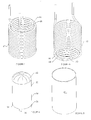
- FIG. 1 there is shown the preferred embodiment of a heat exchanger 10 embodying a construction and the arrangement of parts useful to form an evaporator unit or condenser unit for diverse applications including water heaters and water coolers particularly, for swimming pool water of swimming pools and spas.
- the heat exchanger includes an inverted bell jar shaped shell 12 defining a cylindrical outer shell sidewall 14 integral with an upper end wall 16 containing a centrally located fluid inlet port 18 through which a first fluid medium such as water is introduced into a supply header 20 ( Figure 3) of the heat exchanger.
- a fluid outlet port 22 is located radially outwardly in a shell sidewall enlargement 24 forming a discharge header 26 at the top of the shell from which the water exits the heat exchanger.
- the fluid inlet port 18 and fluid outlet port 22 contain threaded apertures for connection to piping forming part of the water flow circuit as a first fluid medium.
- the upper end wall 16 also contains angularly spaced apart access ports 24, 26 and 28 each provided with threads normally closed by a threaded plug or for receiving the internal threads of fittings used for mounting a thermal couple, a flow monitor and the like instruments to provide readouts of heater exchanger operating parameters at a remote monitoring site.
- the lower boundary to the shell 12 is formed with a radially extending flange 30 containing apertures 32 spaced about a bolt circle to receive stud members 34 extending from apertures formed in a bottom end wall 36 shown in detail in Figure 4.
- the stud members 34 have threads to receive nut members 38 to which sufficient torque is applied to form a sealed, fluid-tight connection between the cylindrical outer shell sidewall 14 and the bottom end wall 36.
- a seal 39 between the lower terminal edge of sidewall 14 and an annular seat surface 40 formed in the bottom end wall 36.
- the upper end wall 16 of the shell 12 is preferably provided with apertures of 41 spaced about the same bolt circle as apertures 32 so that elongated stud members may extend from the apertures from the bottom end wall 36 along the entire shell sidewall 14 where threaded end portions of the studs are fitted with nut members for securing the shell 12 to the bottom end wall 36 is a fluid type manner.
- the volume enclosed by the shell 12 and the bottom wall 36 contains a cylindrically shaped internal shell sidewall 42, shown in detail in Figure 5, supported at the upper end in a fluid type manner in an annular grove in the upper end wall 16 for defining an outer heat exchange cavity 44 as an elongated annulus between the cylindrical outer shell side wall 14 and in the internal shell sidewall 42.
- Inside the internal shell side wall 42 there is formed an inner heat exchange cavity 46 interconnected by a fluid pervious flow space 48 with the outer heat exchange cavity 44 formed by a gap separating the lower terminal edge of the internal sidewall 42 from the bottom end wall 36.
- a flow controller 50 has the form of a bell jar with a hemispherical dome 52 forming a lower boundary to the supply header 20.
- a cylindrical sidewall 54 is spaced uniformly from the internal cylindrical surface of the internal sidewall 42 to define the inner heat exchange cavity 46 as an elongated annulus bounded by the internal sidewall 42 and the cylindrical sidewall 54.
- the flow controller is held in this position by arcuate support segments 56 secured in an annular grove 58 formed in the bottom end wall 36. Gaps separating adjacent ones of the support segments 56 allow a fluid flow communication with the interior of the flow controller 50.
- a drain line extends in the bottom end wall 36 between the area beneath the hemispherical dome of the flow controller 50 and the atmosphere by way of a port 60 in an external sidewall of the bottom end wall 36.
- An elongated tubular conduit 62 has an inlet and an outlet permeating the upper end wall 16 of the shell 12 in a fluid tight manner by the use of suitable fittings 64.
- the tubular conduit 62 is made up of outer helical conduit convolutions 66 resident in the outer heat exchange cavity 44 and inner helical conduit convolutions 68 resident said inner heat exchange cavity 46 for conducting a second fluid medium in a heat transfer relation with the first fluid medium circulated through the cavities.
- the convolutions 66 and 68 are joined by a connector sleeve 70 which traversing the internal shell sidewall 42.
- the tubular conduit 62 conducts a heat transfer fluid such as a compressible heat transfer medium, for example nonflammable gases and liquid fluorinated hydrocarbons used as refrigerants (sold under the trademark Freon) or a sensible heat transfer medium such as water, through the heat exchanger.
- a heat transfer fluid such as a compressible heat transfer medium, for example nonflammable gases and liquid fluorinated hydrocarbons used as refrigerants (sold under the trademark Freon) or a sensible heat transfer medium such as water, through the heat exchanger.
- the present invention prevents a large percentage of water entering the shell to pass through without coming in contact with the tubular conduit by the provision of the flow controller 50 which is preferably made of plastic and arranged so that the diameter of the hemispherical dome 52 and depending side wall 54 fills the space inside the inner helical conduit convolutions 68. This forces all water to flow over tubing in its path through the shell rather than passing through the space inside the helix.
- the internal side wall 42 takes the form of a sleeve that encapsulates the outer helical conduit convolutions 66 between the side wall 54 including the hemispherical dome 52 and the internal side wall 42 maintains long continued contact of the water with the tubular conduit 62 which also enhances turbulence thus assisting with the heat transfer process.
- the provision of the sleeve like construction of the internal sidewall 42 allows a configuration the tubular conduit 62 as a coil in a coil and maintains the controlled flow of water over each respective conduit convolutions.
- the internal shell sidewall 42 in the form of a sleeve also allows the maintaining of a counter flow configuration between the refrigerant flow and water flow within the coil in coil configuration.
- This counter flow design enhances heat transfer, which typically has been a design compromise in tube in shell design utilizing a coil in coil configuration.
- This water flow management design also accomplishes a low-pressure drop through the coil on the waterside.
- the overall design configuration of the heat exchanger according to the present invention achieves high efficient performance over a wide range of flow rates. For comparison purposes, in a 100,000 Btuh, tube in tube coil design, the water flow requirements would be approximately 22 gpm. Typical tube in shell designs would require 40 plus gpm to achieve the same level of performance.
- the heat exchanger design of the present invention will match performance of the tube in tube at the same low flow rates as well as handle the higher flow rate which the tube in tube coils will not without excessive pressure drop.
- the bolt together design of the heat exchanger allows ease of disassembly for service or maintenance.
- Typical tube in shell design using plastic for the shell material are glued together preventing convenient disassembly.
- the provision of built in drain ports assures for freeze protection during severe winter months.
- Two drain ports are provided to facilitate vertical or horizontal installation of the heat exchanger.
- the shell design incorporates two bolt together patterns which allows the overall height to vary as required per Btuh rating without producing a dedicated shell size per capacity rating.
Landscapes
- Engineering & Computer Science (AREA)
- Physics & Mathematics (AREA)
- Thermal Sciences (AREA)
- Mechanical Engineering (AREA)
- General Engineering & Computer Science (AREA)
- Heat-Exchange Devices With Radiators And Conduit Assemblies (AREA)
Applications Claiming Priority (2)
| Application Number | Priority Date | Filing Date | Title |
|---|---|---|---|
| US78022 | 2002-02-15 | ||
| US10/078,022 US6499534B1 (en) | 2002-02-15 | 2002-02-15 | Heat exchanger with two-stage heat transfer |
Publications (2)
| Publication Number | Publication Date |
|---|---|
| EP1336809A2 true EP1336809A2 (de) | 2003-08-20 |
| EP1336809A3 EP1336809A3 (de) | 2006-07-05 |
Family
ID=22141436
Family Applications (1)
| Application Number | Title | Priority Date | Filing Date |
|---|---|---|---|
| EP02079400A Withdrawn EP1336809A3 (de) | 2002-02-15 | 2002-10-22 | Wärmeaustauscher mit zweistufiger Wärmeübertragung |
Country Status (4)
| Country | Link |
|---|---|
| US (1) | US6499534B1 (de) |
| EP (1) | EP1336809A3 (de) |
| AU (1) | AU2002301009A1 (de) |
| NZ (1) | NZ521282A (de) |
Families Citing this family (33)
| Publication number | Priority date | Publication date | Assignee | Title |
|---|---|---|---|---|
| US20030209345A1 (en) * | 2002-05-07 | 2003-11-13 | Zweig Mark Alan | Tube-in-tube repairable heat exchanger with cross flow |
| US7010936B2 (en) * | 2002-09-24 | 2006-03-14 | Rini Technologies, Inc. | Method and apparatus for highly efficient compact vapor compression cooling |
| NZ523962A (en) * | 2003-01-31 | 2004-10-29 | Energy Saving Concepts Ltd | Heat exchanger with multiple turbulent flow paths |
| NZ535969A (en) * | 2004-10-15 | 2006-07-28 | Garth Kennedy Mcgregor | Wastewater heat recovery |
| NZ562961A (en) | 2005-04-07 | 2011-03-31 | Benjamin Paul Baker | Heat exchangers for cooling beverages, the exchanger having adjustable baffles to change the heat transfer characteristics |
| US7306029B2 (en) * | 2005-10-26 | 2007-12-11 | Westinghouse Savannah River Company Llc | Two part condenser for varying the rate of condensing and related method |
| US20080264617A1 (en) * | 2007-04-26 | 2008-10-30 | David Martin | Heat exchanger |
| US7971603B2 (en) * | 2007-01-26 | 2011-07-05 | Hayward Industries, Inc. | Header for a heat exchanger |
| US20080223561A1 (en) * | 2007-01-26 | 2008-09-18 | Hayward Industries, Inc. | Heat Exchangers and Headers Therefor |
| WO2008124475A1 (en) | 2007-04-03 | 2008-10-16 | Global Heating Solutions, Inc. | Spa having heat pump system |
| USD574938S1 (en) | 2007-04-26 | 2008-08-12 | Hayward Industries, Inc. | Heat exchanger |
| US20090038785A1 (en) * | 2007-08-06 | 2009-02-12 | Zagalsky Harry Y | Tubes for heat exchange |
| US20090294097A1 (en) * | 2008-05-27 | 2009-12-03 | Rini Technologies, Inc. | Method and Apparatus for Heating or Cooling |
| US11047381B2 (en) * | 2008-11-17 | 2021-06-29 | Rini Technologies, Inc. | Method and apparatus for orientation independent compression |
| EP2470841B1 (de) * | 2009-09-28 | 2014-06-18 | Carrier Corporation | Flüssigkeitsgekühlter wärmetauscher in einem dampfkompressions-kühlsystem |
| EP2542761A4 (de) | 2010-03-01 | 2014-10-15 | Bright Energy Storage Technologies Llp | Drehkompressor-expander-systeme sowie entsprechende verfahren zu ihrer herstellung und verwendung |
| US20120118335A1 (en) * | 2010-11-17 | 2012-05-17 | Dean Gillingham | Pressure wash system |
| CA2839949A1 (en) | 2011-06-28 | 2013-01-03 | Bright Energy Storage Technologies, Llp | Semi-isothermal compression engines with separate combustors and expanders, and associated systems and methods |
| RU2616728C2 (ru) * | 2011-12-22 | 2017-04-18 | Тетра Лаваль Холдингз Энд Файнэнс С.А. | Змеевиковый теплообменник |
| MY183553A (en) * | 2012-06-29 | 2021-02-26 | Waterco Ltd | Heat exchanger |
| RU2522633C1 (ru) * | 2013-01-09 | 2014-07-20 | Общество с ограниченной ответственностью Научно-производственное предприятие "Донские технологии" | Конденсатор влажно-паровой микротурбины |
| US9897385B2 (en) * | 2015-02-20 | 2018-02-20 | Therma-Stor LLC | Helical coil heating apparatus and method of operation |
| WO2017151612A1 (en) * | 2016-02-29 | 2017-09-08 | The Regents Of The University Of California | Thermal energy storage system |
| DE102016005838A1 (de) * | 2016-05-12 | 2017-11-16 | Linde Aktiengesellschaft | Gewickelter Wärmeübertrager mit Einbauten zwischen Hemd und letzter Rohrlage |
| IT201600077849A1 (it) * | 2016-07-25 | 2018-01-25 | Gruppo Cimbali Spa | Dispositivo per il riscaldamento di fluidi in continuo. |
| EP3305388A1 (de) * | 2016-10-06 | 2018-04-11 | Linde Aktiengesellschaft | Wasserbadverdampfer und verfahrenstechnische anlage |
| CN107588578A (zh) * | 2017-09-28 | 2018-01-16 | 青岛开拓隆海制冷配件有限公司 | 一种低温空气源热泵采暖机水侧换热器及其制造方法 |
| EP3757485B1 (de) * | 2018-02-24 | 2023-08-02 | Zhejiang Sanhua Intelligent Controls Co., Ltd. | Gas-flüssigkeitsabscheider |
| US11225807B2 (en) | 2018-07-25 | 2022-01-18 | Hayward Industries, Inc. | Compact universal gas pool heater and associated methods |
| JP7299084B2 (ja) * | 2019-07-03 | 2023-06-27 | 三菱ケミカルインフラテック株式会社 | 熱交換器、その製造方法及び熱交換装置 |
| CN112240389B (zh) * | 2019-07-17 | 2024-08-20 | 迪森(常州)能源装备有限公司 | 一种卧式真空压力罐 |
| US12110707B2 (en) | 2020-10-29 | 2024-10-08 | Hayward Industries, Inc. | Swimming pool/spa gas heater inlet mixer system and associated methods |
| CN114797736B (zh) * | 2022-04-07 | 2023-04-11 | 西安交通大学 | 一种具有梯级保温功能的管流式水热和溶剂热合成反应器 |
Citations (3)
| Publication number | Priority date | Publication date | Assignee | Title |
|---|---|---|---|---|
| US2596812A (en) * | 1949-03-02 | 1952-05-13 | Robertshaw Fulton Controls Co | Water heater control |
| US5213156A (en) * | 1989-12-27 | 1993-05-25 | Elge Ab | Heat exchanger and a method for its fabrication |
| US6293335B1 (en) | 1999-06-24 | 2001-09-25 | Aquacal, Inc. | Method and apparatus for optimizing heat transfer in a tube and shell heat exchanger |
Family Cites Families (13)
| Publication number | Priority date | Publication date | Assignee | Title |
|---|---|---|---|---|
| US1911464A (en) * | 1929-04-12 | 1933-05-30 | Swan A Pearson | Refrigerating system |
| FR2034754A6 (de) * | 1968-03-06 | 1970-12-18 | Mille Gaston | |
| US3526273A (en) * | 1968-07-31 | 1970-09-01 | Borg Warner | Heat exchanger |
| US4257479A (en) * | 1979-04-02 | 1981-03-24 | Sunburst Solar Energy Corp. | Heat exchanger and drain down for solar collector |
| FR2481787A1 (fr) * | 1979-11-09 | 1981-11-06 | Tech Thermiq Frigo Exploit | Unite mobile de traitement thermique des vins et autres fluides |
| DE8210810U1 (de) * | 1982-04-16 | 1982-08-12 | Anton Steinecker Maschinenfabrik Gmbh, 8050 Freising | Waermetauscher |
| NL192367C (nl) * | 1984-03-26 | 1997-07-04 | Braak Bv Geb | Suikerkooktoestel. |
| DE8712814U1 (de) * | 1987-09-23 | 1989-01-19 | VIA Gesellschaft für Verfahrenstechnik mbH, 4000 Düsseldorf | Meßgaskühleinrichtung |
| SE457330B (sv) * | 1987-10-20 | 1988-12-19 | Tilly S Roer Ab | Anordning foer temperering och homogenisering av troegflytande massor |
| US4907418A (en) * | 1988-11-14 | 1990-03-13 | Defazio Louis C | Liquid heating system particularly for use with swimming pools or the like |
| FR2660056B1 (fr) * | 1990-03-23 | 1994-07-22 | Muller Cie | Echangeur pour eau chaude sanitaire notamment pour chaudiere murale. |
| US5487423A (en) * | 1993-02-16 | 1996-01-30 | Piscine Service Anjou Sa | Heat exchanger |
| WO1999067584A1 (en) * | 1998-06-25 | 1999-12-29 | Energy Saving Concepts Limited | Heat exchanger tracking |
-
2002
- 2002-02-15 US US10/078,022 patent/US6499534B1/en not_active Expired - Fee Related
- 2002-09-10 NZ NZ521282A patent/NZ521282A/en unknown
- 2002-09-13 AU AU2002301009A patent/AU2002301009A1/en not_active Abandoned
- 2002-10-22 EP EP02079400A patent/EP1336809A3/de not_active Withdrawn
Patent Citations (3)
| Publication number | Priority date | Publication date | Assignee | Title |
|---|---|---|---|---|
| US2596812A (en) * | 1949-03-02 | 1952-05-13 | Robertshaw Fulton Controls Co | Water heater control |
| US5213156A (en) * | 1989-12-27 | 1993-05-25 | Elge Ab | Heat exchanger and a method for its fabrication |
| US6293335B1 (en) | 1999-06-24 | 2001-09-25 | Aquacal, Inc. | Method and apparatus for optimizing heat transfer in a tube and shell heat exchanger |
Also Published As
| Publication number | Publication date |
|---|---|
| NZ521282A (en) | 2004-06-25 |
| EP1336809A3 (de) | 2006-07-05 |
| AU2002301009A1 (en) | 2003-09-04 |
| US6499534B1 (en) | 2002-12-31 |
Similar Documents
| Publication | Publication Date | Title |
|---|---|---|
| US6499534B1 (en) | Heat exchanger with two-stage heat transfer | |
| US6293335B1 (en) | Method and apparatus for optimizing heat transfer in a tube and shell heat exchanger | |
| US4462463A (en) | Triple pass heat exchanger | |
| US20190212062A1 (en) | Helical coil-on-tube heat exchanger | |
| US8214936B2 (en) | Spa having heat pump system | |
| US6920917B2 (en) | Double-pipe heat exchanger | |
| US20060124285A1 (en) | Heat exchanger | |
| EP2844941B1 (de) | Wärmetauscher | |
| US4365483A (en) | Vertical convection heat dissipation tower | |
| US4989670A (en) | Heat exchanger | |
| CN104412059A (zh) | 热交换器 | |
| JP2016217669A (ja) | 二重管式熱交換器及びヒートポンプ式給湯装置 | |
| EP0957327A1 (de) | Wärmetauscher-Rohrschlange | |
| US20050139344A1 (en) | Internal water tank solar heat exchanger | |
| CN210321312U (zh) | 一种多管盘绕式换热器 | |
| US7055339B2 (en) | Integrated thermosyphon refrigerant heat recovery system and hot water heater | |
| US6668136B2 (en) | Integral heating and cooling unit | |
| CN219200145U (zh) | 一种板式换热器 | |
| WO2009008698A2 (en) | Heat exchanger | |
| EP0640200A1 (de) | Schneller waermetauscher | |
| RU202931U1 (ru) | Улучшенный теплообменник | |
| KR200218059Y1 (ko) | 스태틱 믹서의 엘러먼트를 이용한 다중관 열교환기 | |
| CN206930187U (zh) | 螺旋式热交换器 | |
| CN2341105Y (zh) | 螺旋盘管水-水换热器 | |
| CN112097420A (zh) | 壳管式换热器及其控制方法和热泵机组 |
Legal Events
| Date | Code | Title | Description |
|---|---|---|---|
| PUAI | Public reference made under article 153(3) epc to a published international application that has entered the european phase |
Free format text: ORIGINAL CODE: 0009012 |
|
| AK | Designated contracting states |
Designated state(s): AT BE BG CH CY CZ DE DK EE ES FI FR GB GR IE IT LI LU MC NL PT SE SK TR |
|
| AX | Request for extension of the european patent |
Extension state: AL LT LV MK RO SI |
|
| PUAL | Search report despatched |
Free format text: ORIGINAL CODE: 0009013 |
|
| AK | Designated contracting states |
Kind code of ref document: A3 Designated state(s): AT BE BG CH CY CZ DE DK EE ES FI FR GB GR IE IT LI LU MC NL PT SE SK TR |
|
| AX | Request for extension of the european patent |
Extension state: AL LT LV MK RO SI |
|
| AKX | Designation fees paid |
Designated state(s): DE ES FR GB PT |
|
| 17P | Request for examination filed |
Effective date: 20060216 |
|
| R17P | Request for examination filed (corrected) |
Effective date: 20061116 |
|
| 17Q | First examination report despatched |
Effective date: 20070219 |
|
| STAA | Information on the status of an ep patent application or granted ep patent |
Free format text: STATUS: THE APPLICATION IS DEEMED TO BE WITHDRAWN |
|
| 18D | Application deemed to be withdrawn |
Effective date: 20090505 |