EP1338190B1 - Dispositif de distribution pour des produits hachés issus d'une récolteuse - Google Patents
Dispositif de distribution pour des produits hachés issus d'une récolteuse Download PDFInfo
- Publication number
- EP1338190B1 EP1338190B1 EP03100222A EP03100222A EP1338190B1 EP 1338190 B1 EP1338190 B1 EP 1338190B1 EP 03100222 A EP03100222 A EP 03100222A EP 03100222 A EP03100222 A EP 03100222A EP 1338190 B1 EP1338190 B1 EP 1338190B1
- Authority
- EP
- European Patent Office
- Prior art keywords
- mode
- guide
- position input
- distributing device
- motor
- Prior art date
- Legal status (The legal status is an assumption and is not a legal conclusion. Google has not performed a legal analysis and makes no representation as to the accuracy of the status listed.)
- Expired - Lifetime
Links
- 239000010902 straw Substances 0.000 claims description 14
- 238000003306 harvesting Methods 0.000 claims description 8
- 239000000463 material Substances 0.000 claims description 8
- 239000004459 forage Substances 0.000 claims description 3
- 238000009826 distribution Methods 0.000 description 10
- 241001124569 Lycaenidae Species 0.000 description 5
- 230000008859 change Effects 0.000 description 3
- 238000005520 cutting process Methods 0.000 description 3
- 230000002441 reversible effect Effects 0.000 description 3
- 230000007704 transition Effects 0.000 description 3
- 230000006870 function Effects 0.000 description 2
- 238000003825 pressing Methods 0.000 description 2
- 230000004913 activation Effects 0.000 description 1
- 230000006978 adaptation Effects 0.000 description 1
- 238000004140 cleaning Methods 0.000 description 1
- 230000008878 coupling Effects 0.000 description 1
- 238000010168 coupling process Methods 0.000 description 1
- 238000005859 coupling reaction Methods 0.000 description 1
- 238000010586 diagram Methods 0.000 description 1
- 230000000694 effects Effects 0.000 description 1
- 239000012530 fluid Substances 0.000 description 1
- 238000000034 method Methods 0.000 description 1
- 239000010908 plant waste Substances 0.000 description 1
- 238000002360 preparation method Methods 0.000 description 1
- 230000008569 process Effects 0.000 description 1
- 230000002035 prolonged effect Effects 0.000 description 1
- 230000000717 retained effect Effects 0.000 description 1
- 238000000926 separation method Methods 0.000 description 1
- 239000002689 soil Substances 0.000 description 1
- 239000004575 stone Substances 0.000 description 1
- 238000003860 storage Methods 0.000 description 1
- 238000003971 tillage Methods 0.000 description 1
- 230000000007 visual effect Effects 0.000 description 1
- 238000011179 visual inspection Methods 0.000 description 1
Images


Classifications
-
- A—HUMAN NECESSITIES
- A01—AGRICULTURE; FORESTRY; ANIMAL HUSBANDRY; HUNTING; TRAPPING; FISHING
- A01F—PROCESSING OF HARVESTED PRODUCE; HAY OR STRAW PRESSES; DEVICES FOR STORING AGRICULTURAL OR HORTICULTURAL PRODUCE
- A01F12/00—Parts or details of threshing apparatus
- A01F12/40—Arrangements of straw crushers or cutters
-
- Y—GENERAL TAGGING OF NEW TECHNOLOGICAL DEVELOPMENTS; GENERAL TAGGING OF CROSS-SECTIONAL TECHNOLOGIES SPANNING OVER SEVERAL SECTIONS OF THE IPC; TECHNICAL SUBJECTS COVERED BY FORMER USPC CROSS-REFERENCE ART COLLECTIONS [XRACs] AND DIGESTS
- Y10—TECHNICAL SUBJECTS COVERED BY FORMER USPC
- Y10S—TECHNICAL SUBJECTS COVERED BY FORMER USPC CROSS-REFERENCE ART COLLECTIONS [XRACs] AND DIGESTS
- Y10S460/00—Crop threshing or separating
- Y10S460/901—Material distributor
Definitions
- the invention relates to a distribution device for emerging from a harvester chaff, with a guide for specifying the ejection of the chaff, a set up for adjusting the direction of ejection of the guide motor and a control device with the motor and at least one manually operable position input device for entering the position of the Leit Vietnamese is connected.
- the continuous adjustment of the baffles is omitted and the operator adjusts the baffles to a fairly small distribution width, in which no shredded material is thrown into the still standing stock.
- the result is that the shredded material is not ejected to full cutting width. This is particularly disadvantageous in minimally invasive soil cultivation (no tillage). If shredded material nevertheless reaches the standing stock, blockages of the mower often occur.
- a harvesting machine is described with a rotatable about the vertical axis chute for transferring chopped crops in a hold of a support vehicle. Information about the respective position of the discharge elbow is stored. Upon actuation of a corresponding button, the spout is rotated to the mirrored position relative to the longitudinal axis of the harvester to position the escort vehicle at the same position of the harvester after being turned over at the edge of the field.
- Applicant's CTS combine harvesters use a multi-button drive lever. Some buttons are used to recall pre-programmed treble and forward / reverse positions of the reel. If a key is pressed briefly, the stored values are recalled. If it is pressed longer, a later retrievable information about the current position of the reel is stored.
- the object underlying the invention is seen to provide a little expensive, but user-friendly device for adjusting the vanes.
- the invention proposes that the control device at least in a first and a second selectable mode is operable.
- the first mode is selected by operating the operator-operable position input means only relatively briefly, ie, for a period of time that is below a predetermined threshold.
- the controller causes the engine to spill the nozzle to a predetermined position.
- the second mode is selected by operating the same position input device by operating for a longer period of time that is above the threshold.
- the controller causes the motor to move the guide as long as the position input device is actuated.
- the engine spends the nozzle to a predetermined position.
- This position may be a position corresponding to position information stored in a memory. The operator can then retrieve the desired position by selecting the first mode. If several position input devices are present, several positions are available. In many cases, for example, after a change of direction, however, it makes sense to spend the guide in a position which is symmetrical to the previous position of the guide with respect to the longitudinal center plane of the harvester.
- the baffles of the baffle are initially pivoted to the left, for example, by 20 ° with respect to the longitudinal axis to prevent crop residue from entering the stock on the right side of the harvester, the baffle will reverse after turning at the field end upon activation of the first mode Pivoted 40 ° to the right, so that it is located 20 ° to the right with respect to the longitudinal center plane, because then the stock is on the left side of the harvester. But it can also be approached the last set value beyond the longitudinal axis, so that unbalanced positions can be approached. The latter may be useful, for example, in crosswinds, since then in the first direction of the guide less far (or further) must be adjusted as in the other direction.
- the predetermined threshold value for the first period of time, after which the control device transitions into the second operating mode, is preferably changeable. It can be entered, for example via a keyboard in an on-board computer of the harvester.
- the control device goes into a third mode after the second mode has been left, that is, the position input device is no longer actuated.
- the third mode upon actuation of the position input device, bypassing the first mode leading to an undesired adjustment of the guide in this case, the second mode is immediately called, in which the guide is moved as long as the position input device is actuated.
- the third mode is active for a predetermined (second) period of time, the amount of which is preferably variable, in particular by means of a keyboard. If two position input devices are present, to which opposite adjustment directions of the guide are assigned, the third mode is activated after completion of the second mode expediently for both position input devices, so that then a fine adjustment of the guide by operating the two position input devices in both directions is possible.
- the invention can be used on combines, in which the guide is arranged downstream of a straw chopper. It is also suitable for forage harvesters, the guide is a downstream of a chopper drum arranged chute.
- the guide may be known baffles, which are arranged downstream of a straw chopper and attached to a straw distribution hood.
- the guide may also be a shaft downstream of a fan.
- the shaft may also be arranged downstream of a chopper, for example a disc wheel chopper.
- Such a shaft can be continuously around an approximately vertical Axis pivoted back and forth to cover a sufficient width, which preferably corresponds approximately to the cutting width.
- the invention makes it possible to adjust the range of movement of the shaft automatically to enter limits.
- such a chopper equipped with a chute for ejecting the chopped material may be moved from the operating position in which straw is ejected to an inoperative position where the chaff ejected by the cleaning device is ejected through the chopper and the chute.
- the shaft located in the inoperative position is spent by the control device and the engine in an enterable position. This embodiment is particularly useful if only a single shredder with only one slot is available.
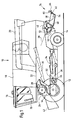
- a harvester 10 in the form of a self-propelled combine harvester shown in Figure 1 is supported on front driven and rear steerable wheels 12 and 14, respectively, and has a driver's cab 16 from which it can be operated by a driver.
- the driver's cab 16 is closed at the rear Grain tank 18, which can deliver discharged through a drain pipe 20 to the outside.
- the grain tank 18 rests on a frame 22, in the supplied good on the way via a threshing drum 24, a concave 26 and a beater 28 is decomposed into its large and small components.
- the straw chopper 40 comprises a rotor 46 with pendulum-hung flails 48 distributed around its circumference and along its length and rotating in a housing 50 about an approximately horizontal axis transverse to the direction of travel. In cooperation with counter knives 52, the threshed, large Erntegutmaschine crushed to shredded.
- a distribution device 54 shown in more detail in Figure 2 is arranged, which comprises a number of laterally juxtaposed vanes 56 in the form of straw guide plates, which are arranged below a straw distributor hood 58.
- the at its front in the direction of travel in the direction of travel about a vertical axis 66 pivotally mounted on the straw cover 58 guide devices 56 are coupled in their direction of travel further back area by a slide 62 with each other, which extends through a through a slot in the straw distributor cap 58 upwards
- Coupling rod 64 is connected to a motor 60 in the form of a double-acting hydraulic cylinder with a piston rod 68.
- motor 60 is set up to adjust the rear ends of the guide devices 56 transversely to the direction of travel and to specify the direction of ejection of the guide devices 56 where the shredded material flows past. Furthermore, it is conceivable that each of the left and right half of the baffles are each adjustable by a separate motor.
- the motor 60 is connectable by a valve assembly 70 to a source 74 of pressurized hydraulic fluid.
- the valve assembly 70 is electromagnetically controlled by an electronic controller 72.
- a mechanically coupled to the slider 62 sensor 86 which may be implemented as a slide potentiometer, for example, is connected to the control device 72 to supply it for feedback purposes, a signal containing information about the position of the slider 62.
- a driving lever 76 is arranged next to a driver's seat. It is pivotable about a horizontal axis extending transversely to the direction of travel and serves to specify the forwarding speed of the harvesting machine 10 in one field.
- the driving lever 76 On its upper side, the driving lever 76 is provided with a head 78 on which a series of pushable buttons are arranged. Two of the keys serve as position input devices 80, 82.
- the right position input device 80 is labeled with an R and serves to adjust the vanes 56 to the right.
- the left position input device 82 is labeled with an L and is used to adjust the vanes 56 to the left. Other buttons control other functions of the harvester.
- the position input devices 80, 82 are connected to the control device 72 via a line, in particular via a bus line. It would also be conceivable to arrange the position input devices 80, 82 at any other location in the driver's cab 16.
- the controller 72 is further connected to a non-volatile, battery-backed storage device 84.
- controller 72 sequentially performs the routines shown in Figs. 3 and 4 at relatively short intervals (a few milliseconds).
- step 102 a query is made as to whether the position input device 82 (ie, the key labeled L) is pressed. If this is not the case, the routine is ended in step 104. Otherwise, step 104 follows, in which it is queried whether a time has elapsed since the last adjustment of the guide (step 106 or step 206) which is greater than a predetermined time period T2. If this time duration, which may be 10 seconds, for example, has not yet expired, the control device 72 is in a third operating mode, in which the actuation of the position input device 82 immediately an adjustment of the guide 54 in the direction of the position input device 82 associated direction, ie to the left , entails.
- step 106 follows, in which the motor 60 is activated and the guide 54 is moved to the left.
- step 106 is followed by step 108, in which it is queried whether the position input device 82 has been released by the operator. If not, step 106 follows again. If this is the case, step 109 follows, in which it is queried whether the guide 54 is located to the right of the center. If this is the case, step 110 follows, in which an information derived from the measured value of the sensor 86 about the respective position of the guide 54 on the right side is stored in the memory device 84 and to which the routine is ended in step 104.
- step 111 follows, in which information about the respective position derived from the measured value of the sensor 86 is obtained of the guide 54 on the left side is stored in the memory device 84, and the routine is terminated in step 104. It is thus possible depending on the controlled position of the guide 54 to store position data for the left and right side, which facilitates an asymmetrical driving. If the baffle 54 is initially right and is slightly displaced to the left, it remains on the right. Your position information is then stored in step 110 as the right position. But if it is moved beyond the center to the left, it is stored in step 111 as the left position. When the keys 80 and 82 are subsequently pressed, the information assigned to the positions left or right is retrieved.
- step 104 shows that since the last adjustment of the guide 54 in step 106, a time has elapsed which is greater than the time period T2, the control device can switch to the first or second operating mode.
- step 104 is then followed by step 112, in which a predetermined period T1 (eg, 2 seconds) is awaited.
- step 114 in which it is queried whether the position input device 82 has since been released. If so, the position input device 82 has thus been actuated for a relatively short time only, step 116 is followed by the control device 72 inquiring whether the guide 54 is to the right of the center.
- step 104 follows, otherwise step 118, in which the control device 72 transitions into the first operating mode and causes the motor 60 to store the guide device 54 in a position which corresponds to the last stored value on the left side. It would also be conceivable for the guide device to be brought into the position which is symmetrical with respect to the longitudinal center plane of the harvesting machine 10 to the position corresponding to the information stored in the memory device 84. In this case, the signals of the sensor 86 and the information from the memory device 84 are used.
- step 116 is skipped if the guide is already on the left, possibly accompanied by an acoustic and / or visual error message. In this case, the operator would have to briefly operate the other position input device 80 to pivot the guide 56 to the right side.
- step 106 again follows.
- the control device thus transitions into the second operating mode, in which the position input device 80 causes the guide device 54 to be moved to the left.
- the routine shown in FIG. 4 essentially corresponds to that shown in FIG. 3; however, it is interrogated in each case whether the position input device 80 marked with R has been actuated, and in step 206 the guide device 54 is rotated to the right. It should be noted that in steps 104 and 204, the time that has elapsed since any movement of the guide 54, d. H. regardless of whether it has been moved to the left in step 106 or to the right in step 206. In addition, appropriate measures must be taken if both position input devices 80, 82 are actuated exactly at the same time.
- the distribution device 54 allows the guide 56 to be adjusted with the same position input devices 80 and 82 in different selectable modes.
- first by briefly pressing one of the position input devices 80, 82 activatable mode (step 116 and 216) is in each case the last approached on the other side of the longitudinal center plane (or the current position to the longitudinal center plane symmetrical) approached.
- This mode allows for a change of direction easy adaptation of the guide 56 to the new conditions.
- second mode of operation selectable over a period of time longer than T1
- the guide 56 is moved as long as the position input device 80, 82 is actuated, and an adjustment range may be set at which End of the motor 60 is automatically switched off.
- the third operating mode comes into force, in which, for a period of time T2, an actuation of the position input device leads immediately to the second operating mode.
Landscapes
- Life Sciences & Earth Sciences (AREA)
- Environmental Sciences (AREA)
- Harvester Elements (AREA)
- Combines (AREA)
- Arrangement And Mounting Of Devices That Control Transmission Of Motive Force (AREA)
- Hybrid Electric Vehicles (AREA)
- Table Equipment (AREA)
Claims (10)
- Dispositif de distribution (54) de produits hachés sortant d'une machine de récolte (10), comportant un dispositif de guidage (56), destiné à définir la direction d'éjection des produits hachés, un moteur (60), conçu pour régler la direction d'éjection du dispositif de guidage (56), et un dispositif de commande (72), qui est relié au moteur (60), ainsi qu'à au moins un dispositif d'entrée de position (80, 82), apte à être actionné par la personne de service et prévu pour entrer la position du dispositif de guidage (56), caractérisé en ce que le dispositif de commande (72) peut être activé au choix dans un premier mode de service et dans un deuxième mode de service, le premier mode de service étant activé lors d'un actionnement du dispositif d'entrée de position (80, 82) pour un laps de temps qui est inférieur à une valeur seuil prédéfinie, et le deuxième mode de service étant activé lors d'un actionnement du dispositif d'entrée de position (80, 82) pour un laps de temps qui est supérieur à une valeur seuil prédéfinie, et en ce que le dispositif de commande (72) active le moteur (60) dans le premier mode de service de telle sorte que le dispositif de guidage (56) est amené dans une position prédéfinie, et active le moteur (60) dans le deuxième mode de service tant que le dispositif d'entrée de position (78) est actionné.
- Dispositif de distribution selon la revendication 1, caractérisé en ce que deux dispositifs d'entrée de position (80, 82) sont présents, auxquels sont associées des directions de mouvement opposées du dispositif de guidage (56).
- Dispositif de distribution selon la revendication 1 ou 2, caractérisé en ce que le dispositif de commande (72) active le moteur (60) dans le premier mode de service de telle sorte que le dispositif de guidage (56) est amené dans une position symétrique à sa position actuelle par rapport à l'axe longitudinal de la machine de récolte (10) ou dans la position activée en dernier lieu sur le côté opposé.
- Dispositif de distribution (54) selon l'une quelconque des revendications précédentes, caractérisé en ce que le dispositif de commande (72), à la fin du deuxième mode de service et/ou avant l'entrée dans le premier mode de service, enregistre en mémoire une information sur la position respective du dispositif de guidage (56).
- Dispositif de distribution (54) selon l'une quelconque des revendications précédentes, caractérisé en ce que la valeur seuil prédéfinie pour le laps de temps est modifiable, en particulier par introduction.
- Dispositif de distribution (54) selon l'une quelconque des revendications précédentes, caractérisé en ce que le dispositif de commande (72), à la sortie du deuxième mode de service, passe dans un troisième mode de service pour un deuxième laps de temps prédéfini, dans lequel le deuxième mode de service est activé immédiatement après l'actionnement du dispositif d'entrée de position (78).
- Dispositif de distribution (54) selon la revendication 6, caractérisé en ce que la durée du deuxième laps de temps est modifiable, en particulier par introduction.
- Dispositif de distribution (54) selon l'une quelconque des revendications précédentes, caractérisé en ce que le dispositif de guidage (56) est monté en aval d'un hache-paille (40).
- Dispositif de distribution (54) selon l'une quelconque des revendications précédentes, caractérisé en ce que le dispositif de guidage (56) est formé par une ou plusieurs tôles déflectrices.
- Machine de récolte (10), en particulier moissonneuse-batteuse ou ensileuse, comportant un dispositif de distribution (54) selon l'une quelconque des revendications précédentes.
Applications Claiming Priority (2)
| Application Number | Priority Date | Filing Date | Title |
|---|---|---|---|
| DE10207479A DE10207479A1 (de) | 2002-02-22 | 2002-02-22 | Verteilvorrichtung für aus einer Erntemaschine austretendes Häckselgut |
| DE10207479 | 2002-02-22 |
Publications (2)
| Publication Number | Publication Date |
|---|---|
| EP1338190A1 EP1338190A1 (fr) | 2003-08-27 |
| EP1338190B1 true EP1338190B1 (fr) | 2007-02-21 |
Family
ID=27635232
Family Applications (1)
| Application Number | Title | Priority Date | Filing Date |
|---|---|---|---|
| EP03100222A Expired - Lifetime EP1338190B1 (fr) | 2002-02-22 | 2003-02-04 | Dispositif de distribution pour des produits hachés issus d'une récolteuse |
Country Status (6)
| Country | Link |
|---|---|
| US (1) | US6729953B2 (fr) |
| EP (1) | EP1338190B1 (fr) |
| AR (1) | AR038573A1 (fr) |
| BR (1) | BR0300390A (fr) |
| CA (1) | CA2418867C (fr) |
| DE (2) | DE10207479A1 (fr) |
Families Citing this family (21)
| Publication number | Priority date | Publication date | Assignee | Title |
|---|---|---|---|---|
| GB0214086D0 (en) * | 2002-06-19 | 2002-07-31 | Cnh Belgium Nv | Crop chopper arrangements for agricultural machinery |
| DE10342922A1 (de) * | 2003-09-15 | 2005-05-19 | Claas Selbstfahrende Erntemaschinen Gmbh | Häcksel- und Verteilvorrichtung |
| US7306174B2 (en) * | 2004-03-04 | 2007-12-11 | Deere & Company | Broadcast width and location control for a combine spreader |
| CA2465142C (fr) | 2004-04-23 | 2009-06-02 | Redekop Chaff Systems Ltd. | Moissonneuse-batteuse avec dispositif de projection muni d'une commande independante de largeur d'etalement |
| US6939221B1 (en) * | 2004-04-26 | 2005-09-06 | Redekop Chaff Systems Ltd. | Combine harvester with a spreader having independent spread width control |
| EP1671530B1 (fr) * | 2004-12-18 | 2008-01-16 | Deere & Company | Machine de récolte |
| US7261633B2 (en) * | 2005-02-15 | 2007-08-28 | Cnh America Llc | Unitary pivoting spreader apparatus |
| US7473169B2 (en) * | 2007-02-28 | 2009-01-06 | Cnh America Llc | Adjustable axial rotor discharge deflector |
| US7487024B2 (en) * | 2007-04-26 | 2009-02-03 | Cnh America Llc | Apparatus and method for automatically setting operating parameters for a remotely adjustable spreader of an agricultural harvesting machine |
| US7485035B1 (en) * | 2007-09-28 | 2009-02-03 | Cnh America Llc | Control system for an adjustable deflector |
| US20090287380A1 (en) * | 2008-05-15 | 2009-11-19 | Chervenka Kirk J | Work machine, system and method for broadcast spreading of a material in wind conditions |
| US7867072B2 (en) * | 2009-03-13 | 2011-01-11 | Cnh America Llc | Rotor tine and rotary element configuration for crop residue treatment systems |
| US7993188B2 (en) * | 2009-06-09 | 2011-08-09 | Deere & Company | Variable rate diverter for a crop residue collecting device carried by a combine harvester |
| US8010262B2 (en) * | 2009-10-21 | 2011-08-30 | Cnh America Llc | Apparatus and method for automatically controlling the settings of an adjustable crop residue spreader of an agricultural combine |
| US10143131B2 (en) | 2011-10-18 | 2018-12-04 | Cnh Industrial America Llc | Method and apparatus to control residue width |
| US9668418B2 (en) * | 2013-09-30 | 2017-06-06 | Deere & Company | Agricultural combine with windrow control circuit |
| US9974232B2 (en) * | 2014-06-06 | 2018-05-22 | Cnh Industrial America Llc | Spreader width control |
| BE1022730B1 (nl) * | 2015-01-05 | 2016-08-25 | Cnh Industrial Belgium Nv | Restantenontlaadsysteem voor een maaidorser met een afdekgeheel |
| US20170112055A1 (en) * | 2015-10-27 | 2017-04-27 | Cnh Industrial America Llc | Agricultural harvester residue spreader automation |
| CH716909A2 (de) * | 2019-12-09 | 2021-06-15 | Prins Intellectual Property Ag | Überwachungsverfahren eines Schubladeninnenraums einer Schublade einer Vakuumschubladeneinrichtung. |
| EP4101284B1 (fr) * | 2021-06-09 | 2025-12-17 | CNH Industrial Belgium N.V. | Moissonneuse-batteuse avec agencement de capteur de matériau récolté incliné |
Family Cites Families (8)
| Publication number | Priority date | Publication date | Assignee | Title |
|---|---|---|---|---|
| DE8014119U1 (de) | 1980-10-09 | Claas Ohg, 4834 Harsewinkel | Verteileinrichtung für Häcksler | |
| DK639788A (da) | 1987-11-17 | 1989-05-18 | Biso Bitter Gmbh & Co Kg | Fordelerindretning til hakker saasom til en mejetaersker |
| DE4134136A1 (de) * | 1991-10-16 | 1993-04-22 | Deere & Co | Verteilvorrichtung |
| DE4419421C2 (de) * | 1994-06-03 | 1996-03-28 | Claas Ohg | Verteilvorrichtung für Häcksler |
| DE19705843A1 (de) | 1997-02-15 | 1998-08-20 | Same Deutz Fahr Spa | Steuerung von Verteilblechen an selbstfahrenden Erntemaschinen, insbesondere Mähdreschern |
| DE19906454A1 (de) * | 1999-02-16 | 2000-08-31 | Deere & Co | Verteilvorrichtung einer Zerkleinerungsvorrichtung |
| DE10021664B4 (de) | 2000-05-04 | 2004-05-06 | Maschinenfabrik Bernard Krone Gmbh | Erntemaschine, insbesondere selbstfahrender Feldhäcksler |
| DE10134141A1 (de) | 2001-07-13 | 2003-02-06 | Deere & Co | Verteilvorrichtung für aus einer Erntemaschine austretendes Häckselgut |
-
2002
- 2002-02-22 DE DE10207479A patent/DE10207479A1/de not_active Withdrawn
-
2003
- 2003-02-04 DE DE50306552T patent/DE50306552D1/de not_active Expired - Lifetime
- 2003-02-04 EP EP03100222A patent/EP1338190B1/fr not_active Expired - Lifetime
- 2003-02-04 US US10/358,442 patent/US6729953B2/en not_active Expired - Lifetime
- 2003-02-14 CA CA002418867A patent/CA2418867C/fr not_active Expired - Lifetime
- 2003-02-19 AR ARP030100538A patent/AR038573A1/es active IP Right Grant
- 2003-02-19 BR BR0300390-6A patent/BR0300390A/pt not_active IP Right Cessation
Also Published As
| Publication number | Publication date |
|---|---|
| EP1338190A1 (fr) | 2003-08-27 |
| DE50306552D1 (de) | 2007-04-05 |
| US20030162576A1 (en) | 2003-08-28 |
| BR0300390A (pt) | 2004-11-03 |
| CA2418867C (fr) | 2005-11-29 |
| DE10207479A1 (de) | 2003-10-16 |
| AR038573A1 (es) | 2005-01-19 |
| CA2418867A1 (fr) | 2003-08-22 |
| US6729953B2 (en) | 2004-05-04 |
Similar Documents
| Publication | Publication Date | Title |
|---|---|---|
| EP1338190B1 (fr) | Dispositif de distribution pour des produits hachés issus d'une récolteuse | |
| EP1408732B1 (fr) | Dispositif de distribution con u pour des produits haches issus d'une recolteuse | |
| EP1393613B1 (fr) | Dispositif de contrôle pour une goulotte de transfert | |
| DE10309700B4 (de) | Austrageinrichtung einer landwirtschaftlichen Erntemaschine | |
| EP1514466B1 (fr) | Dispositif de coupe et de distribution | |
| DE102008006882B4 (de) | Erntemaschinenkombination zur Pflanzenresteverwertung | |
| EP2175710B1 (fr) | Moissonneuse-batteuse avec un transporteur à tambour supplémentaire pour l'évacuation de la paille et un seul clapet pour l'alternance entre le déversement des andains et le hachage de la paille | |
| EP2761985B2 (fr) | Moissonneuse automotrice, notamment ramasseuse-hâcheuse | |
| BE1025641B1 (de) | Steueranordnung für eine Schleifeinrichtung und/oder Einrichtung zur Einstellung der Position einer Gegenschneide eines Feldhäckslers | |
| EP2022310A1 (fr) | Dispositif de dépôt de résidus de moissons commutable entre fonctionnement de distribution large et collecteur éjecteur pour une moissonneuse-batteuse | |
| DE102020204859A1 (de) | Erntesteuerungssystem mit messerbalken-lasterfassung | |
| EP0727135B1 (fr) | Moissonneuse-batteuse | |
| EP1523872B2 (fr) | Machine de travail agricole | |
| DE19735698A1 (de) | Verbindung einer Gegenschneide und eines Gegenschneidehalters, Gegenschneide oder Gegenschneidehalter und Maschine | |
| DE19934882B4 (de) | Meßeinrichtung | |
| DE102024135650A1 (de) | Vorrichtungen und verfahren für automatisierte dreschkorbabdeckungen | |
| DE102005036675A1 (de) | Mehrtrommeldreschwerk | |
| DE10359398B3 (de) | Erntegutbergungseinrichtung mit Abstreifelementen | |
| DE19647433A1 (de) | Verfahren und Vorrichtung zum Hanfdrusch mit Schleppergeräten | |
| BE1027478B1 (de) | Feldhäcksler mit Auswurfkrümmer und positionsverstellbarer Kabine | |
| EP2656723B1 (fr) | Agencement de hachage et de répartition de résidus de produits de récolte pour une moissonneuse-batteuse doté d'éléments de guidage pouvant être amenés dans une position d'andainage | |
| DE102008040125A1 (de) | Mähdrescher mit einem zusätzlichen Förderer zur Strohabförderung | |
| DE102022119175A1 (de) | Schneidwerk für eine erntemaschine mit automatischer haspelfingerneigungseinstellung auf positionsbasis | |
| DE20221824U1 (de) | Vorrichtung zum Zerkleinern von landwirtschaftlichem Erntegut |
Legal Events
| Date | Code | Title | Description |
|---|---|---|---|
| PUAI | Public reference made under article 153(3) epc to a published international application that has entered the european phase |
Free format text: ORIGINAL CODE: 0009012 |
|
| AK | Designated contracting states |
Designated state(s): AT BE BG CH CY CZ DE DK EE ES FI FR GB GR HU IE IT LI LU MC NL PT SE SI SK TR |
|
| AX | Request for extension of the european patent |
Extension state: AL LT LV MK RO |
|
| 17P | Request for examination filed |
Effective date: 20040227 |
|
| AKX | Designation fees paid |
Designated state(s): BE DE DK FI FR IT |
|
| GRAP | Despatch of communication of intention to grant a patent |
Free format text: ORIGINAL CODE: EPIDOSNIGR1 |
|
| GRAS | Grant fee paid |
Free format text: ORIGINAL CODE: EPIDOSNIGR3 |
|
| GRAA | (expected) grant |
Free format text: ORIGINAL CODE: 0009210 |
|
| AK | Designated contracting states |
Kind code of ref document: B1 Designated state(s): BE DE DK FI FR IT |
|
| PG25 | Lapsed in a contracting state [announced via postgrant information from national office to epo] |
Ref country code: DK Free format text: LAPSE BECAUSE OF FAILURE TO SUBMIT A TRANSLATION OF THE DESCRIPTION OR TO PAY THE FEE WITHIN THE PRESCRIBED TIME-LIMIT Effective date: 20070221 Ref country code: FI Free format text: LAPSE BECAUSE OF FAILURE TO SUBMIT A TRANSLATION OF THE DESCRIPTION OR TO PAY THE FEE WITHIN THE PRESCRIBED TIME-LIMIT Effective date: 20070221 |
|
| REF | Corresponds to: |
Ref document number: 50306552 Country of ref document: DE Date of ref document: 20070405 Kind code of ref document: P |
|
| EN | Fr: translation not filed | ||
| PLBE | No opposition filed within time limit |
Free format text: ORIGINAL CODE: 0009261 |
|
| STAA | Information on the status of an ep patent application or granted ep patent |
Free format text: STATUS: NO OPPOSITION FILED WITHIN TIME LIMIT |
|
| 26N | No opposition filed |
Effective date: 20071122 |
|
| PG25 | Lapsed in a contracting state [announced via postgrant information from national office to epo] |
Ref country code: FR Free format text: LAPSE BECAUSE OF FAILURE TO SUBMIT A TRANSLATION OF THE DESCRIPTION OR TO PAY THE FEE WITHIN THE PRESCRIBED TIME-LIMIT Effective date: 20071012 Ref country code: IT Free format text: LAPSE BECAUSE OF FAILURE TO SUBMIT A TRANSLATION OF THE DESCRIPTION OR TO PAY THE FEE WITHIN THE PRESCRIBED TIME-LIMIT Effective date: 20070221 |
|
| PG25 | Lapsed in a contracting state [announced via postgrant information from national office to epo] |
Ref country code: FR Free format text: LAPSE BECAUSE OF FAILURE TO SUBMIT A TRANSLATION OF THE DESCRIPTION OR TO PAY THE FEE WITHIN THE PRESCRIBED TIME-LIMIT Effective date: 20070221 |
|
| PGFP | Annual fee paid to national office [announced via postgrant information from national office to epo] |
Ref country code: BE Payment date: 20190227 Year of fee payment: 17 |
|
| REG | Reference to a national code |
Ref country code: BE Ref legal event code: MM Effective date: 20200229 |
|
| PG25 | Lapsed in a contracting state [announced via postgrant information from national office to epo] |
Ref country code: BE Free format text: LAPSE BECAUSE OF NON-PAYMENT OF DUE FEES Effective date: 20200229 |
|
| REG | Reference to a national code |
Ref country code: DE Ref legal event code: R084 Ref document number: 50306552 Country of ref document: DE |
|
| PGFP | Annual fee paid to national office [announced via postgrant information from national office to epo] |
Ref country code: DE Payment date: 20220119 Year of fee payment: 20 |
|
| REG | Reference to a national code |
Ref country code: DE Ref legal event code: R071 Ref document number: 50306552 Country of ref document: DE |