EP1338314A1 - Modellbahnfahrzeug - Google Patents
Modellbahnfahrzeug Download PDFInfo
- Publication number
- EP1338314A1 EP1338314A1 EP03000845A EP03000845A EP1338314A1 EP 1338314 A1 EP1338314 A1 EP 1338314A1 EP 03000845 A EP03000845 A EP 03000845A EP 03000845 A EP03000845 A EP 03000845A EP 1338314 A1 EP1338314 A1 EP 1338314A1
- Authority
- EP
- European Patent Office
- Prior art keywords
- vehicle according
- model train
- train vehicle
- housing
- drive element
- Prior art date
- Legal status (The legal status is an assumption and is not a legal conclusion. Google has not performed a legal analysis and makes no representation as to the accuracy of the status listed.)
- Granted
Links
- 230000008878 coupling Effects 0.000 claims abstract description 33
- 238000010168 coupling process Methods 0.000 claims abstract description 33
- 238000005859 coupling reaction Methods 0.000 claims abstract description 33
- 238000012544 monitoring process Methods 0.000 claims description 4
- 238000004804 winding Methods 0.000 claims description 4
- 230000005540 biological transmission Effects 0.000 claims description 3
- 230000010358 mechanical oscillation Effects 0.000 claims 1
- 230000010355 oscillation Effects 0.000 claims 1
- 230000003137 locomotive effect Effects 0.000 description 18
- 239000011324 bead Substances 0.000 description 3
- 238000010276 construction Methods 0.000 description 2
- 230000002349 favourable effect Effects 0.000 description 2
- 235000014676 Phragmites communis Nutrition 0.000 description 1
- 230000003213 activating effect Effects 0.000 description 1
- 230000004888 barrier function Effects 0.000 description 1
- 230000000881 depressing effect Effects 0.000 description 1
- 230000000994 depressogenic effect Effects 0.000 description 1
- 238000010586 diagram Methods 0.000 description 1
- 238000009434 installation Methods 0.000 description 1
- 238000012423 maintenance Methods 0.000 description 1
- 230000007257 malfunction Effects 0.000 description 1
Images

Classifications
-
- A—HUMAN NECESSITIES
- A63—SPORTS; GAMES; AMUSEMENTS
- A63H—TOYS, e.g. TOPS, DOLLS, HOOPS OR BUILDING BLOCKS
- A63H19/00—Model railways
- A63H19/24—Electric toy railways; Systems therefor
- A63H19/26—Toy vehicles with overhead trolley-wire; Trolley-buses
Definitions
- the invention relates to a model railway vehicle with a lower part and a housing forming a roof that can be placed on the lower part is, as well as with a pantograph arranged on the roof, the via a drive connection with an electrical drive element is coupled to raise and lower the pantograph.
- model railway vehicles in particular model railway vehicles, are for example as replicas of locomotives, engines or Dining cars or as replicas of tram cars known. They carry a pantograph on their roof that is attached to the contact wire of an electrical overhead line can be applied.
- an electric drive element for example an electromagnet or an electric motor, used by a drive connection to the pantograph is coupled.
- the latter can be used, for example, as a pantograph or also be designed as a single-arm pantograph.
- the power supply of the model railway vehicle takes place via an Lower part arranged grinder, for example on a rail wheel or external contact pins can be created, via which the model railway vehicle with an electrical control and power supply device is connectable.
- the control and supply current via control electronics and inside the housing electrical lines running the electrical drive element fed.
- the assembly of such model railroad vehicles is with a not inconsiderable effort.
- the object of the present invention is to provide a model railway vehicle type mentioned in such a way that it is easier to assemble is.
- This task is the generic in a model railroad vehicle Type according to the invention in a first embodiment solved that the electric drive element is held on the lower part and that the drive connection comprises a coupling device with a first coupling part held on the lower part and a second, coupling part held on the housing, the two coupling parts by placing the housing on the lower part force and / or are positively connected to each other.
- the arrangement of the electric drive element for the Pantographs on the lower part of the model railway vehicle can be electrical Connecting lines that connect the lower part to the housing, omitted.
- the control and power supply of the drive element can instead be done via electrical lines that are arranged on the lower part. This prevents the danger that Connection lines when placing the housing on the lower part get trapped and damaged.
- a further simplification of the Assembly is achieved in that the drive connection two coupling parts has by placing the housing on the lower part are non-positively and / or positively connected.
- the drive connection is characterized by an insensitive to faults and assembly-friendly construction. Even after maintenance work the housing can easily be put back on the lower part be put on.
- the driving force provided by the drive element is from the lower part to the housing via the coupling device transferred to act on the pantograph.
- the two coupling parts are in alignment with one another aligned axes of rotation rotatable on the lower part or on the housing are stored. This can help when assembling the model railway vehicle required alignment of the two coupling parts to each other be simplified because it is only necessary when putting on of the housing on the lower part of the axes of rotation of the two rotatable Align stored coupling parts in alignment with each other.
- a particularly high susceptibility to malfunction of the drive connection can be achieved in that the first coupling part as from the drive element rotationally drivable drive roller is formed.
- the drive roller is held on the lower part of the model railway vehicle is set in rotation by the drive element.
- By a force and / or form-fitting connection with the second coupling part transfer the driving force to the second coupling part.
- Model train vehicle is provided that the second coupling part as a driven pulley rotatably mounted on the underside of the roof is formed with an attacking on the pantograph Tension member is coupled.
- the connecting elements preferably include contact pins, which at corresponding contact fields on the lower part of the housing to contact.
- the contact pins and / or contact fields can be designed to be resilient, so that the electrical connection is particularly susceptible to interference.
- the contact fields are preferably arranged on a printed circuit board, the circuit board in a particularly preferred embodiment of the invention records the decoder of the model railway vehicle.
- the Contact pins held on the drive element In a particularly preferred embodiment of the invention, the Contact pins held on the drive element.
- the drive element for example an electric motor
- rotating an output roller drives the one attacking the pantograph Tension member is coupled.
- the tension member comprises a pull rope, which on Pantograph attacks and a through hole arranged on the roof reaches through, and that the pantograph by a spring in the raised position is biased.
- the pull rope Via the pull rope the Current collector is subjected to a force acting counter to the spring are used to lower the pantograph.
- the pull rope is through the through hole into the interior of the housing guided.
- the diameter of the through hole can be corresponding the strength of the pull rope can be chosen very low, so that the through hole is difficult to see by a user is and thus the model railway vehicle closely approximates the model.
- the driven pulley forms a cable pulley for winding of the pull rope.
- the driven pulley can be from the electrical drive element be rotated. Because of the resilient The tension of the pantograph will vary depending on the pull cord Direction of rotation of the driven roller wound or unwound and thus the Pantographs lowered or raised.
- the pantograph is preferably on the roof of the model railway vehicle held releasably connectable, for example by means of a Screw connection.
- the pull rope is designed in two parts is with a first pull cable section engaging the pantograph and a second pull rope section that can be wound on the rope pulley, the two sections being releasable via a connecting link are interconnectable. Due to the two-part design of the Pulling cables become an exchange, for example, of a damaged pantograph simplified.
- the second pull rope section is attached to the pulley, the link already attached to its free end can be.
- the first section of the pull cable is connected to the pantograph Free end facing away through the through hole of the Threaded roof and then connected to the connecting link. If the pantograph is to be replaced, it is only required to release the first pull rope section on the connecting link.
- a pantograph comes as a pantograph with a lower shear and a pair of top scissors that are articulated with each other are connected, it is advantageous if the free ends of the first Pass through the rope section through a through hole in the roof and each engage a lever of the scissor pantograph, the first pull rope section below the roof one Loop forms.
- the first pull rope section can be in one piece be formed, but it can also be provided that the first Pull rope section two in the area of the connecting link with each other connected sections comprises. This enables at Installation of a scissor pantograph each on a lever of the pantograph fixed sections with their free ends to thread through the through hole and in the area of Link to connect to each other.
- the assembly of the scissor pantograph can be simplified.
- the through hole is preferably adjacent on the underside of the roof held a pull rope guide.
- the pull rope guide ensures that the pull rope also remains in the area of the underside of the roof if the first raised pantographs depressed by the action of an external force without winding the pull rope.
- the pull rope guide can, for example, be held releasably on the underside of the roof Retaining plate be designed, which the unwound pull rope when depressing the pantograph in a substantially level parallel to the roof.
- the drive element can have an electric motor, for example. It is advantageous if the electric motor with a self-locking gear is coupled. By using the self-locking gearbox ensures that the pantograph, if he is in a stowed position, that position maintained even when the electric motor is de-energized.
- the electric motor is designed as a DC motor.
- the transmission comprises a slip clutch. Thereby the risk is reduced that the drive connection when exposed external forces on the pantograph is damaged.
- the control of the drive element designed, for example, as an electric motor after the lifting or lowering movement of the Current collector can be done using limit switches and / or sensors, with the pantograph or an element of the drive connection are coupled.
- the limit switches and sensors can for example are operated by the pantograph or the position of the Collect pantograph when it reaches its respective end position has taken. It is advantageous if the limit switches and / or Work sensors without contact. For example, limit switches in the form of light barriers or magnets and associated Hall sensors or reed contacts. alternative and / or in addition, a time-controlled shutdown of the drive element be provided.
- the electric motor has a current monitoring unit is assigned to monitor the motor current. Reaches the Pantographs when lifting and / or lowering an end stop, this increases the motor load and thus the motor current. This can be achieved by monitoring the motor current the end position of the pantograph is recognized and the electric motor be switched off.
- Model train vehicle is provided that the drive element comprises a piezoelectric actuator. This enables an extreme trouble-free operation and simpler construction of the model railway vehicle.
- the piezoelectric actuator preferably comprises one of a macroscopic one mechanical vibration activatable vibrating element, the in the case of positioning the actuator on the lower part directly to the first coupling part and in the case of positioning the actuator on the housing can be spring loaded directly onto the driven pulley held on the roof is.
- the oscillating member can turn the piezoelectric actuator into a mechanical one Vibration are excited by the first coupling part or the driven roller for a movement, preferably for a rotational movement, is drivable.
- the vibrating link is here by a Spring biased towards the coupling part or the driven roller.
- the model railway vehicle shows its Modeled on several pantographs. It is advantageous here if a separate drive element is assigned to each pantograph.
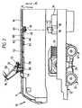
- FIGs 1 and 2 is a model railroad vehicle in shape an electric model locomotive, designated as a whole by reference number 10 shown that a lower part 12 and one on the lower part 12 includes attachable housing 14.
- the housing 14 forms a roof 16, on the top of which a known single-arm pantograph 18 is held in the usual way on the contact wire known and therefore not shown in the drawing electrical catenary can be applied.
- the pantograph can 18 between the raised position shown in Figure 1 and a retracted position. through a tension spring 20 is the pantograph 18 in the usual manner in the raised position biased.
- a fastening screw 22 the pantograph 18 can be screwed to the roof 16 become.
- the housing 14 can Model locomotive 10 placed on the lower part 12 and for disassembly be lifted off the lower part 12. This is indicated by the arrows 24 and 25 symbolized in Figure 2.
- a bogie 28 On the lower part 12 are a bogie 28 with a Electric motor 30 for moving the model locomotive 10 and wheels 32 held.
- the raising and lowering of the pantograph 18 can from Users of the model locomotive can be controlled.
- the drive roller 42 carries on its top 16 facing the roof a pin 44 which is integrally connected to the drive roller 42 and in an associated receptacle 46 on the underside of the Roof 16 rotatably mounted pulley 48 which engages in alignment to the axis of rotation 40 aligned axis of rotation 50 is freely rotatable.
- the drive roller 42 and Rope pulley 48 via the pin 44 and the receptacle 46 in a form-fitting manner connected.
- a non-positive connection could be used are used, for example by means of one another Magnets that are held on the drive roller 42 and the rope pulley 48.
- a two-part pull rope 52 held by a on the roof 16 below the pantograph 18 arranged through hole 54 is passed and with its end facing away from the pulley 48 on a pivot lever 56 of the pantograph 18 is fixed.
- the two parts of the pull rope 52 are attacked by a pantograph 18 first pull rope section 58 and one on the rope pulley 48 attached second pull rope section 60 formed by a mechanical Link 62 are connected together.
- On the link 62 are the mutually facing ends of the first and second pull cable sections 58 and 60 by means of clamping screws 64, 66 fixable.
- a traction cable guide 68 held in Combination with the roof underside a storage space 70 in vertical Limited direction through which the first pull rope section 58 passes is.
- the power supply of the drive motor 34 and the supply of Control signals to the drive motor 34 take place via the bogie 28, as well as the drive motor 34 on the lower part 12 of the model locomotive is held. This allows electrical connection lines from the lower part 12 to the housing 14 and the assembly of the Model locomotive 10 is particularly simple.
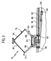
- FIG. 3 shows an alternative embodiment of a model locomotive 10 shown, which is denoted overall by the reference numeral 75, wherein identical components are designated with the same reference numerals as in the embodiment explained above.
- the model locomotive 75 differs from that with reference to the figures 1 and 2 embodiment shown in that instead of one Einholm roof pantograph a scissor pantograph 77 for Use comes with top scissors 79 and bottom scissors 81 are articulated together in the usual way and each first and have second pivot arms 83, 84 and 85, 86, respectively.
- the first Traction cable section 58 forms in the second embodiment shown in FIG a model locomotive below the roof 16 one Loop by being integral with the link 62 connected towing eye 88 is led around.
- the free ends of the first Pull rope section 58 are in each case through the model locomotive 75 a through hole 90 or 92 arranged on the roof 16 is passed through and on the first and second swivel arms 85, 86 of the Lower scissors 81 set.
- the second connected to the pulley 48 Traction cable section 60 is in accordance with the first exemplary embodiment held on the connecting member 62 by means of the clamping screw 66.
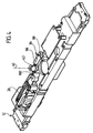
- FIG 4 is the lower part in a schematic diagram a third embodiment of a model locomotive according to the invention shown, again identical components with the same Reference numerals are designated as in the above under Referring to Figures 1 and 2 described first embodiment.
- the rotary drive of the drive roller 42 is shown in FIG 4 shown third embodiment, a piezoelectric actuator 94 for use with an oscillating member 96, which by means of a spring 98 is biased towards the drive roller 42, which is the spring 98 facing away from the free end of the vibrating member 96 at one with the Drive roller 42 connected bead 100 abuts.
- the vibrating link 96 can be applied to the piezoelectric actuator 94 excited to mechanical vibration are, with the free, on the bead 100 of the drive roller 42 End of the oscillating member 96 is essentially an elliptical Movement.
- the drive roller 42 becomes one Rotational movement about the axis of rotation 40 is driven. ever according to the electrical signal applied to the piezoelectric actuator 94, can change the direction of the rotational movement of the free end of the Vibrating member 96 and thus also the direction of rotation of the drive roller 42 can be changed.
- the vibrating member 96 is under the action the spring 98 on the bead 100 so that the drive roller 42 locks and thus the pantograph 18 or the scissor pantograph 77, with the pulley 48 and the pull rope 52 with the drive roller 42 is coupled, held in its respective position becomes.
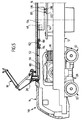
- FIG 5 Another alternative embodiment of a model locomotive is shown in FIG 5, wherein identical components with the same reference numerals are referred to as with reference to the figures 1 and 2 designated embodiment. In this respect, the foregoing Full reference to the content.
- a model train locomotive 110 is shown, which differs from the model train locomotive 10 differs in that a drive motor 134th is used, which is fixed to the underside of the roof 16 and via a known transmission, not shown in Figure 5 drives the pulley 48 rotating.
- the electrical power supply of the Drive motor 134 takes place via two on the underside of the drive motor 134 pins 135 and 136 held by the drive motor 134 stick down in the vertical direction and with their Free ends associated contact fields 137 and 138 of a circuit board Contact 140, which is fixed to the lower part 12.
- the circuit board 140 with electrical Power can be supplied, for example, by means of a known and therefore grinder not shown in the drawing can be tapped from the rail wheels 32.
- the contact pins 135 and 136 contact the associated Contact fields 137 and 138, so that an electrical connection from the drive motor 134 via the printed circuit board 140 to the lower part 12 is produced.
- FIG illustrated embodiment also a piezoelectric actuator on the Underside of the roof 16 are held, as illustrated in Figure 4 is.
- the vibrating element of the actuator is located directly on the Pulley 48 on.
- the vibrating link becomes a mechanical vibration excited, the pulley 48 is rotated.
Landscapes
- Toys (AREA)
Abstract
Description
- Figur 1:
- einen schematischen Längsschnitt eines erfindungsgemäßen Modellbahnfahrzeuges gemäß einer ersten Ausführungsform im montierten Zustand;
- Figur 2:
- einen schematischen Längsschnitt des Modellbahnfahrzeuges gemäß Figur 1 mit angehobenem Gehäuse;
- Figur 3:
- einen Teillängsschnitt eines erfindungsgemäßen Modellbahnfahrzeuges gemäß einer zweiten Ausführungsform;
- Figur 4:
- eine perspektivische Darstellung des Unterteiles eines erfindungsgemäßen Modellbahnfahrzeuges gemäß einer dritten Ausführungsform, und
- Figur 5:
- einen schematischen Längsschnitt eines erfindungsgemäßen Modellbahnfahrzeuges gemäß einer vierten Ausführungsform im montierten Zustand.
Claims (25)
- Modellbahnfahrzeug mit einem Unterteil und einem ein Dach ausbildenden Gehäuse, das auf das Unterteil aufsetzbar ist, sowie mit einem am Dach angeordneten Stromabnehmer, der über eine Antriebsverbindung mit einem elektrischen Antriebselement gekoppelt ist zum Anheben und Absenken des Stromabnehmers, dadurch gekennzeichnet, daß das elektrische Antriebselement (34; 94) am Unterteil (12) gehalten ist und daß die Antriebsverbindung eine Kupplungsvorrichtung (42, 48) umfaßt mit einem ersten, am Unterteil (12) gehaltenen Kupplungsteil (42) und einem zweiten, am Gehäuse (14) gehaltenen Kupplungsteil (48), wobei die beiden Kupplungsteile (42, 48) durch Aufsetzen des Gehäuses (14) auf das Unterteil (12) kraft- und/oder formschlüssig miteinander verbindbar sind.
- Modellbahnfahrzeug nach Anspruch 1, dadurch gekennzeichnet, daß die beiden Kupplungsteile (42, 48) um fluchtend zueinander ausgerichtete Drehachsen (40, 50) drehbar am Unterteil (12) bzw. am Gehäuse (14) gelagert sind.
- Modellbahnfahrzeug nach Anspruch 1 oder 2, dadurch gekennzeichnet, daß das erste Kupplungsteil als vom Antriebselement (34; 94) drehend antreibbare Antriebsrolle (42) ausgebildet ist.
- Modellbahnfahrzeug nach Anspruch 1, 2 oder 3, dadurch gekennzeichnet, daß das zweite Kupplungsteil als an der Unterseite des Dachs (16) drehbar gelagerte Abtriebsrolle (48) ausgebildet ist, die mit einem am Stromabnehmer (18; 77) angreifenden Zugglied (52) gekoppelt ist.
- Modellbahnfahrzeug mit den Merkmalen des Oberbegriffes des Anspruches 1, dadurch gekennzeichnet, daß das elektrische Antriebselement (134) am Gehäuse (14) gehalten ist und daß durch Aufsetzen des Gehäuses (14) auf das Unterteil (12) eine elektrische Verbindung herstellbar ist zwischen dem Antriebselement (134) und einem am Unterteil angeordneten Stromzuführungselement (140).
- Modellbahnfahrzeug nach Anspruch 5, dadurch gekennzeichnet, daß zur Herstellung der Verbindung zwischen Antriebselement (134) und Stromzuführungselement (140) am Gehäuse (14) und am Unterteil (12) elektrische Verbindungselemente (135, 136; 137, 138) gehalten sind, die durch Aufsetzen des Gehäuses (14) auf das Unterteil (12) in elektrischen Kontakt miteinander bringbar sind.
- Modellbahnfahrzeug nach Anspruch 6, dadurch gekennzeichnet, daß die Verbindungselemente Kontaktstifte (135, 136) umfassen, die bei auf dem Unterteil (12) aufgesetztem Gehäuse (14) korrespondierende Kontaktfelder (137, 138) kontaktieren.
- Modellbahnfahrzeug nach Anspruch 7, dadurch gekennzeichnet, daß die Kontaktfelder (137, 138) an einer Leiterplatte (140) angeordnet sind.
- Modellbahnfahrzeug nach Anspruch 8, dadurch gekennzeichnet, daß die Leiterplatte (140) am Unterteil (12) gehalten ist.
- Modellbahnfahrzeug nach Anspruch 7, 8 oder 9, dadurch gekennzeichnet, daß die Kontaktstifte (135, 136) in vertikaler Richtung ausgerichtet sind.
- Modellbahnfahrzeug nach einem der Ansprüche 7 bis 10, dadurch gekennzeichnet, daß die Kontaktstifte (135, 136) am Antriebselement (134) gehalten sind.
- Modellbahnfahrzeug nach einem der Ansprüche 5 bis 11, dadurch gekennzeichnet, daß das Antriebselement (134) an der Dachunterseite gehalten ist und eine Abtriebsrolle (48) drehend antreibt, die mit einem am Stromabnehmer (18) angreifenden Zugglied (52) gekoppelt ist.
- Modellbahnfahrzeug nach Anspruch 4 oder 12, dadurch gekennzeichnet, daß das Zugglied ein Zugseil (52) umfaßt, das am Stromabnehmer (18; 77) angreift und eine am Dach (16) angeordnete Durchgangsbohrung (54; 90, 92) durchgreift, und daß der Stromabnehmer (18; 77) durch eine Feder (20) in die angehobene Stellung vorgespannt ist.
- Modellbahnfahrzeug nach Anspruch 13, dadurch gekennzeichnet, daß die Abtriebsrolle eine Seilrolle (48) ausbildet zum Aufwickeln des Zugseils (52).
- Modellbahnfahrzeug nach Anspruch 13 oder 14, dadurch gekennzeichnet, daß das Zugseil (52) zweiteilig ausgestaltet ist mit einem am Stromabnehmer (18; 77) angreifenden ersten Zugseilabschnitt (58) und einem auf der Seilrolle (48) aufwickelbaren zweiten Zugseilabschnitt (60), wobei die beiden Abschnitte (58, 60) über ein Verbindungsglied (62) lösbar miteinander verbindbar sind.
- Modellbahnfahrzeug nach Anspruch 15, dadurch gekennzeichnet, daß der Stromabnehmer als Scherenstromabnehmer (77) ausgebildet ist mit einer Unterschere (81) und einer Oberschere (79), und daß die freien Enden des ersten Zugseilabschnittes (58) jeweils eine Durchgangsbohrung (90, 92) des Daches (16) durchgreifen und jeweils an einem Arm (85, 86) des Scherenstromabnehmers (77) angreifen, wobei der erste Zugseilabschnitt (58) unterhalb des Daches (16) eine Schlaufe ausbildet.
- Modellbahnfahrzeug nach einem der Ansprüche 13 bis 16, dadurch gekennzeichnet, daß der Durchgangsbohrung (54; 90, 92) benachbart an der Unterseite des Daches (16) eine Zugseilführung (68) gehalten ist.
- Modellbahnfahrzeug nach einem der voranstehenden Ansprüche, dadurch gekennzeichnet, daß das Antriebselement einen Elektromotor (34; 134) aufweist, der mit einem selbsthemmenden Getriebe (36) gekoppelt ist.
- Modellbahnfahrzeug nach Anspruch 18, dadurch gekennzeichnet, daß das Getriebe (36) eine Rutschkupplung (38) umfaßt.
- Modellbahnfahrzeug nach Anspruch 18 oder 19, dadurch gekennzeichnet, daß dem Elektromotor (34; 134) eine Stromüberwachungseinheit zugeordnet ist zur Überwachung des Motorstroms.
- Modellbahnfahrzeug nach einem der Ansprüche 1 bis 17, dadurch gekennzeichnet, daß das Antriebselement einen piezoelektrischen Aktor (94) umfaßt.
- Modellbahnfahrzeug nach Anspruch 21, dadurch gekennzeichnet, daß der piezoelektrische Aktor (94) ein zu einer mechanischen Schwingung aktivierbares Schwingglied (96) aufweist, das unmittelbar an das erste Kupplungsteil (42) oder an die Abtriebsrolle (48) federnd anlegbar ist.
- Modellbahnfahrzeug nach einem der voranstehenden Ansprüche, dadurch gekennzeichnet, daß dem Antriebselement (34; 94; 134) ein Endschalter und/oder ein Sensor zur Erkennung einer Endstellung des Stromabnehmers (18; 77) zugeordnet ist.
- Modellbahnfahrzeug nach Anspruch 23, dadurch gekennzeichnet, daß der Endschalter und/oder Sensor berührungslos arbeitet.
- Modellbahnfahrzeug nach einem der voranstehenden Ansprüche, dadurch gekennzeichnet, daß das Modellbahnfahrzeug mehrere Stromabnehmer aufweist, denen jeweils ein separates Antriebselement zugeordnet ist.
Applications Claiming Priority (2)
| Application Number | Priority Date | Filing Date | Title |
|---|---|---|---|
| DE20201703U | 2002-01-30 | ||
| DE20201703U DE20201703U1 (de) | 2002-01-30 | 2002-01-30 | Modellbahnfahrzeug |
Publications (2)
| Publication Number | Publication Date |
|---|---|
| EP1338314A1 true EP1338314A1 (de) | 2003-08-27 |
| EP1338314B1 EP1338314B1 (de) | 2005-12-14 |
Family
ID=7967371
Family Applications (1)
| Application Number | Title | Priority Date | Filing Date |
|---|---|---|---|
| EP03000845A Expired - Lifetime EP1338314B1 (de) | 2002-01-30 | 2003-01-15 | Modellbahnfahrzeug |
Country Status (3)
| Country | Link |
|---|---|
| EP (1) | EP1338314B1 (de) |
| AT (1) | ATE312655T1 (de) |
| DE (2) | DE20201703U1 (de) |
Families Citing this family (3)
| Publication number | Priority date | Publication date | Assignee | Title |
|---|---|---|---|---|
| FR2899126B1 (fr) * | 2006-03-29 | 2008-06-27 | Moreau Alain | Dispositif de commande d'une piece mobile d'un modele reduit |
| DE102006047971B4 (de) * | 2006-10-10 | 2008-07-31 | Modelleisenbahn Gmbh | Stellantrieb für Modelle oder Modellfahrzeuge |
| DE102008036184B4 (de) | 2008-08-04 | 2010-12-30 | Modelleisenbahn Gmbh | Antriebseinrichtung für Stromabnehmer eines Modellbahnfahrzeugs |
Citations (3)
| Publication number | Priority date | Publication date | Assignee | Title |
|---|---|---|---|---|
| DE1478580A1 (de) * | 1965-06-04 | 1969-10-09 | Maerklin & Cie Gmbh Geb | Oberleitungsstromabnehmer fuer Modellfahrzeuge |
| FR2435274A1 (fr) * | 1978-09-05 | 1980-04-04 | Lamoureux Christian | Modele reduit d'un trolleybus, echelle ho 1/87. principe de fonctionnement |
| DE3603026A1 (de) * | 1985-02-08 | 1986-08-14 | Carlo Filippo Chivasso Follis | Steuervorrichtung fuer die stromabnehmerbuegel von lokomotiven |
-
2002
- 2002-01-30 DE DE20201703U patent/DE20201703U1/de not_active Expired - Lifetime
-
2003
- 2003-01-15 AT AT03000845T patent/ATE312655T1/de active
- 2003-01-15 DE DE50301887T patent/DE50301887D1/de not_active Expired - Lifetime
- 2003-01-15 EP EP03000845A patent/EP1338314B1/de not_active Expired - Lifetime
Patent Citations (3)
| Publication number | Priority date | Publication date | Assignee | Title |
|---|---|---|---|---|
| DE1478580A1 (de) * | 1965-06-04 | 1969-10-09 | Maerklin & Cie Gmbh Geb | Oberleitungsstromabnehmer fuer Modellfahrzeuge |
| FR2435274A1 (fr) * | 1978-09-05 | 1980-04-04 | Lamoureux Christian | Modele reduit d'un trolleybus, echelle ho 1/87. principe de fonctionnement |
| DE3603026A1 (de) * | 1985-02-08 | 1986-08-14 | Carlo Filippo Chivasso Follis | Steuervorrichtung fuer die stromabnehmerbuegel von lokomotiven |
Also Published As
| Publication number | Publication date |
|---|---|
| DE20201703U1 (de) | 2002-05-08 |
| EP1338314B1 (de) | 2005-12-14 |
| ATE312655T1 (de) | 2005-12-15 |
| DE50301887D1 (de) | 2006-01-19 |
Similar Documents
| Publication | Publication Date | Title |
|---|---|---|
| DE19809710C2 (de) | Elektrisch betätigter Schiebetüraktuator | |
| EP0256975B1 (de) | Kupplungsvorrichtung an einem Fahrzeug zur Übertragung einer Zug- oder Stosskraft auf ein weiteres Fahrzeug | |
| DE2328624A1 (de) | Spielzeug, insbesondere spielfahrzeug mit federmotorantrieb und betaetigungseinrichtung | |
| DE102007060375A1 (de) | Schienengeführtes Mobilwandelement mit einem Wandkörper | |
| WO2023072365A1 (de) | Positioniereinheit für eine ladestation und verfahren zur kontaktierung | |
| DE4226304A1 (de) | Elektromotorischer Stelltrieb für verstellbare Aggregate an einem Kraftfahrzeug | |
| EP3269582A1 (de) | Nicht schienengebundenes elektrisch oder hybrid-elektrisch angetriebenes fahrzeug | |
| DE19720888A1 (de) | Modellfahrzeug, insbesondere Modelleisenbahnfahrzeug | |
| DE102019214662A1 (de) | Ladestation für einen fahrzeugseitigen Energiespeicher | |
| EP4021753A1 (de) | Positioniereinheit und verfahren zur kontaktierung | |
| EP1257450B1 (de) | Stützeinrichtung für fahrzeuge | |
| EP1338314B1 (de) | Modellbahnfahrzeug | |
| DE10347817B4 (de) | Anhängekupplung | |
| DE3832581A1 (de) | Deichsel fuer hubwagen und hublader | |
| DE3687343T2 (de) | Vorrichtung zum heben und senken einer trolleystange. | |
| EP4294666A1 (de) | Positioniereinheit und verfahren zur kontaktierung | |
| DE3503806C2 (de) | ||
| CH703049A2 (de) | Vorrichtung zum Anheben und Absenken von Lasten. | |
| DE3328807C2 (de) | ||
| DE3933640C2 (de) | ||
| DE102007036225A1 (de) | Antriebsvorrichtung für ein fahrbares Gerät sowie eine solche Antriebsvorrichtung enthaltendes fahrbares Gerät insbesondere akkumulatorbetriebener, selbständig verfahrbarer Staubsammelroboter | |
| DE69407673T2 (de) | Antriebseinheit für Kipptore | |
| WO2021047915A1 (de) | Exzenter-modulkoppelstelle | |
| DE2347279C3 (de) | Vorrichtung zum Antrieb oder Abbremsen von auf Schienen geführten Fahrzeugen, insbesondere Tunnelofenwagen | |
| DE10204539A1 (de) | Spielzeugmodell |
Legal Events
| Date | Code | Title | Description |
|---|---|---|---|
| PUAI | Public reference made under article 153(3) epc to a published international application that has entered the european phase |
Free format text: ORIGINAL CODE: 0009012 |
|
| AK | Designated contracting states |
Designated state(s): AT BE BG CH CY CZ DE DK EE ES FI FR GB GR HU IE IT LI LU MC NL PT SE SI SK TR |
|
| AX | Request for extension of the european patent |
Extension state: AL LT LV MK RO |
|
| 17P | Request for examination filed |
Effective date: 20031113 |
|
| 17Q | First examination report despatched |
Effective date: 20040127 |
|
| AKX | Designation fees paid |
Designated state(s): AT BE BG CH CY CZ DE DK EE ES FI FR GB GR HU IE IT LI LU MC NL PT SE SI SK TR |
|
| GRAP | Despatch of communication of intention to grant a patent |
Free format text: ORIGINAL CODE: EPIDOSNIGR1 |
|
| GRAS | Grant fee paid |
Free format text: ORIGINAL CODE: EPIDOSNIGR3 |
|
| GRAA | (expected) grant |
Free format text: ORIGINAL CODE: 0009210 |
|
| AK | Designated contracting states |
Kind code of ref document: B1 Designated state(s): AT BE BG CH CY CZ DE DK EE ES FI FR GB GR HU IE IT LI LU MC NL PT SE SI SK TR |
|
| PG25 | Lapsed in a contracting state [announced via postgrant information from national office to epo] |
Ref country code: IE Free format text: LAPSE BECAUSE OF FAILURE TO SUBMIT A TRANSLATION OF THE DESCRIPTION OR TO PAY THE FEE WITHIN THE PRESCRIBED TIME-LIMIT Effective date: 20051214 Ref country code: NL Free format text: LAPSE BECAUSE OF FAILURE TO SUBMIT A TRANSLATION OF THE DESCRIPTION OR TO PAY THE FEE WITHIN THE PRESCRIBED TIME-LIMIT Effective date: 20051214 Ref country code: CZ Free format text: LAPSE BECAUSE OF FAILURE TO SUBMIT A TRANSLATION OF THE DESCRIPTION OR TO PAY THE FEE WITHIN THE PRESCRIBED TIME-LIMIT Effective date: 20051214 Ref country code: FI Free format text: LAPSE BECAUSE OF FAILURE TO SUBMIT A TRANSLATION OF THE DESCRIPTION OR TO PAY THE FEE WITHIN THE PRESCRIBED TIME-LIMIT Effective date: 20051214 Ref country code: SI Free format text: LAPSE BECAUSE OF FAILURE TO SUBMIT A TRANSLATION OF THE DESCRIPTION OR TO PAY THE FEE WITHIN THE PRESCRIBED TIME-LIMIT Effective date: 20051214 Ref country code: GB Free format text: LAPSE BECAUSE OF FAILURE TO SUBMIT A TRANSLATION OF THE DESCRIPTION OR TO PAY THE FEE WITHIN THE PRESCRIBED TIME-LIMIT Effective date: 20051214 Ref country code: SK Free format text: LAPSE BECAUSE OF FAILURE TO SUBMIT A TRANSLATION OF THE DESCRIPTION OR TO PAY THE FEE WITHIN THE PRESCRIBED TIME-LIMIT Effective date: 20051214 Ref country code: IT Free format text: LAPSE BECAUSE OF FAILURE TO SUBMIT A TRANSLATION OF THE DESCRIPTION OR TO PAY THE FEE WITHIN THE PRESCRIBED TIME-LIMIT;WARNING: LAPSES OF ITALIAN PATENTS WITH EFFECTIVE DATE BEFORE 2007 MAY HAVE OCCURRED AT ANY TIME BEFORE 2007. THE CORRECT EFFECTIVE DATE MAY BE DIFFERENT FROM THE ONE RECORDED. Effective date: 20051214 |
|
| REG | Reference to a national code |
Ref country code: GB Ref legal event code: FG4D Free format text: NOT ENGLISH |
|
| REG | Reference to a national code |
Ref country code: CH Ref legal event code: EP |
|
| REG | Reference to a national code |
Ref country code: CH Ref legal event code: NV Representative=s name: ISLER & PEDRAZZINI AG |
|
| REG | Reference to a national code |
Ref country code: IE Ref legal event code: FG4D Free format text: LANGUAGE OF EP DOCUMENT: GERMAN |
|
| REF | Corresponds to: |
Ref document number: 50301887 Country of ref document: DE Date of ref document: 20060119 Kind code of ref document: P |
|
| PG25 | Lapsed in a contracting state [announced via postgrant information from national office to epo] |
Ref country code: MC Free format text: LAPSE BECAUSE OF NON-PAYMENT OF DUE FEES Effective date: 20060131 Ref country code: BE Free format text: LAPSE BECAUSE OF NON-PAYMENT OF DUE FEES Effective date: 20060131 Ref country code: LU Free format text: LAPSE BECAUSE OF NON-PAYMENT OF DUE FEES Effective date: 20060131 |
|
| PG25 | Lapsed in a contracting state [announced via postgrant information from national office to epo] |
Ref country code: BG Free format text: LAPSE BECAUSE OF FAILURE TO SUBMIT A TRANSLATION OF THE DESCRIPTION OR TO PAY THE FEE WITHIN THE PRESCRIBED TIME-LIMIT Effective date: 20060314 Ref country code: GR Free format text: LAPSE BECAUSE OF FAILURE TO SUBMIT A TRANSLATION OF THE DESCRIPTION OR TO PAY THE FEE WITHIN THE PRESCRIBED TIME-LIMIT Effective date: 20060314 Ref country code: SE Free format text: LAPSE BECAUSE OF FAILURE TO SUBMIT A TRANSLATION OF THE DESCRIPTION OR TO PAY THE FEE WITHIN THE PRESCRIBED TIME-LIMIT Effective date: 20060314 Ref country code: DK Free format text: LAPSE BECAUSE OF FAILURE TO SUBMIT A TRANSLATION OF THE DESCRIPTION OR TO PAY THE FEE WITHIN THE PRESCRIBED TIME-LIMIT Effective date: 20060314 |
|
| PG25 | Lapsed in a contracting state [announced via postgrant information from national office to epo] |
Ref country code: ES Free format text: LAPSE BECAUSE OF FAILURE TO SUBMIT A TRANSLATION OF THE DESCRIPTION OR TO PAY THE FEE WITHIN THE PRESCRIBED TIME-LIMIT Effective date: 20060325 |
|
| PG25 | Lapsed in a contracting state [announced via postgrant information from national office to epo] |
Ref country code: PT Free format text: LAPSE BECAUSE OF FAILURE TO SUBMIT A TRANSLATION OF THE DESCRIPTION OR TO PAY THE FEE WITHIN THE PRESCRIBED TIME-LIMIT Effective date: 20060515 |
|
| NLV1 | Nl: lapsed or annulled due to failure to fulfill the requirements of art. 29p and 29m of the patents act | ||
| PG25 | Lapsed in a contracting state [announced via postgrant information from national office to epo] |
Ref country code: HU Free format text: LAPSE BECAUSE OF FAILURE TO SUBMIT A TRANSLATION OF THE DESCRIPTION OR TO PAY THE FEE WITHIN THE PRESCRIBED TIME-LIMIT Effective date: 20060615 |
|
| GBV | Gb: ep patent (uk) treated as always having been void in accordance with gb section 77(7)/1977 [no translation filed] |
Effective date: 20051214 |
|
| REG | Reference to a national code |
Ref country code: IE Ref legal event code: FD4D |
|
| PLBE | No opposition filed within time limit |
Free format text: ORIGINAL CODE: 0009261 |
|
| STAA | Information on the status of an ep patent application or granted ep patent |
Free format text: STATUS: NO OPPOSITION FILED WITHIN TIME LIMIT |
|
| 26N | No opposition filed |
Effective date: 20060915 |
|
| EN | Fr: translation not filed | ||
| REG | Reference to a national code |
Ref country code: CH Ref legal event code: PCAR Free format text: ISLER & PEDRAZZINI AG;POSTFACH 1772;8027 ZUERICH (CH) |
|
| BERE | Be: lapsed |
Owner name: GEBRUDER MARKLIN & CIE. G.- MIT BESCHRANKTER HAFT Effective date: 20060131 |
|
| PG25 | Lapsed in a contracting state [announced via postgrant information from national office to epo] |
Ref country code: FR Free format text: LAPSE BECAUSE OF FAILURE TO SUBMIT A TRANSLATION OF THE DESCRIPTION OR TO PAY THE FEE WITHIN THE PRESCRIBED TIME-LIMIT Effective date: 20070202 |
|
| PG25 | Lapsed in a contracting state [announced via postgrant information from national office to epo] |
Ref country code: EE Free format text: LAPSE BECAUSE OF FAILURE TO SUBMIT A TRANSLATION OF THE DESCRIPTION OR TO PAY THE FEE WITHIN THE PRESCRIBED TIME-LIMIT Effective date: 20051214 |
|
| PG25 | Lapsed in a contracting state [announced via postgrant information from national office to epo] |
Ref country code: TR Free format text: LAPSE BECAUSE OF FAILURE TO SUBMIT A TRANSLATION OF THE DESCRIPTION OR TO PAY THE FEE WITHIN THE PRESCRIBED TIME-LIMIT Effective date: 20051214 |
|
| PG25 | Lapsed in a contracting state [announced via postgrant information from national office to epo] |
Ref country code: FR Free format text: LAPSE BECAUSE OF FAILURE TO SUBMIT A TRANSLATION OF THE DESCRIPTION OR TO PAY THE FEE WITHIN THE PRESCRIBED TIME-LIMIT Effective date: 20060131 |
|
| PG25 | Lapsed in a contracting state [announced via postgrant information from national office to epo] |
Ref country code: CY Free format text: LAPSE BECAUSE OF FAILURE TO SUBMIT A TRANSLATION OF THE DESCRIPTION OR TO PAY THE FEE WITHIN THE PRESCRIBED TIME-LIMIT Effective date: 20051214 Ref country code: FR Free format text: LAPSE BECAUSE OF FAILURE TO SUBMIT A TRANSLATION OF THE DESCRIPTION OR TO PAY THE FEE WITHIN THE PRESCRIBED TIME-LIMIT Effective date: 20051214 |
|
| PGFP | Annual fee paid to national office [announced via postgrant information from national office to epo] |
Ref country code: CH Payment date: 20130128 Year of fee payment: 11 |
|
| PGFP | Annual fee paid to national office [announced via postgrant information from national office to epo] |
Ref country code: AT Payment date: 20130128 Year of fee payment: 11 |
|
| REG | Reference to a national code |
Ref country code: CH Ref legal event code: PL |
|
| REG | Reference to a national code |
Ref country code: AT Ref legal event code: MM01 Ref document number: 312655 Country of ref document: AT Kind code of ref document: T Effective date: 20140115 |
|
| PG25 | Lapsed in a contracting state [announced via postgrant information from national office to epo] |
Ref country code: LI Free format text: LAPSE BECAUSE OF NON-PAYMENT OF DUE FEES Effective date: 20140131 Ref country code: CH Free format text: LAPSE BECAUSE OF NON-PAYMENT OF DUE FEES Effective date: 20140131 |
|
| PG25 | Lapsed in a contracting state [announced via postgrant information from national office to epo] |
Ref country code: AT Free format text: LAPSE BECAUSE OF NON-PAYMENT OF DUE FEES Effective date: 20140115 |
|
| REG | Reference to a national code |
Ref country code: DE Ref legal event code: R082 Ref document number: 50301887 Country of ref document: DE Representative=s name: HOEGER, STELLRECHT & PARTNER PATENTANWAELTE MB, DE |
|
| PGFP | Annual fee paid to national office [announced via postgrant information from national office to epo] |
Ref country code: DE Payment date: 20170224 Year of fee payment: 15 |
|
| REG | Reference to a national code |
Ref country code: DE Ref legal event code: R119 Ref document number: 50301887 Country of ref document: DE |
|
| PG25 | Lapsed in a contracting state [announced via postgrant information from national office to epo] |
Ref country code: DE Free format text: LAPSE BECAUSE OF NON-PAYMENT OF DUE FEES Effective date: 20180801 |