EP1338325A1 - Vorrichtung zur steuerung von dampfbewegung - Google Patents
Vorrichtung zur steuerung von dampfbewegung Download PDFInfo
- Publication number
- EP1338325A1 EP1338325A1 EP00963055A EP00963055A EP1338325A1 EP 1338325 A1 EP1338325 A1 EP 1338325A1 EP 00963055 A EP00963055 A EP 00963055A EP 00963055 A EP00963055 A EP 00963055A EP 1338325 A1 EP1338325 A1 EP 1338325A1
- Authority
- EP
- European Patent Office
- Prior art keywords
- closed space
- rotating body
- film
- ventilation passage
- separation film
- Prior art date
- Legal status (The legal status is an assumption and is not a legal conclusion. Google has not performed a legal analysis and makes no representation as to the accuracy of the status listed.)
- Withdrawn
Links
Images













Classifications
-
- B—PERFORMING OPERATIONS; TRANSPORTING
- B01—PHYSICAL OR CHEMICAL PROCESSES OR APPARATUS IN GENERAL
- B01D—SEPARATION
- B01D53/00—Separation of gases or vapours; Recovering vapours of volatile solvents from gases; Chemical or biological purification of waste gases, e.g. engine exhaust gases, smoke, fumes, flue gases, aerosols
- B01D53/22—Separation of gases or vapours; Recovering vapours of volatile solvents from gases; Chemical or biological purification of waste gases, e.g. engine exhaust gases, smoke, fumes, flue gases, aerosols by diffusion
-
- B—PERFORMING OPERATIONS; TRANSPORTING
- B01—PHYSICAL OR CHEMICAL PROCESSES OR APPARATUS IN GENERAL
- B01D—SEPARATION
- B01D53/00—Separation of gases or vapours; Recovering vapours of volatile solvents from gases; Chemical or biological purification of waste gases, e.g. engine exhaust gases, smoke, fumes, flue gases, aerosols
- B01D53/26—Drying gases or vapours
- B01D53/268—Drying gases or vapours by diffusion
-
- B—PERFORMING OPERATIONS; TRANSPORTING
- B01—PHYSICAL OR CHEMICAL PROCESSES OR APPARATUS IN GENERAL
- B01D—SEPARATION
- B01D63/00—Apparatus in general for separation processes using semi-permeable membranes
- B01D63/06—Tubular membrane modules
-
- B—PERFORMING OPERATIONS; TRANSPORTING
- B01—PHYSICAL OR CHEMICAL PROCESSES OR APPARATUS IN GENERAL
- B01D—SEPARATION
- B01D2313/00—Details relating to membrane modules or apparatus
- B01D2313/18—Specific valves
Definitions
- the present invention relates to a vapor movement control device (a humidity conditioning device) which is used as the humidity conditioning device or the like by controlling a moving direction of the vapor on the basis of a film body having an air permeability and a humidity permeability and an arrangement thereof.
- a vapor movement control device a humidity conditioning device
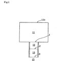
- a vapor movement control device in which a plurality of small chambers 12 and 13 sectioned by film bodies 1, 2 and 3 having an air permeability and a humidity permeability are formed between a closed space 11 formed inside a box body 11b and the outside air 15.
- a humidity conditioning in the closed space 11 is carried out by aligning a moving amount of the vapor with a fluctuation cycle of the outside air 15 in each of the small chambers 12 and 13 with utilizing permeability characteristics of the air and the vapor in a separating course, and determining a volumetric capacity of the closed space 11 and a volumetric capacity of each of the small chambers 12 and 13.
- a hollow fiber membrane is used so that a limit is hard to be generated on a surface area in the film bodies 1, 2 and 3 in the separating course, however, in this case, it is necessary to pressure feed a separated gas body by a pump, and it is a necessary condition that the pump is independently provided.
- the vapor movement control device having the basic structure as shown in Fig. 1 is advantageous in the case that the area of the film bodies 1, 2 and 3 is set small with respect to the volumetric capacity of the closed space 11 to be humidity-controlled, for the purpose of regulating a temperature. Accordingly, a limit is generated in the closed space 11 (the volumetric capacity) capable of conditioning the humidity. Further, since the condition for the humidity conditioning requires a temperature fluctuation of the outside air 15, and a periodic fluctuation of the temperature is used together with a pressure fluctuation of the closed space 11 utilizing a rapid increase of the temperature, a limit is generated in the humidity conditioning time and a time capable of controlling the movement of the vapor.
- a concentration gradient making good use of the temperature fluctuation is formed by pressure feeding from a ventilation passage 16 or sucking from a ventilation passage 17 by a pump or the like which is independently provided in an outer portion, and making good use of an adiabatic cooling phenomenon or an adiabatic expanding phenomenon which is generated at a time of this pressure fluctuation.
- the present invention is made for the purpose of solving the conventional problems mentioned above, and an object of the present invention is to provide a vapor movement control device which is small in size, is capable of fine-adjusting a separation efficiency by the revolution speed of amotor, is less in vibration, and is capable of saving energy remarkably by the utilization of a heating phenomenon of a rotary machine such as a motor.
- a vapor movement control device in accordance with the present invention is structured such that:
- the gas moving direction is limited to the vertical or passing direction with respect to the film bodies 1, 2 and 3. This point is common between the module constituted by the hollow fiber membrane as shown in Fig. 2, and the present invention.
- Fig. 3 there is considered a model in which the humidity of the closed space 11, the inner small chamber 12, the outer small chamber 13 and the outside air 15 (or an exhaust side space) is sectioned every 10 %.
- the film body is briefly referred to as reference symbol mb
- the film body 1 is briefly referred to as reference symbol 1mb
- the film body 2 is briefly referred to as reference symbol 2mb
- the film body 3 is briefly referred to as reference symbol 3mb.
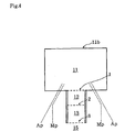
- FIG. 4 A description will be given of a model for describing the phenomenon of the movement of the vapor movement control device shown in Fig. 1, with reference to a schematic view shown in Fig. 4.
- reference symbol Ap denotes an air permeability (an inverse number of an air permeability)
- reference symbol Mp denotes a moisture permeability.
- properties of the air permeability and the moisture permeability only have a difference in transmitting amount between the film body 1 and the film body 2, however, are different between the film body 2 and the film body 3, and a difference in the air permeability is recognized between the film body 2 and the film body 3 in spite that the film body 2 and the film body 3 are not so different in the moisture permeability. Accordingly, in the case that the air containing the vapor passing through the film body 2 passes through the film body 3, a change appears in a physical environment.
- a difference in the air permeability is set in the film body 3 rather than the film body 1. Accordingly, on the assumption that a total amount of a fixed volumetric capacity of air passing through the film body 1 passes through the film body 2 and the film body 3, the volumetric capacity thereof may be expanded, so that the adiabatic cooling phenomenon may be generated. Further, in the movement from the film body 3 toward the film body 2 and the film body 1 corresponding to the movement in the reverse direction, the adiabatic compression phenomenon may be generated. Since the adiabatic compression or cooling is generated under the pressure fluctuation equal to or less than 50 mb, the adiabatic compression or cooling can inhibit the temperature increase and promote the movement of the vapor.
- the applicant of the present invention pays attention to an electric field of a surface affected by a specific surface potential held in the film body, and can arrange a conductive porous body close to the film body forming a boundary face forming a temperature incline with respect to an influence by a static electricity and fine-adjust them.
- the temperature fluctuation of the outside air 15 with respect to the closed space 11 making good use of this characteristic amounts to much, and the speed difference and the cycle in the change of temperature between the closed space 11 and the outside air 15 are important factors for determining the moving direction of the vapor.
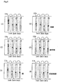
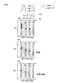
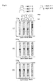
- Each of square pieces corresponds to 10 % moisture in the same manner as Fig. 3, and it is individually assumed that all of the closed space 11, the inner small chamber 12, the outer small chamber 13 and the outside air 15 reach a state in which they are all stable in a steady state, and the closed space 11 or the outside air 15 is 10 % lowered.
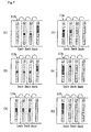
- Fig. 6 shows a case that the closed space 11 changes to 100 % and the outside air 15 changes to 50 %. Further, in the same manner, from a certain time point, in Fig. 7, it is assumed that the closed space 11 becomes 50 % and the outside air 15 is given a condition of 100 %.
- Steps of the respective movements are sectioned and arranged in Figs. 6 ((1) to (6)), and Fig. 7 ((1) to (6)) as the schematic views.
- the pressure fluctuation of the outside air 15 is not generated in the movement from the closed space 11 to the outside air 15. That is, in the movement of the vapor from the small chamber 13 to the outside air 15, the pressure fluctuation does not appear in the outside air 15.
- Fig. 8 ((1) to (3)) and Fig. 9 ((1) to (3)) are the limiting factor of the boundary film to which a condition having a difference between the moisture permeability (mp) and the air permeability (ap) is added.
- the moving direction is a direction of reducing the pressure of the closed space 11 in Fig. 8, and is a direction of increasing the pressure of the closed space 11 in Fig. 9.
- the closed space 11 tends to be stable in a concentration three pieces lower than the outside air 15 which is not limited in the pressure fluctuation, due to the movement in two directions, in the case of this arrangement relation.
- FIG. 12 A schematic arrangement view with respect to the air permeability and the moisture permeability in Fig. 4 in this case is shown in Fig. 12. In this case, it is assumed that the small chambers 12 and 13 in Fig. 12 are not changed.
- the moving vapor In accordance with the temperature descent, the moving vapor generates the dew point descent in addition to the pressure fluctuation, and generates the dewpoint ascent in correspondence to the temperature ascent.
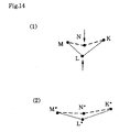
- each of the dew points shown in Fig. 13 and Fig. 14 ((1), (2)) is expressed as a ratio on an enthalpy curve.
- reference symbols N and L shown in Fig. 14 (1) tend to be low affected by the film body 2 as shown in Fig. 14 (2), in the case that the moving speed between reference symbols K and M is high, that is, in the case that the moving speed at a time of passing through the film body 2 after passing from the film body 1 through the film body 3, or at a time of passing through the film body 1 after passing from the film body 2 through the film body 3.
- reference symbols N and L tend to be high affected by the film body 2 as shown in Fig. 14 (2), in the case that the moving speed between reference symbols K and M is low, that is, in the case that the moving speed at a time of passing through the film body 2 after passing from the film body 1 through the film body 3, or at a time of passing through the film body 1 after passing from the film body 2 through the film body 3, and tend to be high affected by the incline of the thermal energy in the small chamber 12 and the small chamber 13.
- An absolute humidity fluctuation graph in Fig. 33 corresponds to the temperature fluctuation in Fig. 34, however, an ascent of the concentration is generated at the same time when the pressure ascent of the closed space 11 is generated in correspondence to the ascent of the temperature, so that the pressure ascent of about 50 mb is generated. That is, a change due to the pressure fluctuation accompanying with the ascent of the temperature appears.
- this device utilizes the matter that the same change can be achieved only by changing the pressure, and it is possible to restrict a calorific power to the minimum so as to control the movement of the vapor.
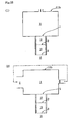
- Fig. 15 ((1), (2)) a system which carries out a pressure feeding by making good use of the boundary film on the flat surface shown in Fig. 2, in Fig. 1.
- a system shown in Fig. 15 (1) is put under the control of a hole diameter of the film body to be passed through, it is directly affected, for example, by dusts, oil mists or the like in the air.
- Fig. 15 (2) shows a path in the case that a side sub passage is provided, the surface of the film body 1 is fanned by the air passing from a ventilation passage 4 through a ventilation passage 6 in this case, and tends to be exposed to the temperature fluctuation in a portion corresponding to the film body 1 in the drawing.
- a vapor movement control device which uses a centrifugal force generating the pressure, promoting the vapor movement of the film body with using the pressure increase due to the centrifugal force, and utilizes regulation of the thermal energy transmission speed due to an agitation and the vapor movement speed difference between the film bodies due to the temperature fluctuation.
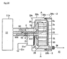
- Fig. 16 is a cross sectional view showing a vapor movement control device in accordance with a first embodiment of the present invention
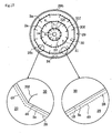
- Fig. 17 is a schematic cross sectional view of a separation film rotating body 28 along a line A-A in Fig. 16
- Fig. 18 is a side elevational view of the separation film rotating body 28.
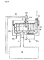
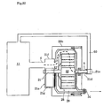
- This vapor movement control device is structured such that a first closed space 11 formed inside a box body 11b to be humidity-controlled and a second closed space 29 formed inside a casing 29b are communicated through a first ventilation passage 4, a separation film rotating body 28 in which a plurality of tubular film bodies 1a, 2a and 3a formed by film bodies having an air permeability and a humidity permeability and having different diameters are arranged on the same rotating axis 21 is pivotally supported in the second closed space 29, a plurality of small chambers 30 and 31 and an innermost space 32 sectioned by the respective tubular film bodies 1a, 2a and 3a are formed in the separation film rotating body 28, sirocco fans 30f, 31f and 32f promoting generation of a centrifugal force of the inward existing gas are mounted, and a centrifugal fin 7 (of a turbo screw type) is provided on the side surface thereof, a heat transfer member 21b transferring heat from a motor 21a (a rotating machine) of the separation film rotating body 28 to the
- the number of the small chambers is at least one, and in the case of one chamber, the small chamber is sectioned by using two tubular film bodies having different diameters.
- Glass wool or granular bodies ( ⁇ 2 to 5 mm) of expanded polystyrene spherical bodies may be received as a heat insulating material within the small chamber, or an alumina treatment may be applied as a rust proofing to the fins, the frames and the like within the small chamber.
- the rotation shaft 21 is made of a stainless steel, and the temperature is transmitted from the rotation shaft 21 to the separation film rotating body 28 from the motor 21a through the heat transfer member 21b, or from the rotation shaft 21 to the casing 29b, thereby forming the temperature incline within the small chambers 30 and 31 and the innermost space 32.
- a heat buffering body may be provided so as to oppose to a side surface of the separation film rotating body 28 with keeping a gap or may be provided integrally in the side surface of the separation film rotating body 28.
- a bore diameter of the first ventilation passage 4 is formed larger than a bore diameter of the second ventilation passage 6, thereby inhibiting the pressure reduction in the second closed space 29.
- the casing 29b is covered by a heat insulating layer 29c, and the separation film rotating body 28 rotates around the rotation shaft 21 by the motor 21a (the rotating machine) mounted so as to be in close contact with this heat insulating layer 29c.
- the heat is transferred to the casing 29b and the rotation shaft 21 from the motor 21a via the heat transfer member 21b.
- the structure may be made such as to shield the heat transmission to the rotation shaft 21, or the structure may be made such that the heat transmission from the heat transfer member 21b is applied to the bearing.
- a magnetic fluid may be employed as a seal member between the bearing and the rotation shaft 21a.
- the motor 21a a three-phase motor, a direct-current brushless core-less motor and the like may be employed as a drive rotating machine in which a direction of rotation can be reciprocated.
- the casing 29b is structured such as to be dissembled at a time of assembling or dissembling the separation film rotating body 28 by fastening a lid member 29b-2 to a main body member 29b-1 by a screw 29b-3.
- a corner portion of the casing 29b is beveled so as to make an air stream in the inside second closed space 29 smooth, thereby preventing a waterdrop reserving failure.
- the separation film rotating body 28 is formed detachable with respect to the rotation shaft 21.
- the attaching and detaching structure in Figs. 18 and 19 is structured such that a base 70 of a centrifugal fin 7 is integrally formed with the separation film rotating body 28, and three engagement pieces 22 are radially provided in a leading end of the rotation shaft 21 in a protruding manner. Further, three engagement grooves 71 detachably engaging with the respective engagement pieces 22 are radially formed in an inner periphery of an axial hole 72 formed in the base 70, and the structure is made such that the engagement pieces 22 are fitted into the engagement grooves 71 so as to be engaged therewith by inserting the engagement pieces 22 into the axial hole 72 and rotating the engagement pieces 22 at a fixed angle.
- reference numeral 73 denotes a screw for a stopper.
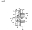
- the attaching and detaching structure in Fig. 20 is structured such that the base 70 of the centrifugal fin 7 is integrally formed with the rotation shaft 21, and three engagement pieces 22 are radially provided in a side surface of the separation film rotating body 28 in a protruding manner. Further, three engagement grooves 71 detachably engaging with the respective engagement pieces 22 are radially formed in the inner periphery of the axial hole 72 formed in the base 70, and the structure is made such that the engagement pieces 22 are fitted into the engagement grooves 71 so as to be engaged therewith by inserting the engagement pieces 22 into the axial hole 72 and rotating the engagement pieces 22 at a fixed angle.
- Each of the tubular film bodies 1a, 2a and 3a are formed by setting up a film body on an polygonal (a dodecagon) aluminum frame body 48, a conductive porous body or a non-conductive porous body 49 is set up with keeping a slight interval in an outer periphery of each of the tubular film body 1a, 2a and 3a, and the sirocco fins 30f, 31f and 32f are integrally mounted to the respective frame bodies 48.
- the film bodies 1a, 2a and 3a are supported by the frame body 48 so as not to strained by the centrifugal force at the rotating time, thereby preventing the air permeability and the moisture permeability from being denatured.
- the non-conductive porous body 49 can obtain an effect of canceling a temperature unevenness in a circumference of the separation film rotating body 28, in the case that the non-conductive porous body 49 is constituted by a material having a high thermal conductivity. Further, it is possible to obtain an effect of maintaining a shape obtained by an extension of a water absorbed or moisture absorbed film body from a shape obstructing the rotation.
- Each of the small chambers 30 and 31 and the innermost space 32 is agitated by the sirocco fins being below each of the space approximate cross sectional areas, and has an effect of promoting the generation of the centrifugal force of the inward existing gas and making it hard to generate the concentration difference.
- the conductive porous body or the non-conductive porous body may be set up with keeping a slight interval in the inner periphery of the tubular film bodies 1a, 2a and 3a.
- a ground wire 21c for grounding an electrostatic charge of the non-conductive porous body 49 is extended from the motor 21a so as to be wired.
- tubular film body 1a shown in Fig. 21 (1), the tubular film body 2a shown in Fig. 21 (2) and the tubular film body 3a shown in Fig. 21 (3) is formed in a three-layer structure.
- the tubular film body 1a has the three-layer structure in which a laminate structure is constructed by laminating a center special porous film 1a-1 by a nylon non woven fabric 1a-2 and a PE porous film 1a-3.
- the tubular film body 2a has the three-layer structure in which a laminate structure is constructed by laminating a center special porous film 2a-1 by a polyolefin non woven fabric 2a-2 and a PE porous film 2a-3.
- the tubular film body 3a has the three-layer structure in which a laminate structure is constructed by laminating a center special porous film 3a-1 by a polyolefin non woven fabric 3a-2 and a PE porous film 3a-3.
- PE porous film As the other materials, it is possible to use a PE porous film, a polyolefin non woven fabric. a polyurethane or the like.
- Fig. 22 ((1), (2)) shows a positional relation between positions of the first ventilation passage 4 and the outside air ventilation passage 34 and the separation film rotating body 28.
- an interval T1 and an interval T2 are set so that the outermost peripheral corner portion 28a and the outermost peripheral flat portion 28b of the separation film rotating body 28 do not lap over the outside air ventilation passage 34.
- Fig. 24 shows another embodiment of the separation film rotating body 28.
- each of the tubular film bodies 1a, 2a and 3a is formed by setting up the film body on the circular frame body 48, a sirocco fin 32f is provided only in the innermost space 32, and the partition wall 28c is radially formed from the sirocco fin 32f so as to section the small chambers 30 and 31 into a plurality of small chamber sections.
- an outer width and an inner width of the sirocco fin may be changed. Accordingly, it is possible to promote the generation of the temperature incline between the small chambers by applying the incline to a pressure application state of the inside gas in the outer small chamber section and the inner small chamber section and obtaining the pressure application incline.
- the pressure fluctuation in the second closed space 29 is hard to be generated in correspondence to the rotation of the separation film rotating body 28.
- the sirocco fin may be provided, for example, only in the small chamber 30 as far as the sirocco fin promotes the generation of the centrifugal force of the inside existing gas.
- the partition wall 28c is formed without trouble, for example, it is possible to make the interval of the partition wall 28c further narrow, the partition wall 28c may be provided not radially in a radial direction, but radially in an oblique direction shifted from a center of the separation film rotating body 28, and a lot of tube bodies may be radially provided between the tubular film body 1a and the tubular film body 2a and between the tubular film body 2a and the tubular film body 3a, thereby flowing the gas between the innermost space 32 and the outer periphery of the separation film rotating body 28.
- Figs. 25 to 28c structure provided radially in the oblique direction shifted from the center of the separation film rotating body 28.
- Fig. 25 shows a structure in which the partition wall 28c is arranged spirally, and shows an example in which each of the small chamber sections from the second closed space 29 including the high pressure generated by the centrifugal fin 7 run into the innermost space 32 tends to move from the innermost space 32 to the second closed space 29 with respect to the rotation direction at a high possibility. It is possible to obtain an effect of regulating the pressure incline of the path from the second closed space 29 run into the innermost space 32 so as to promote the smooth vapor movement, at a time when the inside gas in the small chamber section moves from the center to the outer periphery in correspondence to the rotation of the separation film rotating body 28.
- Fig. 26 shows an example in which the partition wall 28c is provided in the inverse direction to that of the case in Fig. 25.
- the partition wall 28c having the surface in a scooping direction from the outer periphery with respect to the rotation direction, it is possible to prevent the matter that the moving amount of the vapor becomes too large and the dew condensation is generated, and the vapor is discharged as the water from the outside air ventilation passage 34. That is, owing to these partition wall 28c, it is possible to obtain a force opposing to the centrifugal force, as shown in Fig. 26.
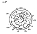
- Fig. 27 shows an example in which the partition wall 28c in Fig. 25 is separated between the respective small chambers 30 and 31 so as to be arranged in a shifted manner
- Fig. 28 shows an example in which the partition wall 28c in Fig. 26 is separated between the respective small chambers 30 and 31 so as to be arranged in a shifted manner. Accordingly, it is possible to regulate the agitating effect which applies an affect of the air stream to each other between the small chambers 30 and 31.
- the bore diameter of the first ventilation passage 4 and the bore diameter of the second ventilation passage 6 are not limited in size, it is possible to regulate the flow rate by arranging valves 6a and 34a for regulating the flow rate of the second ventilation passage 6 (a side sub circulating port) and the outside air ventilation passage 34, for example, a pinch valve, a needle valve or the like, and it is possible to smoothly circulate the air by making the bore diameter of the second ventilation passage 6 larger than the bore diameter of the first ventilation passage 4.
- the gas entering from the first ventilation passage 4 flows into the second closed space 29 by being applied the centrifugal force by the centrifugal fan 7, and is partly discharged to the outside air from the outside air ventilation passage 34 while coming across the rotation of the separation film rotating body 28.
- the separation film rotating body 28 since within the separation film rotating body 28, the small chambers 30 and 31 and the innermost space 32 are sectioned by the tubular film bodies 1a, 2a and 3a, the movement of the inside air caused by the centrifugal force toward the small chambers 30 and 31 in the case of the low speed rotation which is below the rotation applied by the centrifugal fan 7, so that the pressure reduction may be generated in the innermost space 32 and the second ventilation passage 6.
- the surface of the separation film rotating body 28 is exposed to the cooling, and the adiabatic cooling is generated in the order of the small chamber 30, the small chamber 31 and the innermost space 32.
- the film body 2 and the film body 3 is set to the arrangement of the films 30m, 31m and 32m
- the vapor causes to ascend the dew point in the case of flowing from the small chamber 30 toward the innermost space 32 rather than the case of flowing from the innermost space 32 toward the small chamber 30, and gets free from the factor obstructing the passing of the film. Accordingly, the movement from the small chamber 30 toward the innermost space 32 gradually overcomes, and the vapor is discharged from the outside air ventilation passage 34 to the outside air 15.
- a vapor pressure in K and a vapor pressure in M can be described as a phenomenon in which an inverse penetration phenomenon caused by an application of a pressure in an opposing direction to a moving pressure of the air corresponding to a medium having a pressure increased by the centrifugal force increased in accordance with the incline of the separation film rotating body 28 is generated by the water content formed on the film body surface.
- a Knudsen diffusion or a selective penetration is not generated in the film body having the large bore diameter mentioned above, however, it is possible to generate such an effect by using the dew condensation or a hygroscopic property.
- These films have a high durability against the water, and are inexpensive.
- a cavity body such as an expanded polystyrene corresponding to a porous body made of a flame retardant material, PE, PV having a low water absorbing property and the like, an aluminum lump or the like which tends to form the temperature incline in the small chambers 30 and 31 and the innermost space 32 may be employed for the material of the casing 29b, the separation film rotating body 28 and the like. Further, in order not to promote the temperature incline of the small chambers 30 and 31 and the innermost space 32 at a time of rotating, the material may be changed between the outer peripheral portion and the inner side of the separation film rotating body 28, thereby preventing the temperature incline from being generated.
- PE flame retardant material
- the moisture conditioning is carried out in such a manner as to discharge the vapor from the closed space 11 to the outside air 15 through the separation film rotating body 28 and the outside air ventilation passage 34, and in the case of rotating inversely, the moisture conditioning is carried out in such a manner as to take the vapor in the closed space 11 from the outside air 15 through the outside air ventilation passage 34 and the separation film rotating body 28.
- the forward rotation and the backward rotation are selected as occasion demands.
- the structure is made such that a cleaning water is taken inside the separation film rotating body 28 on the basis of a back flow generated by inverse rotating the separation film rotating body 28, by using a turbo fin provided with a spiral curve in the centrifugal fin 7 so as to generate the back flow at a time of cleaning the dusts or the like attached to the separation film rotating body 28, it is possible to wash out the dusts or the like attached to the separation film rotating body 28.
- Fig. 29 is a cross sectional view showing the other embodiment of the vapor movement control device.
- the innermost space 32 of the separation film rotating body 28 is communicated with the first closed space 11 through the second ventilation passage 6 formed inside a rotation shaft 21d and a circulating passage 60.
- the rotation shaft connected to the motor 21a is formed solid, and the rotation shaft 21d and the circulating passage 60 are connected through a rotation joint 21e.
- the other structures are the same as the vapor movement control device in Fig. 16.
- Figs. 30 and 31 show cases that the vapor movement control device in Fig. 29 is placed in different directions.
- the outside ventilation passage 34 and the second ventilation passage 6 are arranged so as to be hard to be under the trouble that the water is stored by the dew condensation, however, in the case of placing outdoor, it is necessary to attach a sun shade or a drip proof type umbrella to the outside ventilation passage 34.
- reference symbol 23b in the drawing denotes a drain port.
- the air filter or the drip proof type umbrella may be provided in the first ventilation passage 4 and the outside air ventilation passage 34.
- the number, the position and the direction of the outside air ventilation passage 34 can be optionally set.
- Fig. 32 is a cross sectional view showing the other embodiment of the vapor movement control device.
- the first ventilation passage 4 is formed in such a manner as to be communicated with the second closed space 29 through an inner side of a motor casing 21f in a state of avoiding a motor driving portion 21g of the motor 21a.
- the other structures are the same as those of the vapor movement control device in Fig. 29.
- a flow meter 90 is provided bypassing between the second ventilation passage 6 and the first ventilation passage 4, as a structure for testing the vapor movement control device.
- This flow meter 90 is used as a means for measuring the state of the air stream in the second ventilation passage 6 accompanying with the rotation of the separation film rotating body 28, and is set so that a float 90a provided in an inner portion is positioned at a middle position in a normal state. In the case that a turbulence is generated in the state of the air stream, the float 90a moves upward or downward, whereby an abnormal state can be comprehended on the basis of the moving direction.
- the state of the air stream in the second ventilation passage 6 caused by the rotation of the separation film rotating body 28 is measured by the flow meter 90 while rotating the separation film rotating body 28.
- the circulation of the air stream is generated in the order of the first closed space 11, the first ventilation passage 4, the second closed space 29, the separation film rotating body 28, the second ventilation passage 6 and the first closed space 11, and in the case that the plugging is generated in the tubular film bodies 1a, 2a and 3a of the separation film rotating body 28 due to the dusts or the like which are made into intrusion from the outside air, at this time, the flow rate of the second ventilation passage 6 is reduced in comparison with the normal time, so that the leak of the air stream is generated from the first ventilation passage 4 to the second ventilation passage 6 through the bypass, whereby the float 90a moves downward from the middle position.
- the flow rate of the second ventilation passage 6 is increased in comparison with the normal time, so that the leak of the air stream is generated from the second ventilation passage 6 to the first ventilation passage 4 through the bypass, whereby the float 90a moves upward from the middle position.
- a vapor movement control device which is small in size, is capable of fine-adjusting a separation efficiency by the revolution speed of a separation film rotating body, is less in vibration, and is capable of saving energy remarkably by the utilization of a heating phenomenon of a rotary machine such as a motor for rotating the separation film rotating body.
Landscapes
- Chemical & Material Sciences (AREA)
- Chemical Kinetics & Catalysis (AREA)
- Engineering & Computer Science (AREA)
- Analytical Chemistry (AREA)
- General Chemical & Material Sciences (AREA)
- Oil, Petroleum & Natural Gas (AREA)
- Separation Using Semi-Permeable Membranes (AREA)
- Drying Of Gases (AREA)
- Centrifugal Separators (AREA)
- Structures Of Non-Positive Displacement Pumps (AREA)
Applications Claiming Priority (1)
| Application Number | Priority Date | Filing Date | Title |
|---|---|---|---|
| PCT/JP2000/006855 WO2002028511A1 (fr) | 2000-10-02 | 2000-10-02 | Dispositif permettant de réguler le mouvement des vapeurs |
Publications (2)
| Publication Number | Publication Date |
|---|---|
| EP1338325A1 true EP1338325A1 (de) | 2003-08-27 |
| EP1338325A4 EP1338325A4 (de) | 2004-12-01 |
Family
ID=11736553
Family Applications (1)
| Application Number | Title | Priority Date | Filing Date |
|---|---|---|---|
| EP00963055A Withdrawn EP1338325A4 (de) | 2000-10-02 | 2000-10-02 | Vorrichtung zur steuerung von dampfbewegung |
Country Status (4)
| Country | Link |
|---|---|
| EP (1) | EP1338325A4 (de) |
| JP (1) | JP4327451B2 (de) |
| CA (1) | CA2424516A1 (de) |
| WO (1) | WO2002028511A1 (de) |
Families Citing this family (2)
| Publication number | Priority date | Publication date | Assignee | Title |
|---|---|---|---|---|
| CN113390225B (zh) * | 2020-03-11 | 2022-11-22 | 青岛海尔电冰箱有限公司 | 储物装置、储物装置的控制方法和冰箱 |
| CN115486506B (zh) * | 2022-09-26 | 2024-05-14 | 漳州市绿颖生物科技有限公司 | 一种金线莲饮料及其制备方法 |
Family Cites Families (3)
| Publication number | Priority date | Publication date | Assignee | Title |
|---|---|---|---|---|
| JP3537166B2 (ja) * | 1993-07-03 | 2004-06-14 | 株式会社九州山光社 | 除湿装置 |
| JP3682320B2 (ja) * | 1995-05-24 | 2005-08-10 | 株式会社九州山光社 | 除湿装置 |
| JP4064501B2 (ja) * | 1997-08-26 | 2008-03-19 | 株式会社九州山光社 | 水蒸気移動制御装置 |
-
2000
- 2000-10-02 EP EP00963055A patent/EP1338325A4/de not_active Withdrawn
- 2000-10-02 CA CA002424516A patent/CA2424516A1/en not_active Abandoned
- 2000-10-02 JP JP2002532331A patent/JP4327451B2/ja not_active Expired - Fee Related
- 2000-10-02 WO PCT/JP2000/006855 patent/WO2002028511A1/ja not_active Ceased
Also Published As
| Publication number | Publication date |
|---|---|
| CA2424516A1 (en) | 2003-04-02 |
| JPWO2002028511A1 (ja) | 2004-02-12 |
| WO2002028511A1 (fr) | 2002-04-11 |
| EP1338325A4 (de) | 2004-12-01 |
| JP4327451B2 (ja) | 2009-09-09 |
Similar Documents
| Publication | Publication Date | Title |
|---|---|---|
| CN107421005B (zh) | 轻便窗式空调器 | |
| US4727931A (en) | Air exchanging apparatus and method | |
| EP3833909B1 (de) | Belüftungsvorrichtung und system zur kanalfreien umgekehrten belüftung von gebäuden | |
| CN107314461A (zh) | 净化除湿机 | |
| JP2008215795A (ja) | 可動式熱交換方式とそれを応用した、エアーコンディショナー、貯湯器、扇風機、その他熱交換器、熱の交換方式 | |
| JP2006337015A (ja) | 全熱交換器及びこれを用いた換気システム | |
| CN202044802U (zh) | 冷凝式油雾净化机 | |
| US6062296A (en) | Regenerative heat recovery unit comprising heat accumulators tiltably movable to have a valve function | |
| CN102430256A (zh) | 冷凝式油雾净化机 | |
| CN206973746U (zh) | 净化除湿机 | |
| CA2424516A1 (en) | Vapor movement control device | |
| CN214626711U (zh) | 一种水油组合冷却的减速电机机座 | |
| JP2001504202A (ja) | 蓄熱式熱交換機 | |
| JP4547075B2 (ja) | 水蒸気移動制御装置 | |
| CN1997857A (zh) | 转动型热回收通风装置 | |
| KR100625021B1 (ko) | 가변형 열교환 환기장치 | |
| JP2002102663A (ja) | 水蒸気移動制御装置の検査方法 | |
| KR102274236B1 (ko) | 공기송풍장치, 공기송풍장치를 포함하는 공기송풍 시스템 | |
| KR101678665B1 (ko) | 멤브레인을 갖는 에너지 절약형 공기조화기 | |
| CN108087331A (zh) | 一种低噪音扇叶机构以及冷风机 | |
| CN113310157A (zh) | 具有微湿度调节功能的新风换气机 | |
| CN113624552A (zh) | 一种近海域水体样本采集系统 | |
| CN120169648B (zh) | 一种直热式油漆烘干房 | |
| KR101155253B1 (ko) | 열교환식 환기장치 | |
| KR102819421B1 (ko) | 공기조화용 에어 서큘레이터 |
Legal Events
| Date | Code | Title | Description |
|---|---|---|---|
| PUAI | Public reference made under article 153(3) epc to a published international application that has entered the european phase |
Free format text: ORIGINAL CODE: 0009012 |
|
| 17P | Request for examination filed |
Effective date: 20030502 |
|
| AK | Designated contracting states |
Designated state(s): AT BE CH CY DE DK ES FI FR GB GR IE IT LI LU MC NL PT SE |
|
| RBV | Designated contracting states (corrected) |
Designated state(s): CH DE FI GB LI |
|
| A4 | Supplementary search report drawn up and despatched |
Effective date: 20041020 |
|
| STAA | Information on the status of an ep patent application or granted ep patent |
Free format text: STATUS: THE APPLICATION IS DEEMED TO BE WITHDRAWN |
|
| 18D | Application deemed to be withdrawn |
Effective date: 20050114 |