EP1338367B1 - Dispositif de fixation d'une pièce de travail - Google Patents
Dispositif de fixation d'une pièce de travail Download PDFInfo
- Publication number
- EP1338367B1 EP1338367B1 EP03250561A EP03250561A EP1338367B1 EP 1338367 B1 EP1338367 B1 EP 1338367B1 EP 03250561 A EP03250561 A EP 03250561A EP 03250561 A EP03250561 A EP 03250561A EP 1338367 B1 EP1338367 B1 EP 1338367B1
- Authority
- EP
- European Patent Office
- Prior art keywords
- workpiece
- fixture
- arms
- lever
- recited
- Prior art date
- Legal status (The legal status is an assumption and is not a legal conclusion. Google has not performed a legal analysis and makes no representation as to the accuracy of the status listed.)
- Expired - Lifetime
Links
Images




Classifications
-
- B—PERFORMING OPERATIONS; TRANSPORTING
- B23—MACHINE TOOLS; METAL-WORKING NOT OTHERWISE PROVIDED FOR
- B23H—WORKING OF METAL BY THE ACTION OF A HIGH CONCENTRATION OF ELECTRIC CURRENT ON A WORKPIECE USING AN ELECTRODE WHICH TAKES THE PLACE OF A TOOL; SUCH WORKING COMBINED WITH OTHER FORMS OF WORKING OF METAL
- B23H11/00—Auxiliary apparatus or details, not otherwise provided for
- B23H11/003—Mounting of workpieces, e.g. working-tables
-
- B—PERFORMING OPERATIONS; TRANSPORTING
- B33—ADDITIVE MANUFACTURING TECHNOLOGY
- B33Y—ADDITIVE MANUFACTURING, i.e. MANUFACTURING OF THREE-DIMENSIONAL [3D] OBJECTS BY ADDITIVE DEPOSITION, ADDITIVE AGGLOMERATION OR ADDITIVE LAYERING, e.g. BY 3D PRINTING, STEREOLITHOGRAPHY OR SELECTIVE LASER SINTERING
- B33Y80/00—Products made by additive manufacturing
Definitions
- This invention relates to a fixture for securing a workpiece.
- the present invention is a fixture for securing a workpiece within an electrical discharge machining (EDM) apparatus.
- EDM electrical discharge machining
- EDM is a common method of machining features into workpieces.
- workpieces that undergo EDM include gas turbine engine components such as blades and vanes.
- FIG 1 displays a schematic of a typical EDM apparatus 10.
- the apparatus 10 includes an electrode 11, a holder 13 for the electrode, and a fixture 15 for supporting a workpiece W.
- the electrode 11, holder 13 and fixture 15 reside within a tank 17 filled with dielectric (e.g. deionized water).
- dielectric e.g. deionized water
- An actuator 19 advances the electrode 11 towards the workpiece W to create a suitable gap.
- the electrode 11 and the workpiece W receive suitable electrical cabling (not shown), power is supplied to the cabling.
- the current through the cabling creates an electrical potential between the electrode 11 and the workpiece W.
- the electrical potential between the electrode 11 and the workpiece W creates a spark therebetween.
- the spark vaporizes a portion of the workpiece W.
- the EDM apparatus can produce many desired shapes with significant accuracy. These shapes include notches, slots and holes. To ensure accurate placement of these shapes on the workpiece, the fixture 15 must positively position the workpiece W.
- FIGS 2 and 3 display parts of a conventional EDM apparatus 50 relevant to this discussion.
- a fixture 51 for the workpiece includes two discrete toggle clamp assemblies 53, 55 used to retain the workpiece against a nest assembly 57.
- the nest assembly 57 conforms to the shape of the workpiece and includes contact points 59 that engage the workpiece. To isolate the workpiece from the fixture 51, the contact points 59 should be electrically non-conductive. Ceramic is a preferred material for the contact points 59.
- Figure 2 shows, in phantom, the preferred workpiece- a turbine blade. Specifically, Figure 2 displays two cross-sections of the turbine blade. One cross-section is taken at a distal region of an airfoil section of the blade. The other cross-section is taken at a proximal region of the airfoil section of the blade.
- the nest assembly 57 has six contact points 59, the typical number for orienting an object at a desired position.
- Each of the toggle clamps 53, 55 has a spindle arm 61, 63, lever arm 65, 67, link 69, 71, and mounting bracket 73, 75.
- the spindle arm 61, 63 mounts to the bracket 73, 75 and to the lever arm 65, 67.
- the lever arm 65, 67 mounts to the link 69, 71 and to the spindle arm 61, 63.
- the link 69, 71 mounts to the bracket 73, 75 and to the lever arm 65, 67.
- rotation of the lever arm 65, 67 by an operator O away from the spindle arm 61, 63 can actuate the spindle arm 61, 63 toward the nest assembly 57.
- actuation of the toggle clamps 53, 55 can pull the workpiece away from at least some of the contact points 59 in the nest assembly 57.
- the movement of the spindle arm 61, 63 follows actuation path P.
- the actuation path P is directed away from some of the contact points 59.
- the actuation path may cause a gap to form between one or more contact points 59.
- gaps form at the contact points 59 located on the upper portion of the nest assembly 57. The gaps occurs at these locations since the difference between actuation path P and the contact points 59 is most severe.
- the EDM apparatus While ensuring accurate machining, the EDM apparatus should also have features ergonomically suitable to the operator O. In terms of ergonomics, several drawbacks to the EDM apparatus 50 exist
- a confined space exists between a rear of the fixture 51 and a wall 77 of a tank 79 containing the fixture 51.
- the space is limited due to the size of the EDM tank 79.
- the operator O must reach over the fixture 51 and into the confined space to reach the toggle clamps.
- the confined space limits the size of the toggle clamps 53, 55.
- a smaller clamp has a smaller lever arm.
- an operator must exert a larger force to the toggle clamp to achieve the same torque as a mechanism having a larger lever arm.
- the arrangement of the toggle clamps 53, 55 requires the operator O to actuate the toggle clamps 53, 55 along an engaging path E directed towards the rear of the EDM apparatus 50. Residing within the tank 79, the toggle clamps 53, 55 may become wet. The operator's hand could lose grip on the toggle clamps 53, 55. Potentially, the operator's hand could then collide with the tank 79.
- the toggle clamps 53, 55 may pinch the operator O during release.
- the operator O disengages the toggle clamps 61, 63 along a release path R directed towards the front of the EDM apparatus 50. Since a tip of the spindle arm 61, 63 is preferably made from rubber, the tip is under compression.
- the actuation of the tip rotates the spindle towards the rear of the EDM apparatus 50.
- the spindle arm 61, 63 and the lever arm 65, 67 approach each other during release of the toggle clamp 61, 63.
- pinching may occur if the hand or finger of the operator O is positioned between the spindle arm 61, 63 and the lever arm 65, 67 during release.
- a fixture having the features of the preamble of claim 1 is disclosed in US-A-4638602 .
- the present invention provides, in one aspect, a fixture for securing a workpiece as claimed in claim 1.
- the present invention provides, in another aspect, an electrical discharge machining (EDM) apparatus according to claim 6.
- EDM electrical discharge machining
- the present invention provides, in another aspect, a method of securing a workpiece as claimed in claim 11.
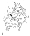
- FIG 4 is a rear perspective view of one embodiment of a fixture 100 of the present invention.
- the fixture 100 can use some of the components from the aforementioned fixture 50. Such components, however, are not relevant to the present invention and are not discussed.
- the fixture 100 includes a clamp assembly 101.
- Figure 5 is an exploded view of the clamp assembly 101.
- the clamp assembly 101 has two spindle arms assemblies 105, 107.
- Each spindle arm assembly has an arm 109, 111 and a rubber-tipped spindle 113, 115.
- the spindle 113, 115 preferably mounts to the arm 109, 111 in an adjustable fashion.
- the spindle 113, 115 has threads that engage corresponding threads in an opening 117, 119 in the arm 109, 111.
- the spindle 113, 115 can also include a lock washer 121, 123 and a jam nut 125, 127 to set the adjustability of the spindle 113, 115.
- the arms 109, 111 and spindles 113, 115 could be made from any suitable material, such as plastic (e.g. poly urea urethane RP6444) or stainless steel.
- the spindle arm assemblies 105, 107 mount to a body 129 through corresponding channels 131, 133.
- the body 129 can be made from any suitable material, such as glass-filled nylon or stainless steel.
- the body 129 is preferably a glass-filed nylon (e.g. DURAFORM GF available from 3D Systems of Valencia, California) formed by selective laser sintering (SLS).
- SLS selective laser sintering
- a pivot pin 135 extends through a passageway 137 in the main body 129 and through openings 139, 141 in the arms 109, 111. This allows the spindle arm assemblies 105, 107 to rotate relative to the main body 129.
- a set screw 143 retains the pivot pin 135 within the main body 129.
- the arms 109, 111 could have recesses at a medial location to receive wear pads 145, 147.
- the wear pads can be made from any suitable material, such as an acetal resin like DELRIN available from DuPont of Wilmington, Delaware.
- the wear pads 145, 147 prevent galling at the contact point between the two metallic components. If plastic components were used, the present invention could eliminate the wear pads 145.
- the clamp assembly 101 uses a single lever arm 151 to actuate both spindle arm assemblies 105, 107.
- the ratio between the force produced in the spindle arm assemblies 105, 107 by the operator-applied force to the lever arm 151 is approximately 9:1. Other ratios, however, are possible.
- the lever arm 151 can include a knob 153 threaded to a distal end. A proximal end of the lever arm 151 mounts to a cam 155. Preferably, the lever arm 151 extends into an opening 157 in the cam 155. A cross pin 159 extending into an opening 161 in the cam 155 and an opening 163 in the lever arm 151 secures the lever arm 151 to the cam 155.
- the cam 155 resides within an opening 165 in the main body 129.
- the opening 165 is sized so that the cam 155 can rotate therein. Rotation occurs when the operator O rotates the lever arm 151.
- the cam 155 includes shaped surfaces 167, 169 (shown in phantom) against which the wear pads 145, 147 of the spindle arm assemblies 105, 107 seat.
- Springs 171, 173 partially residing within openings in the arms 109, 111 and in the main body 131 urges the spindle arm assemblies 105, 107 against the cam 155.
- the present invention locates the spindle arm assemblies 105, 107 relative to the contact points 59 of the nest assembly so that the spindle arm assemblies 105, 107 urge the workpiece W towards each contact point 59.
- the specific location of the spindle arm assemblies 105, 107 relative to the contact points 59 necessary to achieve this positive placement feature could be determined using suitable vector analysis software or by other suitable methods.
- the clamp assembly 101 could be used on a variety of different EDM machines (not shown). Most of the clamp assembly 101 (i.e. the main body 129) could remain the same. The only non-universal components would be the spindle arm assemblies 105, 107. These assemblies 105, 107 would need to be specifically designed based upon the location of the contact points 59 on the EDM machine and the shape of the workpiece W placed in the machine. The designer would, however, shape each spindle arm assembly 105, 107 to fit into the universal main body 129.
- Figure 6a displays the fixture 100 in a disengaged configuration.
- the operator O can install the workpiece W into the nest assembly (only two contact points 175 of the nest assembly are shown).
- the operator O rotates the lever arm 151 along the engaging path E.
- the shaped surfaces 167, 169 of the cam 155 drive the spindle arm assemblies 105, 107 along the actuation path P towards the workpiece W.
- Figure 6b displays the fixture 100 in an engaged configuration.
- the workpiece is positively positioned against the contact points 175 of the nest assembly.
- the workpiece can undergo the EDM process.
- the operator O rotates the lever arm 151 along the release path R.
- the springs 171, 173 keep the spindle arm assemblies 105, 107 in contact with the cam 155.
- the present invention in its preferred embodiment at least provides numerous benefits.
- the single lever arm 151 allows operator actuation with only one hand.
- the conventional apparatus 10 requires two hands (one per toggle clamp).
- the lever arm 51 is larger than the aforementioned conventional lever arm 65, 67.
- the increased size serves as a force multiplier to operator input.
- the present invention can exhibit a 9:1 ratio of force input to force output.
- the operator can easily actuate the lever arm 151.
- the operator no longer has to overcome the force of the toggle clamps 53, 55.
- the operator O can readily observe or feel the larger lever arm 151 when reaching behind the fixture 100.
- the actuation path P of the spindle arm assemblies 105, 107 directs the workpiece W towards the contact points 175 of the nest assembly. This provides positive placement of the workpiece W in the nest assembly.
- the engaging path E is directed towards the front of the machine.
- this description focused on a workpiece fixture for EDM machines.
- the present invention could be used on any equipment that requires secure placement and location of a workpiece. Examples include milling machines, drills, grinders, saws, presses, gages and assembly fixtures.
Landscapes
- Engineering & Computer Science (AREA)
- Mechanical Engineering (AREA)
- Jigs For Machine Tools (AREA)
- Electrical Discharge Machining, Electrochemical Machining, And Combined Machining (AREA)
Claims (9)
- Dispositif de serrage (100) pour fixer une pièce de fabrication (W), comprenant :un socle (129) ;une pluralité de positionneurs (175) sur ledit socle pour accepter la pièce de fabrication ;une pluralité de bras (109, 111), chacun fixé de façon pivotante audit socle ; et caractérisé en ce qu'il comprend :un seul levier manuel (151) pour rotation par un opérateur pour actionner ladite pluralité de bras (109, 111) contre la pièce de fabrication (W) de telle sorte que lesdits bras positionnent fermement la pièce de fabrication contre ladite pluralité de positionneurs (175) ;ladite pluralité de bras (109, 111) étant agencée pour tourner vers la pièce de fabrication (W) dans une direction le long d'un chemin d'actionnement (P),ledit levier manuel (151) étant agencé pour tourner dans une direction le long d'un chemin d'engagement (E),lesdits bras et ledit levier tournant dans la même direction à la fois lors de l'engagement de la pièce de fabrication et lors de la libération de la pièce de fabrication.
- Dispositif de serrage (100) selon la revendication 1, dans lequel ladite pluralité de positionneurs (175) comprend six positionneurs.
- Dispositif de serrage (100) selon la revendication 1 ou 2, dans lequel ladite pluralité de bras (109, 111) comprend deux bras.
- Dispositif de serrage (100) selon l'une quelconque des revendications précédentes, le dispositif de serrage faisant partie d'un appareil d'usinage par décharge électrique.
- Dispositif de serrage (100) selon l'une quelconque des revendications précédentes, comprenant en outre une came (155), ledit levier (151) faisant tourner ladite came (155), et ladite came actionnant ladite pluralité de bras (109, 111).
- Appareil (10) d'usinage par décharge électrique (EDM), comprenant :une cuve (17) ;un support (13) pour soutenir une électrode dans ladite cuve (17) ; etun dispositif de serrage (100) selon l'une quelconque des revendications précédentes pour soutenir la pièce de fabrication (W) dans ladite cuve (17),dans lequel ledit levier (151) s'actionne vers l'avant de ladite cuve (17).
- Procédé de fixation d'une pièce de fabrication (W), comprenant les étapes consistant à :se procurer un dispositif de serrage (100) selon l'une quelconque des revendications 1 à 5 ;placer la pièce de fabrication (W) sur ladite pluralité de positionneurs (175) ; etactionner ledit levier (109, 111) pour entraîner ladite pluralité de bras (109, 111) contre la pièce de fabrication (W).
- Procédé selon la revendication 7, dans lequel ledit dispositif de serrage (100) fait partie d'un appareil d'usinage par décharge électrique.
- Procédé selon la revendication 7 ou 8, dans lequel ledit levier (151) se rapproche de l'avant du dispositif de serrage (100) au cours de l'étape d'actionnement.
Applications Claiming Priority (2)
| Application Number | Priority Date | Filing Date | Title |
|---|---|---|---|
| US60764 | 2002-01-30 | ||
| US10/060,764 US6627833B2 (en) | 2002-01-30 | 2002-01-30 | Fixture for securing a workpiece |
Publications (3)
| Publication Number | Publication Date |
|---|---|
| EP1338367A2 EP1338367A2 (fr) | 2003-08-27 |
| EP1338367A3 EP1338367A3 (fr) | 2005-04-13 |
| EP1338367B1 true EP1338367B1 (fr) | 2011-07-06 |
Family
ID=27610089
Family Applications (1)
| Application Number | Title | Priority Date | Filing Date |
|---|---|---|---|
| EP03250561A Expired - Lifetime EP1338367B1 (fr) | 2002-01-30 | 2003-01-30 | Dispositif de fixation d'une pièce de travail |
Country Status (3)
| Country | Link |
|---|---|
| US (1) | US6627833B2 (fr) |
| EP (1) | EP1338367B1 (fr) |
| JP (1) | JP2003236728A (fr) |
Families Citing this family (16)
| Publication number | Priority date | Publication date | Assignee | Title |
|---|---|---|---|---|
| US6844518B1 (en) * | 2003-12-22 | 2005-01-18 | United Technologies Corporation | Hole-drilling guide and method |
| US7377037B2 (en) * | 2004-05-25 | 2008-05-27 | General Electric Company | Fillet machining method without adaptive probing |
| US7334306B2 (en) * | 2004-06-02 | 2008-02-26 | General Electric Company | Methods and apparatus for fabricating a turbine nozzle assembly |
| US7883320B2 (en) * | 2005-01-24 | 2011-02-08 | United Technologies Corporation | Article having diffuser holes and method of making same |
| US20070151954A1 (en) * | 2006-01-05 | 2007-07-05 | General Electric Company | Methods and apparatus for fabricating components |
| US8151458B2 (en) * | 2008-02-21 | 2012-04-10 | United Technologies Corporation | Non-metallic cover for a fixture |
| SG159412A1 (en) * | 2008-08-25 | 2010-03-30 | Pratt & Whitney Services Pte L | Fixture for compressor stator chord restoration repair |
| US9687926B2 (en) * | 2009-04-03 | 2017-06-27 | United Technologies Corporation | Trailing edge machining of a workpiece |
| US8616077B2 (en) * | 2009-08-05 | 2013-12-31 | United Technologies Corporation | Non-destructive inspection method for metallic alloys |
| US9193111B2 (en) | 2012-07-02 | 2015-11-24 | United Technologies Corporation | Super polish masking of integrally bladed rotor |
| US20140003923A1 (en) | 2012-07-02 | 2014-01-02 | Peter Finnigan | Functionally graded composite fan containment case |
| JP6875238B2 (ja) * | 2017-09-15 | 2021-05-19 | 三菱パワー株式会社 | 貼付治具及び動翼の製造方法 |
| US11014179B2 (en) | 2018-03-15 | 2021-05-25 | Delavan Inc. | Fixtures for additively manufactured workpieces |
| CN108402617A (zh) * | 2018-05-14 | 2018-08-17 | 深圳市鑫万福珠宝首饰有限公司 | 一种防夹伤的珠宝加工用夹具 |
| US20250381607A1 (en) * | 2024-06-14 | 2025-12-18 | Chromalloy Gas Turbine Llc | Multi-station edm for vanes |
| US20260033479A1 (en) * | 2024-08-04 | 2026-02-05 | Vasile OROS | Hand-Held Rodent Trap Setting Device |
Family Cites Families (15)
| Publication number | Priority date | Publication date | Assignee | Title |
|---|---|---|---|---|
| US1350097A (en) * | 1919-04-08 | 1920-08-17 | Frank B Glover | Work-holder |
| US2788687A (en) * | 1954-12-08 | 1957-04-16 | George W Ridge | Pivotal-jaw vise having fulcrum and cam independently adjustable |
| US3331166A (en) * | 1964-11-27 | 1967-07-18 | Brenning Albert | Jig for grinding turbine blades of jet engines |
| CH550633A (fr) * | 1972-09-18 | 1974-06-28 | Genevoise Instr Physique | Table pour machine d'electro-erosion. |
| US3827965A (en) * | 1973-02-02 | 1974-08-06 | United Aircraft Corp | Electrochemical drilling apparatus |
| US4463241A (en) | 1982-06-28 | 1984-07-31 | General Electric Company | Fixture for electrode wire EDM apparatus |
| JPS61257720A (ja) * | 1985-05-13 | 1986-11-15 | Inoue Japax Res Inc | 電気加工装置用被加工体取付装置 |
| US4638602A (en) * | 1986-01-03 | 1987-01-27 | Cavalieri Dominic A | Turbine blade holding device |
| FR2661347B1 (fr) * | 1990-04-27 | 1995-05-19 | Aerospatiale | Pince pour presser une piece sur un support. |
| JPH09225750A (ja) * | 1996-02-19 | 1997-09-02 | Hoden Seimitsu Kako Kenkyusho Ltd | 放電加工方法およびその装置 |
| US5847350A (en) | 1997-06-16 | 1998-12-08 | General Electric Company | Adjustable mount |
| US6068541A (en) * | 1997-12-22 | 2000-05-30 | United Technologies Corporation | Method for using a fixture enabling more accurate machining of a part |
| DE29901363U1 (de) * | 1999-01-27 | 1999-05-06 | Festo AG & Co, 73734 Esslingen | Kniehebel-Spannvorrichtung |
| US6326576B1 (en) | 1999-09-22 | 2001-12-04 | General Electric Company | Method and apparatus for electrical discharge machining |
| US6560890B1 (en) * | 2002-02-21 | 2003-05-13 | General Electric Company | Fixture for locating and clamping a part for laser drilling |
-
2002
- 2002-01-30 US US10/060,764 patent/US6627833B2/en not_active Expired - Fee Related
-
2003
- 2003-01-30 EP EP03250561A patent/EP1338367B1/fr not_active Expired - Lifetime
- 2003-01-30 JP JP2003021806A patent/JP2003236728A/ja active Pending
Also Published As
| Publication number | Publication date |
|---|---|
| EP1338367A3 (fr) | 2005-04-13 |
| EP1338367A2 (fr) | 2003-08-27 |
| US6627833B2 (en) | 2003-09-30 |
| JP2003236728A (ja) | 2003-08-26 |
| US20030141284A1 (en) | 2003-07-31 |
Similar Documents
| Publication | Publication Date | Title |
|---|---|---|
| US6627833B2 (en) | Fixture for securing a workpiece | |
| US6786478B2 (en) | Locating assembly having an extendable clamping finger | |
| JP3725129B2 (ja) | ロボット用ツール先端部材自動交換装置 | |
| US4294013A (en) | Portable hacksaw | |
| US7931054B2 (en) | Modular router with secondary release lever | |
| US20100005637A1 (en) | Turbine Element Repair Fixture | |
| US8408259B2 (en) | Modular router with base power switch | |
| WO2004018154A1 (fr) | Dispositif de serrage | |
| WO1999055481A1 (fr) | Outil electrique rotatif dote d'un mandrin actionne a distance | |
| US5847350A (en) | Adjustable mount | |
| CN101668607A (zh) | 刀片可移动的移动式手动切割机 | |
| US8607833B2 (en) | Router depth adjustment mechanism | |
| CN107530899B (zh) | 带有垂臂轨道托架的电动工具 | |
| US8066041B2 (en) | Modular router with motor clamp | |
| CN113195136B (zh) | 镗孔刀具 | |
| CN107567363B (zh) | 带有被保护的耦合板的电动工具 | |
| JP5406497B2 (ja) | 切削装置 | |
| US4815202A (en) | Electronic component insertion machine | |
| US4766282A (en) | Fusing apparatus and method with electrode changing | |
| CN210412905U (zh) | 一种回丝工装 | |
| JP5512946B2 (ja) | 切削装置 | |
| WO2005009659A1 (fr) | Mandrin excentrique | |
| KR0177625B1 (ko) | Cnc 선반의 서브 스핀들에 설치된 공작물 배출장치 | |
| GB2408709A (en) | Hand-held machine tool having a threaded clamping means | |
| CN222843564U (zh) | 一种用于数控机床的异形件夹持工件 |
Legal Events
| Date | Code | Title | Description |
|---|---|---|---|
| PUAI | Public reference made under article 153(3) epc to a published international application that has entered the european phase |
Free format text: ORIGINAL CODE: 0009012 |
|
| AK | Designated contracting states |
Designated state(s): AT BE BG CH CY CZ DE DK EE ES FI FR GB GR HU IE IT LI LU MC NL PT SE SI SK TR |
|
| AX | Request for extension of the european patent |
Extension state: AL LT LV MK RO |
|
| PUAL | Search report despatched |
Free format text: ORIGINAL CODE: 0009013 |
|
| AK | Designated contracting states |
Kind code of ref document: A3 Designated state(s): AT BE BG CH CY CZ DE DK EE ES FI FR GB GR HU IE IT LI LU MC NL PT SE SI SK TR |
|
| AX | Request for extension of the european patent |
Extension state: AL LT LV MK RO |
|
| 17P | Request for examination filed |
Effective date: 20051005 |
|
| AKX | Designation fees paid |
Designated state(s): DE FR GB IT |
|
| 17Q | First examination report despatched |
Effective date: 20070216 |
|
| GRAP | Despatch of communication of intention to grant a patent |
Free format text: ORIGINAL CODE: EPIDOSNIGR1 |
|
| GRAS | Grant fee paid |
Free format text: ORIGINAL CODE: EPIDOSNIGR3 |
|
| GRAA | (expected) grant |
Free format text: ORIGINAL CODE: 0009210 |
|
| AK | Designated contracting states |
Kind code of ref document: B1 Designated state(s): DE FR GB IT |
|
| REG | Reference to a national code |
Ref country code: GB Ref legal event code: FG4D |
|
| REG | Reference to a national code |
Ref country code: DE Ref legal event code: R096 Ref document number: 60337615 Country of ref document: DE Effective date: 20110908 |
|
| PLBE | No opposition filed within time limit |
Free format text: ORIGINAL CODE: 0009261 |
|
| STAA | Information on the status of an ep patent application or granted ep patent |
Free format text: STATUS: NO OPPOSITION FILED WITHIN TIME LIMIT |
|
| PG25 | Lapsed in a contracting state [announced via postgrant information from national office to epo] |
Ref country code: IT Free format text: LAPSE BECAUSE OF FAILURE TO SUBMIT A TRANSLATION OF THE DESCRIPTION OR TO PAY THE FEE WITHIN THE PRESCRIBED TIME-LIMIT Effective date: 20110706 |
|
| 26N | No opposition filed |
Effective date: 20120411 |
|
| REG | Reference to a national code |
Ref country code: DE Ref legal event code: R097 Ref document number: 60337615 Country of ref document: DE Effective date: 20120411 |
|
| REG | Reference to a national code |
Ref country code: FR Ref legal event code: ST Effective date: 20120928 |
|
| PG25 | Lapsed in a contracting state [announced via postgrant information from national office to epo] |
Ref country code: FR Free format text: LAPSE BECAUSE OF NON-PAYMENT OF DUE FEES Effective date: 20120131 |
|
| PGFP | Annual fee paid to national office [announced via postgrant information from national office to epo] |
Ref country code: GB Payment date: 20130130 Year of fee payment: 11 Ref country code: DE Payment date: 20130123 Year of fee payment: 11 |
|
| REG | Reference to a national code |
Ref country code: DE Ref legal event code: R119 Ref document number: 60337615 Country of ref document: DE |
|
| GBPC | Gb: european patent ceased through non-payment of renewal fee |
Effective date: 20140130 |
|
| REG | Reference to a national code |
Ref country code: DE Ref legal event code: R119 Ref document number: 60337615 Country of ref document: DE Effective date: 20140801 |
|
| PG25 | Lapsed in a contracting state [announced via postgrant information from national office to epo] |
Ref country code: DE Free format text: LAPSE BECAUSE OF NON-PAYMENT OF DUE FEES Effective date: 20140801 |
|
| PG25 | Lapsed in a contracting state [announced via postgrant information from national office to epo] |
Ref country code: GB Free format text: LAPSE BECAUSE OF NON-PAYMENT OF DUE FEES Effective date: 20140130 |