EP1338497A1 - Dispositif de détection de position pour la béquille latérale d'une motocyclette - Google Patents
Dispositif de détection de position pour la béquille latérale d'une motocyclette Download PDFInfo
- Publication number
- EP1338497A1 EP1338497A1 EP03004265A EP03004265A EP1338497A1 EP 1338497 A1 EP1338497 A1 EP 1338497A1 EP 03004265 A EP03004265 A EP 03004265A EP 03004265 A EP03004265 A EP 03004265A EP 1338497 A1 EP1338497 A1 EP 1338497A1
- Authority
- EP
- European Patent Office
- Prior art keywords
- side stand
- detecting device
- position detecting
- stand
- motorcycle
- Prior art date
- Legal status (The legal status is an assumption and is not a legal conclusion. Google has not performed a legal analysis and makes no representation as to the accuracy of the status listed.)
- Granted
Links
- 230000008878 coupling Effects 0.000 claims description 15
- 238000010168 coupling process Methods 0.000 claims description 15
- 238000005859 coupling reaction Methods 0.000 claims description 15
- 239000011347 resin Substances 0.000 description 3
- 229920005989 resin Polymers 0.000 description 3
- 238000010276 construction Methods 0.000 description 2
- XLYOFNOQVPJJNP-UHFFFAOYSA-N water Substances O XLYOFNOQVPJJNP-UHFFFAOYSA-N 0.000 description 2
- 238000010586 diagram Methods 0.000 description 1
- 239000000428 dust Substances 0.000 description 1
- 238000009499 grossing Methods 0.000 description 1
- 238000000034 method Methods 0.000 description 1
- 239000000758 substrate Substances 0.000 description 1
Images


Classifications
-
- B—PERFORMING OPERATIONS; TRANSPORTING
- B62—LAND VEHICLES FOR TRAVELLING OTHERWISE THAN ON RAILS
- B62H—CYCLE STANDS; SUPPORTS OR HOLDERS FOR PARKING OR STORING CYCLES; APPLIANCES PREVENTING OR INDICATING UNAUTHORIZED USE OR THEFT OF CYCLES; LOCKS INTEGRAL WITH CYCLES; DEVICES FOR LEARNING TO RIDE CYCLES
- B62H1/00—Supports or stands forming part of or attached to cycles
- B62H1/02—Articulated stands, e.g. in the shape of hinged arms
Definitions
- the present invention relates to a position detecting device for a side stand for detecting whether the side stand, which rotates between a storage position and a stand position around a supporting shaft attached to the one side of a motorcycle, is located at either the storage position or the stand position, thereby preventing the motorcycle from being run while the side stand is being located at the stand position.
- the side stand for a motorcycle is attached to the motorcycle so as to be rotatable between a stand position, where the tip of the side stand is in contact with the ground so that the motorcycle is supported in an upright state, and a storage position, where the tip of the side stand is separated from the ground so that the side stand is housed in the motorcycle.
- a stand position where the tip of the side stand is in contact with the ground so that the motorcycle is supported in an upright state
- a storage position where the tip of the side stand is separated from the ground so that the side stand is housed in the motorcycle.
- JP-A-2-7314 discloses a technique for detecting whether the side stand is located at the stand position or the storage position, thereby calling attention to a driver.
- the position detecting device for a side stand disclosed in the above publication is provided with a cam face formed on the base side of the side stand and a plunger which is in contact with the came face and slides with a rotating operation of the side stand.
- the position of the side stand is detected by switching a contact which is connected or disconnected by the sliding operation of the plunger.
- the above position detecting device for a side stand presented a problem that since the cam face used to slide the plunger is formed on the side of the base of the side stand, accident error of combining the side stand and plunger with a vehicle lowers the detecting accuracy of the position of the side stand. Specifically, since the cam and plunger in the above detecting device are individually combined with the vehicle as individual components, accident error in each combining operation may make it impossible to carry out a desired operation of the plunger with the rotation of the side stand and hence may lower the detecting accuracy.
- the position detecting device is newly built into the conventional vehicle which does not detect the position of the side stand, not only the position detecting device must be installed, but also the cam face must be newly formed on the side of the base. This increases cost taken for new set-up of a device. Further, since a contact portionbetween the cam face and the plunger tip is exposed externally, the foreign matter such as dust may invade the contact portion, and hence the detecting accuracy may be lowered.
- the present invention has been accomplished in view of such a circumstance, and intends to provide a position detecting device for a side stand which can improve the detecting accuracy of the position of the side stand and suppress cost taken for new set-up of a device.
- the present invention described in a first aspect is a position detecting device for a side stand for detecting whether the side stand, which rotates between a storage position and a stand position around a supporting shaft attached to a bracket of a motorcycle, is located at either the storage position or the stand position, having a position detecting device body fixed to the supporting shaft, a cam member with a cam face formed partially thereof accommodated within the position detecting device body and rotated together with the side stand, a plunger arranged within the position detecting device body and having a tip in contact with the cam face of the cam member, the plunger sliding as the cam member rotates, a fixed contact fixed within the position detecting device body, and a movable contact which connects to or disconnects from the fixed contact by a sliding operation of the plunger, characterized in that the position of the side stand is detected on the basis of the connecting state between the movable contact and the fixed contact.
- the cam member also rotates so that the plunger with the tip in contact with the cam face slides.
- the fixed contact and movable contact which have been separated from each other are connected to each other. Therefore, the position of the side stand (either the storage position or the stand position) can be detected.
- the present invention described in a second aspect is characterized in that the cam member is formed of a cylindrical member, and attached to the supporting shaft so as to protrude toward the side of the motorcycle thereby forming a protruding portion which has a small diameter portion with the cam face.
- the present invention described in a third aspect is characterized in that the cam member has a coupling plate protruding toward the side stand, and the coupling plate is fit into a hole made at a prescribed position of the side stand so that the cam member is coupled with the side stand.
- the present invention is a motorcycle comprising the position detecting device for the side stand according to anyone of the first to third aspects of the present invention, wherein the position detecting device for the side stand is electrically connected to an engine of the motorcycle so as to control the engine.
- the motorcycle according to the above construction wherein, unless the storage position of the side stand is detected, the engine is prevented from permitting to start.
- the motorcycle according to the above construction wherein, where the engine is started with the side stand being located at the stand position, a warning light arranged on an indicator is lit, or warning sound is generated by a buzzer so that the attention of a driver is attracted.
- the position detecting device for a side stand serves to detect whether the side stand, which rotates between a storage position and a stand position around a supporting shaft attached to the one side of a motorcycle, is located at either the storage position or the stand position, thereby preventing the motorcycle from being run while the side stand is being located at the stand position.
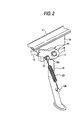
- a body frame F of a motorcycle is provided with a bracket 19 for attaching a side stand 18.
- the bracket 19 has an attachment hole 19a and a boss 19b.
- An attachment 18a formed at a base end of the side stand 18 is fit to the bracket 18, and a hole 18aa formed in the attachment 18a is mated with the attachment hole 19a. Thereafter, a fixing bolt 20 is passed through these hole 18aa and the attachment hole 19a.
- the tip side of the fixing bolt 20 is engaged with a nut 21 from an opposite side of the bracket 19.
- the side stand 18 is adapted to rotate between a stand position and a storage position around the fixing bolt 20.
- a boss 18b is formed on the side of the side stand 18.
- a return spring 23 is suspendedbetween the boss 18b and a boss 19b formed on the bracket 19 to elastically hold the side stand at the stand position or the storage position.
- a screw hole 20a having an internal thread on the internal face is formed at the head of the fixing bolt 20, a screw hole 20a having an internal thread on the internal face is formed.
- An attaching thread 17 is threaded through the screw hole 20a with a position detecting device 24 (including a color 9) according to this embodiment being located therebetween .
- the position detecting device 24 is fixed in the vicinity of the fixing bolt 20 of the bracket 19 so that the position of the side stand 18 is detected.
- the attaching thread 17 since the attaching thread 17 is secured to the fixing bolt 20 which serves as a supporting shaft of the side stand 18, when the fixing bolt 20 rotates together with the side stand 18, the attaching thread 17 also rotates.
- the position detecting device 24 mainly includes a position detecting device body 1, a cam member 2 and a case 4 having a plunger 8.
- the position detecting device 24 is fixed to the bracket 19 of the motorcycle.
- the position detecting device body 1 which is a resin molded component, serves as a box for the position detecting device 24.
- the position detecting device body 1 has a first accommodating space 1b for accommodating the cam member 2 and a second accommodating space 1c for accommodating the plunger 8, contacts (fixed contacts 7a and movable contact 5 described later), etc.
- the first accommodating space 1b is a concave space which is opened toward the side stand 18 (Fig. 3).
- the second accommodating space 1c is a space in which a grommet 12 is pressed in an opening 1ca opened at the end of the position detecting device body 1.
- reference numeral 16 denotes a spring pin.
- the grommet 12 is pressed in the opening 1ca to seal the second accommodating space 1c.
- the grommet 12 serves to prevent water or a foreign matter from invading from the opening 1c and secures the case 4 at a prescribed position within the second accommodating space 1c.
- a coupling hole ld is formed for coupling these accommodating spaces. The plunger is passed through the coupling hole 1d.
- the cam member 2 which is formed of a cylindrical member made of resin, is arranged to be rotatable in the position detecting device body 1. Specifically, at the center of the cam member 2, a hole 2b is vertically made so as to pass through the cammember 2. An attaching thread is threaded into the hole 2b through a color 9.
- the above cam member 2 protrudes from the fixing bolt 20 toward the side of the motorcycle.
- a part of the side of the protruding portion having a small diameter is served as a cam face 2a.
- the portion (fixing bolt 20) which rotates with the side stand 18 is protruded to extend toward the motorcycle by the height of the cam member 2, and the tip of the plunger 8 is kept in contact with the cam face 2a formed in the protruding portion.
- the plunger 8 can be offset toward the side of the motorcycle (width direction of the vehicle) thereby reducing the installing distance of the position detecting device 24 in the longitudinal direction. Specifically, since the plunger 8 is offset, the installing distance of the position detecting device 24 is increased in the width direction of the vehicle. However, since the tip of the plunger 8 is kept in contact with the cam face 2a which is a small diameter portion of the cam member 2, the installing distance of the position detecting device 24 can be reduced.
- the cam member 2 has a coupling plate 6 which protrudes toward the side stand 18 at the edge of the surface of the cam.
- the coupling plate 6 is fit into a hole made at a prescribed position of the side stand 18 so that the cam member 2 is coupled with the side stand 18. Therefore, the rotating operation of the side stand 18 is transmitted to the cam member 2 via the coupling plate 6 so that the cam member 2 can be rotated together with the side stand 18.
- the coupling plate 6 is arranged in a predetermined positional relationship with the cam face 2a, when the coupling plate 6 is fit in the hole 18c, the cam face 2a can be oriented in a prescribed direction. Therefore, the initial positions of the cam face 2a and the plunger 8 can be easily set. This further improves the detecting accuracy of the position of the side stand 18.
- reference numeral 22 denotes a smoothing member 22 on the surface of which the cam member 2 can smoothly slide.
- reference numerals 14 and 15 denote an O-ring, respectively, which serve to prevent the water or foreign matter, which has invaded the first accommodating space 1b from a gap between the cam member 2 and position detecting device body 1, from invading the side of the plunger 8 (side of the second accommodating space 1c).
- the plunger 8 is arranged within a resin case 4 accommodated in the second accommodating space 1c of the position detecting body 1.
- the tip of the plunger 8 is in contact with the cam face 2a and slides with the rotation of the cammember 2. More specifically, as seen from Figs. 4 and 5, a roller 3 which is slidable in a longitudinal direction is arranged in the case 4.
- the plunger 8 is attached to the one end of the roller 3, and a spring 10 is attached to the other end of the roller 3.
- the spring 10 is suspended between the other end of the roller 3 and the case 4.
- the roller 3 is always urged toward the cam member 2 so that the tip of the plunger 8 can be kept in contact with the cam face 2a. Specifically, since the plunger 8 is always pressed on the cam face 2a, when the cam member 2 rotates, the plunger 8 moves in or out from the case 4 along the profile of the cam face 2a, and thereby the roller 3 is slid in the longitudinal direction of the case 4. Incidentally, an oil seal 8 is arranged on the outer surface to carry out the sliding operation of the plunger 8 smoothly.
- a substrate 7 having fixed contacts 7a is arranged within the case 4, whereas the roller 3 has a movable contact 5 so as to be opposite to the fixed contacts 7a. Therefore, by the sliding operation of the plunger 8 and the roller 3, the movable contact 5 is connected with or disconnected from the fixed contacts 7a.
- the connecting state is transmitted to an ECU loaded on the motorcycle through codes 11.
- the position detecting device 24 is mechanically coupled with the side stand 18 and also electrically coupled with the ECU through the cords 11.
- the movable contact 5 is connected with the fixed contacts 7a, an electric signal flows through the ECU so that the position of the side stand 18 can be recognized.
- the codes 11 are extended to the ECU through through-holes formed in the. grommet 12.
- the ECU is electrically connected to an engine of the motorcycle so that it can control the engine. Therefore, the ECU can be designed so that unless it is detected that the side stand 18 is at the storage position, the engine is not permitted to start.
- a warning light arranged on an indicator may be lit, or otherwise warning sound may be generated by a buzzer so that the attention of a driver is attracted.
- both the cam member 2 and the plunger 8 are arranged within the position detecting device body 1, when they are built into the vehicle, the combination error between the cam member 2 and the plunger 8 can be prevented from being produced, thereby improving the detecting accuracy for the position of the side stand 18. Further, since the cam member 2 is independent of the side stand 18 and also accommodated within the position detecting device body 1, this embodiment can be easily applied to the side stand 18 not having the cam face 2a, thereby suppressing the cost for new set-up of a device.
- the present invention should not be limited to this embodiment.
- the cam may be made in a different shape.
- the movable contact when the side stand 18 is located at the storage position, the movable contact is connected to the fixed contacts. However, when the side stand 18 is located at the stand position, the movable contact may be connected to the fixed contacts so that it is detected that the side stand is located at either position by detecting the stand position.
- the storage position and stand position of the side stand is detected using a simple ON-OFF circuit.
- these storage position and stand position may be detected by any other various means (e.g. a selector switch).
- both the cam member and the plunger are arranged within the position detecting device body, when they are built into the vehicle, the combination error between the cam member and the plunger can be prevented from being produced, thereby improving the detecting accuracy for the position of the side stand.
- the cam member is independent of the side stand and also accommodated within the position detecting device body, the present invention can be easily applied to the side stand not having the cam face, thereby suppressing the cost taken for new set-up of a device.
- the plunger can be offset toward the side of the motorcycle (width direction of the vehicle) thereby reducing the installing distance of the position detecting device in the longitudinal direction (direction of extending the plunger).
- the cam member is provided with a coupling plate, and the coupling plate is fit into a hole of the side stand so that the cam member is coupled with the side stand. Therefore, the rotating operation of the side stand can be transmitted to the cam member through the coupling plate, and the initial positions of the cam member and the plunger can be easily set. This further improves the detecting accuracy of the position of the side stand.
Landscapes
- Engineering & Computer Science (AREA)
- Mechanical Engineering (AREA)
- Rotary Switch, Piano Key Switch, And Lever Switch (AREA)
- Length Measuring Devices With Unspecified Measuring Means (AREA)
- A Measuring Device Byusing Mechanical Method (AREA)
Applications Claiming Priority (2)
| Application Number | Priority Date | Filing Date | Title |
|---|---|---|---|
| JP2002049758A JP3976239B2 (ja) | 2002-02-26 | 2002-02-26 | サイドスタンドの位置検出装置 |
| JP2002049758 | 2002-02-26 |
Publications (2)
| Publication Number | Publication Date |
|---|---|
| EP1338497A1 true EP1338497A1 (fr) | 2003-08-27 |
| EP1338497B1 EP1338497B1 (fr) | 2005-01-19 |
Family
ID=27655484
Family Applications (1)
| Application Number | Title | Priority Date | Filing Date |
|---|---|---|---|
| EP20030004265 Expired - Lifetime EP1338497B1 (fr) | 2002-02-26 | 2003-02-26 | Dispositif de détection de position pour la béquille latérale d'une motocyclette |
Country Status (4)
| Country | Link |
|---|---|
| EP (1) | EP1338497B1 (fr) |
| JP (1) | JP3976239B2 (fr) |
| DE (1) | DE60300268T2 (fr) |
| ES (1) | ES2231740T3 (fr) |
Cited By (4)
| Publication number | Priority date | Publication date | Assignee | Title |
|---|---|---|---|---|
| US7631885B2 (en) | 2007-04-16 | 2009-12-15 | Harley-Davidson Motor Company Group, LLC | Intelligent interlock for a motorcycle stand |
| CN101875376A (zh) * | 2009-04-30 | 2010-11-03 | 阿尔卑斯电气株式会社 | 侧支架开关和侧支架装置 |
| WO2017124271A1 (fr) * | 2016-01-18 | 2017-07-27 | 刘建兵 | Procédé de transmission d'informations pendant une détection de béquille et moto |
| FR3103756A1 (fr) * | 2019-12-01 | 2021-06-04 | jean luc bordel mathiolon | Dispositif d’eclairage automatique pour bequille de vehicule a deux roues |
Families Citing this family (8)
| Publication number | Priority date | Publication date | Assignee | Title |
|---|---|---|---|---|
| ES2279706B1 (es) * | 2005-11-10 | 2009-03-16 | Leo Leonelli Selles | Dispositivo para detectar la posicion del caballete en vehiculos de dos ruedas. |
| JP5729867B2 (ja) * | 2010-09-14 | 2015-06-03 | 本田技研工業株式会社 | 鞍乗型車両の出力制御装置 |
| JP5686788B2 (ja) * | 2012-12-17 | 2015-03-18 | オムロンオートモーティブエレクトロニクス株式会社 | 位置検出スイッチ及び回転スイッチ |
| CN104870299B (zh) * | 2013-01-10 | 2017-06-16 | 阿尔卑斯电气株式会社 | 侧支架的位置检测装置 |
| JP6501345B2 (ja) * | 2014-12-09 | 2019-04-17 | 朝日電装株式会社 | サイドスタンドの位置検出装置 |
| JP6501346B2 (ja) * | 2014-12-09 | 2019-04-17 | 朝日電装株式会社 | サイドスタンドの位置検出装置 |
| CN110023180B (zh) * | 2016-12-28 | 2021-03-09 | 阿尔卑斯阿尔派株式会社 | 支架的位置检测装置 |
| JP7253945B2 (ja) * | 2019-03-20 | 2023-04-07 | アルプスアルパイン株式会社 | サイドスタンドスイッチおよびサイドスタンド装置 |
Citations (6)
| Publication number | Priority date | Publication date | Assignee | Title |
|---|---|---|---|---|
| US4016538A (en) * | 1975-02-24 | 1977-04-05 | Miller Marion Z | Safety device for a motorcycle |
| US4883284A (en) * | 1987-12-25 | 1989-11-28 | Honda Giken Kogyo Kabushiki Kaisha | Position detecting device for a motorcycle side stand |
| JPH027314A (ja) * | 1988-06-27 | 1990-01-11 | Asahi Denso Kk | スイッチ |
| DE10002731A1 (de) * | 2000-01-22 | 2001-08-02 | A B Elektronik Gmbh | Stellungssensorschalter |
| JP2001270481A (ja) * | 2000-03-24 | 2001-10-02 | Denso Corp | 自動二輪車の制御装置 |
| EP1264760A1 (fr) * | 2001-01-19 | 2002-12-11 | Honda Giken Kogyo Kabushiki Kaisha | Dispositif de bequille pour moto |
-
2002
- 2002-02-26 JP JP2002049758A patent/JP3976239B2/ja not_active Expired - Fee Related
-
2003
- 2003-02-26 DE DE2003600268 patent/DE60300268T2/de not_active Expired - Lifetime
- 2003-02-26 EP EP20030004265 patent/EP1338497B1/fr not_active Expired - Lifetime
- 2003-02-26 ES ES03004265T patent/ES2231740T3/es not_active Expired - Lifetime
Patent Citations (6)
| Publication number | Priority date | Publication date | Assignee | Title |
|---|---|---|---|---|
| US4016538A (en) * | 1975-02-24 | 1977-04-05 | Miller Marion Z | Safety device for a motorcycle |
| US4883284A (en) * | 1987-12-25 | 1989-11-28 | Honda Giken Kogyo Kabushiki Kaisha | Position detecting device for a motorcycle side stand |
| JPH027314A (ja) * | 1988-06-27 | 1990-01-11 | Asahi Denso Kk | スイッチ |
| DE10002731A1 (de) * | 2000-01-22 | 2001-08-02 | A B Elektronik Gmbh | Stellungssensorschalter |
| JP2001270481A (ja) * | 2000-03-24 | 2001-10-02 | Denso Corp | 自動二輪車の制御装置 |
| EP1264760A1 (fr) * | 2001-01-19 | 2002-12-11 | Honda Giken Kogyo Kabushiki Kaisha | Dispositif de bequille pour moto |
Non-Patent Citations (2)
| Title |
|---|
| PATENT ABSTRACTS OF JAPAN vol. 014, no. 142 (E - 0904) 16 March 1990 (1990-03-16) * |
| PATENT ABSTRACTS OF JAPAN vol. 2002, no. 02 2 April 2002 (2002-04-02) * |
Cited By (4)
| Publication number | Priority date | Publication date | Assignee | Title |
|---|---|---|---|---|
| US7631885B2 (en) | 2007-04-16 | 2009-12-15 | Harley-Davidson Motor Company Group, LLC | Intelligent interlock for a motorcycle stand |
| CN101875376A (zh) * | 2009-04-30 | 2010-11-03 | 阿尔卑斯电气株式会社 | 侧支架开关和侧支架装置 |
| WO2017124271A1 (fr) * | 2016-01-18 | 2017-07-27 | 刘建兵 | Procédé de transmission d'informations pendant une détection de béquille et moto |
| FR3103756A1 (fr) * | 2019-12-01 | 2021-06-04 | jean luc bordel mathiolon | Dispositif d’eclairage automatique pour bequille de vehicule a deux roues |
Also Published As
| Publication number | Publication date |
|---|---|
| JP3976239B2 (ja) | 2007-09-12 |
| DE60300268T2 (de) | 2005-06-23 |
| ES2231740T3 (es) | 2005-05-16 |
| DE60300268D1 (de) | 2005-02-24 |
| EP1338497B1 (fr) | 2005-01-19 |
| JP2003252264A (ja) | 2003-09-10 |
Similar Documents
| Publication | Publication Date | Title |
|---|---|---|
| EP1338497B1 (fr) | Dispositif de détection de position pour la béquille latérale d'une motocyclette | |
| US7921684B2 (en) | Magnet-holding structure for magnetic position detector and steering lock apparatus | |
| US4883284A (en) | Position detecting device for a motorcycle side stand | |
| US5780796A (en) | Mounting construction of a combination switch | |
| US8616081B2 (en) | Shift lever device | |
| JP4456431B2 (ja) | ステアリングロック装置 | |
| JPH0631038B2 (ja) | 自動二輪車のサイドスタンド | |
| US20130319164A1 (en) | Electric steering lock device | |
| KR20150003672A (ko) | 전동 스티어링 록 장치 | |
| US20040208014A1 (en) | Mounting base for a warning light | |
| JPH08273465A (ja) | グロメットおよび該グロメットの検査装置 | |
| US20230282430A1 (en) | Switch assembly for a vehicle | |
| EP1036713A2 (fr) | Connecteur rotatif capable de facilement et fiablement reverrouiller un boitier mobile en position de rotation neutre après un test de rotation | |
| JP2001167858A (ja) | 回転コネクタ装置 | |
| CN212290145U (zh) | 一种平衡车用中壳及其平衡车 | |
| US6220732B1 (en) | Side marker lamp mounting assembly | |
| CN212709806U (zh) | 一种上壳体组件及其平衡车 | |
| JP3392519B2 (ja) | オイルレベルセンサ | |
| KR970004738B1 (ko) | 자동차의 스톱램프 스위치 부착구조 | |
| EP0198947A1 (fr) | Système pour contrôler des niveaux de liquide pour véhicules automobiles | |
| JP3693811B2 (ja) | コンビスイッチ | |
| CN219740496U (zh) | 车载监控装置及车辆 | |
| JP2586051Y2 (ja) | 車両用ターンシグナルスイッチの構造 | |
| CN216121606U (zh) | 一种线束固定卡防旋转结构 | |
| KR100373506B1 (ko) | 자동차 키 삽입 알림 장치의 마운팅 구조 |
Legal Events
| Date | Code | Title | Description |
|---|---|---|---|
| PUAI | Public reference made under article 153(3) epc to a published international application that has entered the european phase |
Free format text: ORIGINAL CODE: 0009012 |
|
| AK | Designated contracting states |
Designated state(s): AT BE BG CH CY CZ DE DK EE ES FI FR GB GR HU IE IT LI LU MC NL PT SE SI SK TR |
|
| AX | Request for extension of the european patent |
Extension state: AL LT LV MK RO |
|
| 17P | Request for examination filed |
Effective date: 20031204 |
|
| 17Q | First examination report despatched |
Effective date: 20031230 |
|
| AKX | Designation fees paid |
Designated state(s): DE ES GB IT |
|
| GRAP | Despatch of communication of intention to grant a patent |
Free format text: ORIGINAL CODE: EPIDOSNIGR1 |
|
| GRAA | (expected) grant |
Free format text: ORIGINAL CODE: 0009210 |
|
| GRAS | Grant fee paid |
Free format text: ORIGINAL CODE: EPIDOSNIGR3 |
|
| AK | Designated contracting states |
Kind code of ref document: B1 Designated state(s): DE ES GB IT |
|
| REG | Reference to a national code |
Ref country code: GB Ref legal event code: FG4D |
|
| REG | Reference to a national code |
Ref country code: IE Ref legal event code: FG4D |
|
| REF | Corresponds to: |
Ref document number: 60300268 Country of ref document: DE Date of ref document: 20050224 Kind code of ref document: P |
|
| REG | Reference to a national code |
Ref country code: ES Ref legal event code: FG2A Ref document number: 2231740 Country of ref document: ES Kind code of ref document: T3 |
|
| PLBE | No opposition filed within time limit |
Free format text: ORIGINAL CODE: 0009261 |
|
| STAA | Information on the status of an ep patent application or granted ep patent |
Free format text: STATUS: NO OPPOSITION FILED WITHIN TIME LIMIT |
|
| 26N | No opposition filed |
Effective date: 20051020 |
|
| PGFP | Annual fee paid to national office [announced via postgrant information from national office to epo] |
Ref country code: IT Payment date: 20120218 Year of fee payment: 10 |
|
| PGFP | Annual fee paid to national office [announced via postgrant information from national office to epo] |
Ref country code: ES Payment date: 20130213 Year of fee payment: 11 Ref country code: GB Payment date: 20130220 Year of fee payment: 11 Ref country code: DE Payment date: 20130220 Year of fee payment: 11 |
|
| REG | Reference to a national code |
Ref country code: DE Ref legal event code: R119 Ref document number: 60300268 Country of ref document: DE |
|
| GBPC | Gb: european patent ceased through non-payment of renewal fee |
Effective date: 20140226 |
|
| REG | Reference to a national code |
Ref country code: DE Ref legal event code: R119 Ref document number: 60300268 Country of ref document: DE Effective date: 20140902 |
|
| PG25 | Lapsed in a contracting state [announced via postgrant information from national office to epo] |
Ref country code: DE Free format text: LAPSE BECAUSE OF NON-PAYMENT OF DUE FEES Effective date: 20140902 Ref country code: GB Free format text: LAPSE BECAUSE OF NON-PAYMENT OF DUE FEES Effective date: 20140226 |
|
| REG | Reference to a national code |
Ref country code: ES Ref legal event code: FD2A Effective date: 20150330 |
|
| PG25 | Lapsed in a contracting state [announced via postgrant information from national office to epo] |
Ref country code: ES Free format text: LAPSE BECAUSE OF NON-PAYMENT OF DUE FEES Effective date: 20140227 |
|
| PG25 | Lapsed in a contracting state [announced via postgrant information from national office to epo] |
Ref country code: IT Free format text: LAPSE BECAUSE OF NON-PAYMENT OF DUE FEES Effective date: 20140226 |