EP1338534B1 - Antriebsmodul für einen hin- und hergehenden Lattenförderer - Google Patents
Antriebsmodul für einen hin- und hergehenden Lattenförderer Download PDFInfo
- Publication number
- EP1338534B1 EP1338534B1 EP03075815A EP03075815A EP1338534B1 EP 1338534 B1 EP1338534 B1 EP 1338534B1 EP 03075815 A EP03075815 A EP 03075815A EP 03075815 A EP03075815 A EP 03075815A EP 1338534 B1 EP1338534 B1 EP 1338534B1
- Authority
- EP
- European Patent Office
- Prior art keywords
- frame member
- conveyor
- center frame
- drive
- beams
- Prior art date
- Legal status (The legal status is an assumption and is not a legal conclusion. Google has not performed a legal analysis and makes no representation as to the accuracy of the status listed.)
- Expired - Lifetime
Links
- 238000005728 strengthening Methods 0.000 claims description 6
- 238000000034 method Methods 0.000 description 3
- 230000002787 reinforcement Effects 0.000 description 3
- 238000010276 construction Methods 0.000 description 2
- 238000010586 diagram Methods 0.000 description 2
- 238000007789 sealing Methods 0.000 description 2
- 238000005452 bending Methods 0.000 description 1
- 239000013590 bulk material Substances 0.000 description 1
- 239000012634 fragment Substances 0.000 description 1
- 238000009434 installation Methods 0.000 description 1
Images




Classifications
-
- B—PERFORMING OPERATIONS; TRANSPORTING
- B65—CONVEYING; PACKING; STORING; HANDLING THIN OR FILAMENTARY MATERIAL
- B65G—TRANSPORT OR STORAGE DEVICES, e.g. CONVEYORS FOR LOADING OR TIPPING, SHOP CONVEYOR SYSTEMS OR PNEUMATIC TUBE CONVEYORS
- B65G25/00—Conveyors comprising a cyclically-moving, e.g. reciprocating, carrier or impeller which is disengaged from the load during the return part of its movement
- B65G25/04—Conveyors comprising a cyclically-moving, e.g. reciprocating, carrier or impeller which is disengaged from the load during the return part of its movement the carrier or impeller having identical forward and return paths of movement, e.g. reciprocating conveyors
- B65G25/06—Conveyors comprising a cyclically-moving, e.g. reciprocating, carrier or impeller which is disengaged from the load during the return part of its movement the carrier or impeller having identical forward and return paths of movement, e.g. reciprocating conveyors having carriers, e.g. belts
- B65G25/065—Reciprocating floor conveyors
Definitions
- the present invention relates to continuously advancing reciprocating slat conveyors. More particularly, it relates to a drive module for such conveyors.
- Reciprocating slat conveyors comprise a plurality of side by side conveyor slats that are driven in one direction for advancing a load and are retracted in the opposite direction.
- a reciprocating slat conveyor is divided into both “sets” and “groups” of conveyor slats. The slats of each "set” move together. Each "group” includes one slat from each "set.” In some slat conveyors, all slats are driven in unison, in the conveying direction, and are then retracted sequentially, one set at a time.
- the drive module for a reciprocating slat conveyor of the present invention comprises a pair of longitudinally spaced apart end frame members, each extending transversely of the conveyor.
- the center frame member is positioned longitudinally between the two end frame members. It also extends transversely of the conveyor.
- a first pair of piston-cylinder drive units are provided to extend longitudinally of the conveyor, between a first said end frame member and said center frame member. These drive units each have a fixed end portion connected to the center frame member and a movable portion between the first end frame member and the center frame member. They also can have a second and opposite fixed end portion that is connected to the first end frame member.
- a second pair of piston-cylinder drive units are provided to extend longitudinally of the conveyor, between the center frame member and the second end frame member.
- These drive units each have a fixed end portion that is connected to the second end frame member and a movable portion that is located between the first end frame member and the center frame member.
- This pair of drive units may each also have a second fixed opposite end portion that is connected to the center frame member.
- Four transverse drive beams are provided, one for each drive unit. Two of the transverse drive beams are positioned between the first end frame member and the center frame member. The remaining two of the transverse drive beams are positioned between the center frame member and the second end frame member. Each transverse drive beam is connected to the movable portion of a separate related one of the drive units.
- each drive unit has two fixed opposite end portions and a movable center portion.
- One of the fixed opposite end portions is connected to one of the end frame members.
- the other is connected to the center frame member.
- the center frame member includes an upper portion and a plurality of bearing supports connected to said upper portion.
- the bearing supports are beam members that extend longitudinally of the conveyor.
- at least one bearing is connected to each bearing support.
- Each bearing support and bearing on it receive and support a portion of a reciprocating conveyor slat.
- the center frame member is in the nature of an upwardly opening channel.
- Strengthening members are provided within the channel. These members extend transversely of the channel and longitudinally of the conveyor. These strengthening members are provided where the drive units are connected to the center frame member.
- the end frame members are of a length to fit substantially between a pair of longitudinally extending, laterally spaced apart center frame beams.
- the center frame member is adapted to set down on the center frame beams and to extend laterally outwardly from them, substantially to the side boundaries of the conveyor.
- the end frame members have upper portions which in use project above the center frame beams. Each upper portion has an upper surface.
- the center frame member has an upper surface at substantially the same level as the upper surfaces of the end frame members.
- Support and guide beams for the conveyor slats are connected to the upper surfaces of the other end frame members and the upper surfaces of the center frame member.
- Windows are formed between ends of support and guide beams which are connected to each end frame member, and ends of support and guide beams which are connected to the center frame member. Each of these windows provide access to two of the drive beams.
- conveyor slat sets are connected to the drive beams, one slat set per drive beam.
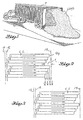
- FIG. 1 shows a load of bulk material being unloaded from a trailer T by use of a reciprocating slat conveyor within the trailer T.
- This is one use of the reciprocating slat conveyor of the present invention.
- Other uses are in stationary installations, e.g. as disclosed in U.S. Pat. No. 4,508,211, granted Apr. 2, 1985, to Raymond K. Foster, and in the aforementioned U.S. Pat. Nos. 5,340,264 and 5,469,603.
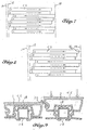
- FIGS. 2-8 illustrate the desired pattern of conveyor slat movement in a four slat conveyor. These diagrams illustrate four slat sets, designated “1,” “2,” “3” and “4,” and two "groups.”
- the conveyor must include at least one "group” but the number of groups is a variable.
- Each "group” includes one slat from each "set.” In other words, each group includes one set “1" slat, one set “2" slat, one set "3” slat, and one set "4" slat, in that order.
- a typical conveyor will include five groups (twenty slats) or six groups (twenty-four slats). The length and width of the slats are variables.
- FIG. 2 shows the desired stagger pattern of the slats.
- the slats of slat set "4" are shown in a fully retracted position, back against retract line 10.
- the distances between the forward end of a slat set "4" slat and an advanced line 14 is equal to the stroke lengths.
- This stroke length S is shown to be divided into four parts S/4.
- a third line 12 is shown spaced forwardly from retract line 10 by the amount S/4.
- FIG. 2 shows all of the slats moving together towards the advanced position 14. In FIG. 2, the set "4" slats are just starting to move.
- FIG. 3 shows the slats moved forwardly from their position in FIG. 2 by a distance S/8.
- FIG. 4 shows the positions of the slats when the set "1" slats have reached the advanced position 14 and have just started to return. At this time, the set "4" slats are the farthest to the rear and their rear ends are at line 12.
- FIG. 5 shows the slats moved forward from their FIG. 4 positions an amount equal to S/8. At this time, all of the slats are moving together towards the advanced position 14.
- FIG. 6 shows the set "2" slats at the advanced position and just starting to return, while the remaining slats are advancing.
- FIG. 7 shows the set "3" slats at the advanced position 14 and just starting to return while the other slats are advancing.
- FIG. 8 shows the set "4" slats at the advanced position 14 and just starting to return while the other slats are advancing.
- FIGS. 2-8 show the forward end of the set "1" slats spaced about S/4 from advanced line 14 at the start of retraction of the set "4" slats.
- FIG. 8 shows the forward end of the set "1" slats spaced about S/4 from advanced line 14 at the start of retraction of the set "4" slats.
- the slats are mounted for reciprocation by longitudinal support and guide beams 16 and by plastic bearings 18 that are spaced apart along the beams 16. It is customary to provide a seal member 20 that is carried by one of the slats which makes sealing contact with the adjacent side surface of the adjoining slat.
- FIG. 9 shows seal member 20 carried by slat 2 and in sliding sealing contact with slat 1.
- FIG. 9 also shows a bearing 18 positioned on a guide beam 16 and a slat 1 positioned on the bearing 18. It also shows a second bearing 18 positioned on a guide beam 16 and a slat 2 in the process of being snap-fitted down onto the bearing 18.
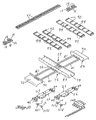
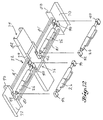
- FIGS. 10-15 show a preferred drive assembly 22 that is basically characterized by a drive assembly frame 24 and a plurality of piston-cylinder drive units 26, one for each slat set.
- the drive units 26 each comprises a pair of opposite end portions that are both mounted to the frame 24 and a movable central portion which reciprocates back and forth along the stationary portions.
- the drive module frame 24 comprises a pair of end frame members 70, 72 and a center frame member 74.
- the end members 70, 72 may be of a length to fit between a pair of laterally spaced apart main frame beams MFB (FIGS. 13 and 15).
- the center member 74 may include a lower portion 76 that includes lateral members 78, 80 that are substantially equal in length to the end members 70, 72. These lateral members 78, 80 also fit laterally between the main frame beams MFB.
- Member 74 includes an upper portion 82 that may extend substantially the full width of the conveyor frame. Upper portion 82 is in the form of a lipped channel 82. Longitudinal frame members 81 extend between the end frame members 70, 72 and the center frame member 74.
- the main frame beams MFB are shown in broken lines in FIG. 13.
- cross-sill members 84 are shown in broken lines.
- the end frame members 70, 72 include portions 88, 90 which project upwardly above the main frame beams MFB a distance substantially equal to the height of the cross-sill members 84.
- the cross-sill members 84 set down on top of and are connected to the main frame beams MFB. They also set down on and are connected to the tops of side frame members 85. At their inner ends, the cross-sill members 84 may be butt welded to the end member portions 88, 90.
- FIGS. 11 and 13 fragments of a support and guide beam 16 are shown in broken line.
- four of the bearings 18 are shown positioned on the guide beam sections 16.
- Conveyor slat CS is connected to a connector 92 that is connected to a transverse drive beam 94, also sometimes referred to as a cross drive 94.
- a separate cross drive 94 is connected to each drive unit 26. This is usually done by use of clamps, as disclosed in U.S. Pat. No. 4,793,469, granted Dec. 27, 1988, to Raymond K. Foster.
- Each cross drive 94 is connected to one set of the conveyor slats CS by use of the connectors 92. This is well disclosed in the aforementioned U.S. Pat. No. 4,748,894, for example.
- the fixed portions of the ball blocks 40, 42 are integrated into the end frame members 70, 72 in the manner disclosed by the aforementioned U.S. Pat. No. 5,390,781, for example.
- the fixed portions of the inner ball blocks 40, 42 are integrated into the center frame member 74 in substantially the same way.
- Center frame member 74 is preferably generally in the shape of an upwardly opening channel, as shown in FIG. 11. It is provided with internal strengthening members reinforcement plates 75. These plates 75 are vertically disposed and they extend transversely of the frame member 74, and longitudinally of the conveyor. Their ends are connected to sidewall portions of the lip channel 82, generally at the ends of the strengthening plates 75.
- windows in the conveyor main frame W1, W2 are formed on opposite sides of the transverse frame member 74. Owing to the construction of the drive assembly frame, the windows W1, W2 are relatively short. Two transverse drive beams 94 reciprocate back and forth in each window W1, W2. The end members 70, 72, the cross-sills 84 and the guide beams 16 provide reinforcement at the outer ends of the windows W1, W2. The transverse beam 74 and its guide beam segments 16 provide reinforcement at the inner ends of the windows W1, W2. Within the windows W1, W2, the loads imposed on the conveyor slats are picked up by the drive units 26 and transmitted to the frame members 70, 72, 74, and from such frame members to the main frame beams MFB.
- the drive units 26 are in the nature of structural beams capable of carrying bending moments, more specifically, the downward forces imposed on the conveyor slats CS are transmitted by the conveyor slats CS to the transverse drive beams 94, and from the drive beams 94 to the movable center portions of the drive units 26. They are then transmitted by the movable center portions of the drive units 26 to the end portions of the drive units 26 and from such end portions to the frame members 70, 72, 74.
- FIG. 13 shows a particular pattern of the transverse drive beams 94 connected to the cylinder barrels 48 of the drive units 26. However, it is to be understood that this pattern can change. Any one of the beams 94 can be clamped to any one of the drive units 26.
- the pattern of the beams 94 on the drive units 26 results in the far right beam 94 and the top drive unit 26 on the right being connected to the set "1" slats.
- the beam 94 that is second from the left and the upper drive unit 26 on the left are connected to the set "2" slats.
- the beam 94 second from the right and the lower drive unit 26 on the right are connected to the set "3" slats.
- the beam 94 on the left and the lower drive unit 26 on the left are connected to the set "4" slats.
Landscapes
- Engineering & Computer Science (AREA)
- Mechanical Engineering (AREA)
- Chain Conveyers (AREA)
- Reciprocating Conveyors (AREA)
Claims (8)
- Antriebsmodul (22) für einen sich hin und her bewegenden Lattenförderer, der aufweist:wobei jeder Querantriebsbalken (94) mit dem bewegbaren Abschnitt einer separaten zugehörigen Antriebseinheit der Antriebseinheiten (26) verbunden ist.ein Paar in Längsrichtung beabstandeter Endrahmenbauteile (70, 72), von denen sich jedes in Querrichtung des Förderers erstreckt;ein Zentralrahmenbauteil (74), das in Längsrichtung zwischen den beiden Endrahmenbauteilen (70, 72) positioniert ist und sich in Querrichtung des Förderers erstreckt;ein erstes Paar Kolben Zylinder-Antriebseinheiten (26), die sich in Längsrichtung des Förderers zwischen einem ersten der Endrahmenbauteile (70) und dem Zentralrahmenbauteil (74) erstrecken, wobei die Antriebseinheiten (26) jeweils einen fixierten Endabschnitt, der mit dem Zentralrahmenbauteil (74) verbunden ist, und einen bewegbaren Abschnitt zwischen dem ersten Endrahmenbauteil (70) und dem Zentralrahmenbauteil (74) aufweisen;ein zweites Paar Kolben-Zylinder-Antriebseinheiten (26), die sich in Längsrichtung des Förderers zwischen dem Zentralrahmenbauteil (74) und dem zweiten Endrahmenbauteil (72) erstrecken, wobei die Antriebseinheiten (26) jeweils einen fixierten Endabschnitt, der mit dem zweiten Endrahmenbauteil (72) verbunden ist, und einen bewegbaren Abschnitt zwischen dem zweiten Endrahmenbauteil (72) und dem Zentralrahmenbauteil (74) aufweisen;vier Querantriebsbalken (94), einen für jede Antriebseinheit, wobei zwei der Querantriebsbalken zwischen dem ersten Endrahmenbauteil (70) und dem Zentralrahmenbauteil (74) positioniert sind und wobei die verbleibenden zwei der Querantriebsbalken zwischen dem Zentralrahmenbauteil (74) und dem zweiten Endrahmenbauteil (72) positioniert sind; und
- Antriebsmodul (22) gemäß Anspruch 1, bei dem jede Antriebseinheit (26) zwei fixierte gegenüberliegende Endabschnitte und einen bewegbaren zentralen Abschnitt aufweist, wobei einer der fixierten gegenüberliegenden Endabschnitte mit einem Endrahmenbauteil (70) verbunden ist und der andere mit dem Zentralrahmenbauteil (74) verbunden ist.
- Antriebsmodul gemäß Anspruch 1, bei dem das Zentralrahmenbauteil (74) einen oberen Abschnitt (82) und eine Mehrzahl an Auflager-Träger, die mit dem oberen Abschnitt verbunden sind, aufweist, wobei die Auflager-Träger Balkenbauteile sind, die sich in Längsrichtung des Förderers erstrecken, wobei im Einsatz mit jedem Auflager-Träger mindestens ein auflagernder Teil verbunden ist und jeder Auflager-Träger und auflagernder Teil einen Abschnitt einer sich hin und her bewegenden Förderlatte (CS) aufnehmen und tragen.
- Antriebsmodul (22) gemäß Anspruch 3, bei dem das Zentralrahmenbauteil (74) die Form eines sich nach oben öffnenden Kanals (82) aufweist.
- Antriebsmodul (22) gemäß Anspruch 4, das innerhalb des Kanals (82) Verstärkungsbauteile (75), die sich in Querrichtung des Kanals (82) und in Längsrichtung des Förderers erstrecken, aufweist, wobei die Verstärkungsbauteile dort angeordnet sind, wo die Antriebseinheiten (26) mit dem Zentralrahmenbauteil verbunden sind.
- Antriebsmodul (22) gemäß Anspruch 1, bei dem die Endrahmenbauteile (70, 72) so lang sind, daß sie im wesentlichen zwischen ein Paar sich in Längsrichtung erstreckender, lateral beabstandeter Zentralrahmenbalken (MFB) passen, und wobei das Zentralrahmenbauteil (74) angepasst ist, daß es auf die Zentralrahmenbalken (MFB) aufsitzt und sich lateral von diesen nach außen, im wesentlichen zu den Seitenrändern des Förderers, erstreckt.
- Antriebsmodul (22) gemäß Anspruch 6, bei dem die Endrahmenbauteile (70, 92) obere Abschnitte (88, 90), die im Einsatz über die Zentralrahmenbalken (MFB) hochstehen, aufweisen, wobei jeder obere Abschnitt eine obere Fläche aufweist, und wobei das Zentralrahmenbauteil (74) eine obere Fläche im wesentlichen auf dem gleichen Niveau wie die oberen Flächen der Endrahmenbauteile (70, 72) aufweist, und wobei sich in Längsrichtung erstreckende Träger- und Führungsbalken (16) für Förderlatten (CS) mit den oberen Flächen der Endrahmenbauteile (90, 72) und den oberen Flächen des Zentralrahmenbauteils (94) verbunden sind.
- Antriebsmodul (22) gemäß Anspruch 7, bei dem Fenster (W1, W2) zwischen Enden der Träger- und Führungsbalken (16), die mit jedem Endrahmenbauteil (70, 72) verbunden sind, und Enden der Träger- und Führungsbalken, die mit dem Zentralrahmenbauteil (74) verbunden sind, ausgebildet sind, wobei jedes dieser Fenster (W1, W2) von oben Zugang zu zweien der Antriebsbalken (94) bietet.
Applications Claiming Priority (3)
| Application Number | Priority Date | Filing Date | Title |
|---|---|---|---|
| US1523596P | 1996-04-10 | 1996-04-10 | |
| US15235P | 1996-04-10 | ||
| EP97921129A EP0920396B1 (de) | 1996-04-10 | 1997-04-09 | Kontinuierlich fortlaufender hin- und hergehender lattenförderer |
Related Parent Applications (1)
| Application Number | Title | Priority Date | Filing Date |
|---|---|---|---|
| EP97921129A Division EP0920396B1 (de) | 1996-04-10 | 1997-04-09 | Kontinuierlich fortlaufender hin- und hergehender lattenförderer |
Publications (2)
| Publication Number | Publication Date |
|---|---|
| EP1338534A1 EP1338534A1 (de) | 2003-08-27 |
| EP1338534B1 true EP1338534B1 (de) | 2005-02-09 |
Family
ID=27665051
Family Applications (1)
| Application Number | Title | Priority Date | Filing Date |
|---|---|---|---|
| EP03075815A Expired - Lifetime EP1338534B1 (de) | 1996-04-10 | 1997-04-09 | Antriebsmodul für einen hin- und hergehenden Lattenförderer |
Country Status (1)
| Country | Link |
|---|---|
| EP (1) | EP1338534B1 (de) |
Families Citing this family (1)
| Publication number | Priority date | Publication date | Assignee | Title |
|---|---|---|---|---|
| WO2014005589A1 (en) * | 2012-07-03 | 2014-01-09 | One2Feed Aps | Feed hopper |
Family Cites Families (16)
| Publication number | Priority date | Publication date | Assignee | Title |
|---|---|---|---|---|
| NL6706657A (de) | 1967-05-12 | 1968-11-13 | ||
| US3534875A (en) | 1968-11-18 | 1970-10-20 | Olof A Hallstrom Jr | Reciprocating conveyor |
| US4144963A (en) | 1974-08-12 | 1979-03-20 | Hallstrom Olof A | Reciprocating conveyor |
| US4858748A (en) | 1982-02-08 | 1989-08-22 | Foster Raymond K | Bearing system for reciprocating floor conveyor |
| US4508211A (en) | 1982-02-08 | 1985-04-02 | Foster R Keith | Reciprocating floor conveyor apparatus and method |
| US4896761A (en) | 1982-02-08 | 1990-01-30 | Foster Raymond K | Reciprocating conveyor floor members and seals |
| US4793469A (en) | 1983-03-22 | 1988-12-27 | Foster Raymond K | Reduced size drive/frame assembly for a reciprocating floor conveyor |
| US4580678A (en) | 1984-12-11 | 1986-04-08 | Foster Raymond K | Reciprocating floor conveyor system |
| US4748894A (en) | 1986-09-08 | 1988-06-07 | Foster Raymond K | Drive/frame assembly for a reciprocating floor |
| US4793468A (en) | 1986-10-31 | 1988-12-27 | Western Waste Industries Et Al. | Multiphase sliding floor for continuous material movement |
| FI83181C (fi) | 1989-07-03 | 1991-06-10 | Rauma Repola Oy | Foerfarande och transportoer foer transport av fast material i stycken eller partiklar. |
| US5340264A (en) | 1992-04-27 | 1994-08-23 | Quaeck Manfred W | Reciprocating floor conveyor |
| US5383548A (en) * | 1992-04-27 | 1995-01-24 | Quaeck; Manfred W. | Reciprocating floor conveyor |
| US5390781A (en) | 1993-04-28 | 1995-02-21 | Foster; Raymond K. | Mounting assembly and method for reciprocating slat conveyor |
| US5469603A (en) | 1993-11-26 | 1995-11-28 | Western Steel, Inc. | Fiber reducer reciprocating conveyor having an improved bearing assembly |
| US5427229A (en) * | 1994-09-20 | 1995-06-27 | Foster; Raymond K. | Control system for reciprocating floor conveyor |
-
1997
- 1997-04-09 EP EP03075815A patent/EP1338534B1/de not_active Expired - Lifetime
Also Published As
| Publication number | Publication date |
|---|---|
| EP1338534A1 (de) | 2003-08-27 |
Similar Documents
| Publication | Publication Date | Title |
|---|---|---|
| USRE35022E (en) | Reduced size drive/frame assembly for a reciprocating floor conveyor | |
| US7461738B1 (en) | Reciprocating slat conveyors | |
| DE69732502T2 (de) | Antriebsmodul für einen hin- und hergehenden Lattenförderer | |
| DE3922248C2 (de) | Förderer mit hin- und herbewegbaren Latten | |
| KR101003664B1 (ko) | 워킹-빔 컨베이어 | |
| EP2650239B1 (de) | Lattenförderer mit Förderlatten und Hebe-/haltelatten | |
| EP2186756B1 (de) | Horizontalförderer zum Transport von Stückgütern | |
| DE2137827A1 (de) | Entladevorrichtung | |
| EP1749764B1 (de) | Hin- und hergehender Lattenförderer mit festen und bewegbaren Latten | |
| US6006896A (en) | Reciprocating slat conveyor with front end drive assembly | |
| WO2007082095A2 (en) | Reciprocating slat conveyor with bearing planks on fixed slats between moving slats | |
| EP1338534A1 (de) | Antriebsmodul für einen hin- und hergehenden Lattenförderer | |
| EP2149512A2 (de) | Förderlatten- / -hilfsstrahlanordnung für einen hin- und hergehenden Lattenförderer | |
| US7815037B2 (en) | Lifting/holding slats for a slat conveyor | |
| US20060249353A1 (en) | Reciprocating slat conveyor with V-slats | |
| EP0652172B1 (de) | Kastenbeschicker | |
| US7131526B2 (en) | Slat conveyor with V-slats and slat support beams | |
| DE3928437C2 (de) | ||
| KR102052206B1 (ko) | 사료급이기 | |
| US20110147167A1 (en) | Under-Mount Slat Conveyor | |
| KR940006118Y1 (ko) | 화물이동플로어시스템이 구성된 밴박스 | |
| CA2637671A1 (en) | Slat conveyor with v-slats and slat support beams | |
| GB1255318A (en) | Reciprocating conveyor | |
| SU1384194A3 (ru) | Цепной скребковый погрузочный конвейер | |
| SU1090637A1 (ru) | Штанговый конвейер |
Legal Events
| Date | Code | Title | Description |
|---|---|---|---|
| PUAI | Public reference made under article 153(3) epc to a published international application that has entered the european phase |
Free format text: ORIGINAL CODE: 0009012 |
|
| AC | Divisional application: reference to earlier application |
Ref document number: 0920396 Country of ref document: EP Kind code of ref document: P |
|
| AK | Designated contracting states |
Designated state(s): BE DE ES FR GB IT NL |
|
| 17P | Request for examination filed |
Effective date: 20040219 |
|
| GRAP | Despatch of communication of intention to grant a patent |
Free format text: ORIGINAL CODE: EPIDOSNIGR1 |
|
| AKX | Designation fees paid |
Designated state(s): BE DE ES FR GB IT NL |
|
| GRAS | Grant fee paid |
Free format text: ORIGINAL CODE: EPIDOSNIGR3 |
|
| GRAA | (expected) grant |
Free format text: ORIGINAL CODE: 0009210 |
|
| AC | Divisional application: reference to earlier application |
Ref document number: 0920396 Country of ref document: EP Kind code of ref document: P |
|
| AK | Designated contracting states |
Kind code of ref document: B1 Designated state(s): BE DE ES FR GB IT NL |
|
| REG | Reference to a national code |
Ref country code: GB Ref legal event code: FG4D |
|
| REF | Corresponds to: |
Ref document number: 69732502 Country of ref document: DE Date of ref document: 20050317 Kind code of ref document: P |
|
| REG | Reference to a national code |
Ref country code: ES Ref legal event code: FG2A Ref document number: 2233904 Country of ref document: ES Kind code of ref document: T3 |
|
| PLBE | No opposition filed within time limit |
Free format text: ORIGINAL CODE: 0009261 |
|
| STAA | Information on the status of an ep patent application or granted ep patent |
Free format text: STATUS: NO OPPOSITION FILED WITHIN TIME LIMIT |
|
| ET | Fr: translation filed | ||
| 26N | No opposition filed |
Effective date: 20051110 |
|
| PGFP | Annual fee paid to national office [announced via postgrant information from national office to epo] |
Ref country code: BE Payment date: 20070425 Year of fee payment: 11 |
|
| PGFP | Annual fee paid to national office [announced via postgrant information from national office to epo] |
Ref country code: DE Payment date: 20080430 Year of fee payment: 12 Ref country code: ES Payment date: 20080430 Year of fee payment: 12 |
|
| PGFP | Annual fee paid to national office [announced via postgrant information from national office to epo] |
Ref country code: IT Payment date: 20080429 Year of fee payment: 12 |
|
| BERE | Be: lapsed |
Owner name: *FOSTER RAYMOND KEITH Effective date: 20080430 |
|
| PGFP | Annual fee paid to national office [announced via postgrant information from national office to epo] |
Ref country code: NL Payment date: 20080430 Year of fee payment: 12 |
|
| PGFP | Annual fee paid to national office [announced via postgrant information from national office to epo] |
Ref country code: GB Payment date: 20080429 Year of fee payment: 12 |
|
| PG25 | Lapsed in a contracting state [announced via postgrant information from national office to epo] |
Ref country code: BE Free format text: LAPSE BECAUSE OF NON-PAYMENT OF DUE FEES Effective date: 20080430 |
|
| GBPC | Gb: european patent ceased through non-payment of renewal fee |
Effective date: 20090409 |
|
| NLV4 | Nl: lapsed or anulled due to non-payment of the annual fee |
Effective date: 20091101 |
|
| REG | Reference to a national code |
Ref country code: FR Ref legal event code: ST Effective date: 20091231 |
|
| PG25 | Lapsed in a contracting state [announced via postgrant information from national office to epo] |
Ref country code: DE Free format text: LAPSE BECAUSE OF NON-PAYMENT OF DUE FEES Effective date: 20091103 |
|
| PG25 | Lapsed in a contracting state [announced via postgrant information from national office to epo] |
Ref country code: NL Free format text: LAPSE BECAUSE OF NON-PAYMENT OF DUE FEES Effective date: 20091101 |
|
| PG25 | Lapsed in a contracting state [announced via postgrant information from national office to epo] |
Ref country code: GB Free format text: LAPSE BECAUSE OF NON-PAYMENT OF DUE FEES Effective date: 20090409 Ref country code: FR Free format text: LAPSE BECAUSE OF NON-PAYMENT OF DUE FEES Effective date: 20091222 |
|
| PGFP | Annual fee paid to national office [announced via postgrant information from national office to epo] |
Ref country code: FR Payment date: 20080430 Year of fee payment: 12 |
|
| REG | Reference to a national code |
Ref country code: ES Ref legal event code: FD2A Effective date: 20090411 |
|
| PG25 | Lapsed in a contracting state [announced via postgrant information from national office to epo] |
Ref country code: ES Free format text: LAPSE BECAUSE OF NON-PAYMENT OF DUE FEES Effective date: 20090411 |
|
| PG25 | Lapsed in a contracting state [announced via postgrant information from national office to epo] |
Ref country code: IT Free format text: LAPSE BECAUSE OF NON-PAYMENT OF DUE FEES Effective date: 20090409 |