EP1338822A2 - Procédé de fabrication d'un amortisseur dynamique - Google Patents
Procédé de fabrication d'un amortisseur dynamique Download PDFInfo
- Publication number
- EP1338822A2 EP1338822A2 EP02020739A EP02020739A EP1338822A2 EP 1338822 A2 EP1338822 A2 EP 1338822A2 EP 02020739 A EP02020739 A EP 02020739A EP 02020739 A EP02020739 A EP 02020739A EP 1338822 A2 EP1338822 A2 EP 1338822A2
- Authority
- EP
- European Patent Office
- Prior art keywords
- elastic body
- outer pipe
- weight
- dynamic damper
- convex portions
- Prior art date
- Legal status (The legal status is an assumption and is not a legal conclusion. Google has not performed a legal analysis and makes no representation as to the accuracy of the status listed.)
- Granted
Links
Images


Classifications
-
- F—MECHANICAL ENGINEERING; LIGHTING; HEATING; WEAPONS; BLASTING
- F16—ENGINEERING ELEMENTS AND UNITS; GENERAL MEASURES FOR PRODUCING AND MAINTAINING EFFECTIVE FUNCTIONING OF MACHINES OR INSTALLATIONS; THERMAL INSULATION IN GENERAL
- F16F—SPRINGS; SHOCK-ABSORBERS; MEANS FOR DAMPING VIBRATION
- F16F15/00—Suppression of vibrations in systems; Means or arrangements for avoiding or reducing out-of-balance forces, e.g. due to motion
- F16F15/10—Suppression of vibrations in rotating systems by making use of members moving with the system
- F16F15/14—Suppression of vibrations in rotating systems by making use of members moving with the system using masses freely rotating with the system, i.e. uninvolved in transmitting driveline torque, e.g. rotative dynamic dampers
- F16F15/1407—Suppression of vibrations in rotating systems by making use of members moving with the system using masses freely rotating with the system, i.e. uninvolved in transmitting driveline torque, e.g. rotative dynamic dampers the rotation being limited with respect to the driving means
- F16F15/1414—Masses driven by elastic elements
- F16F15/1421—Metallic springs, e.g. coil or spiral springs
- F16F15/1428—Metallic springs, e.g. coil or spiral springs with a single mass
-
- F—MECHANICAL ENGINEERING; LIGHTING; HEATING; WEAPONS; BLASTING
- F16—ENGINEERING ELEMENTS AND UNITS; GENERAL MEASURES FOR PRODUCING AND MAINTAINING EFFECTIVE FUNCTIONING OF MACHINES OR INSTALLATIONS; THERMAL INSULATION IN GENERAL
- F16F—SPRINGS; SHOCK-ABSORBERS; MEANS FOR DAMPING VIBRATION
- F16F15/00—Suppression of vibrations in systems; Means or arrangements for avoiding or reducing out-of-balance forces, e.g. due to motion
- F16F15/10—Suppression of vibrations in rotating systems by making use of members moving with the system
- F16F15/12—Suppression of vibrations in rotating systems by making use of members moving with the system using elastic members or friction-damping members, e.g. between a rotating shaft and a gyratory mass mounted thereon
- F16F15/121—Suppression of vibrations in rotating systems by making use of members moving with the system using elastic members or friction-damping members, e.g. between a rotating shaft and a gyratory mass mounted thereon using springs as elastic members, e.g. metallic springs
- F16F15/1214—Folded springs, i.e. made of band-like material folded in an enclosing space
-
- Y—GENERAL TAGGING OF NEW TECHNOLOGICAL DEVELOPMENTS; GENERAL TAGGING OF CROSS-SECTIONAL TECHNOLOGIES SPANNING OVER SEVERAL SECTIONS OF THE IPC; TECHNICAL SUBJECTS COVERED BY FORMER USPC CROSS-REFERENCE ART COLLECTIONS [XRACs] AND DIGESTS
- Y10—TECHNICAL SUBJECTS COVERED BY FORMER USPC
- Y10T—TECHNICAL SUBJECTS COVERED BY FORMER US CLASSIFICATION
- Y10T29/00—Metal working
- Y10T29/49—Method of mechanical manufacture
- Y10T29/49826—Assembling or joining
- Y10T29/49863—Assembling or joining with prestressing of part
- Y10T29/4987—Elastic joining of parts
- Y10T29/49872—Confining elastic part in socket
-
- Y—GENERAL TAGGING OF NEW TECHNOLOGICAL DEVELOPMENTS; GENERAL TAGGING OF CROSS-SECTIONAL TECHNOLOGIES SPANNING OVER SEVERAL SECTIONS OF THE IPC; TECHNICAL SUBJECTS COVERED BY FORMER USPC CROSS-REFERENCE ART COLLECTIONS [XRACs] AND DIGESTS
- Y10—TECHNICAL SUBJECTS COVERED BY FORMER USPC
- Y10T—TECHNICAL SUBJECTS COVERED BY FORMER US CLASSIFICATION
- Y10T29/00—Metal working
- Y10T29/49—Method of mechanical manufacture
- Y10T29/49826—Assembling or joining
- Y10T29/49908—Joining by deforming
- Y10T29/49909—Securing cup or tube between axially extending concentric annuli
- Y10T29/49913—Securing cup or tube between axially extending concentric annuli by constricting outer annulus
-
- Y—GENERAL TAGGING OF NEW TECHNOLOGICAL DEVELOPMENTS; GENERAL TAGGING OF CROSS-SECTIONAL TECHNOLOGIES SPANNING OVER SEVERAL SECTIONS OF THE IPC; TECHNICAL SUBJECTS COVERED BY FORMER USPC CROSS-REFERENCE ART COLLECTIONS [XRACs] AND DIGESTS
- Y10—TECHNICAL SUBJECTS COVERED BY FORMER USPC
- Y10T—TECHNICAL SUBJECTS COVERED BY FORMER US CLASSIFICATION
- Y10T29/00—Metal working
- Y10T29/49—Method of mechanical manufacture
- Y10T29/49826—Assembling or joining
- Y10T29/49908—Joining by deforming
- Y10T29/49925—Inward deformation of aperture or hollow body wall
-
- Y—GENERAL TAGGING OF NEW TECHNOLOGICAL DEVELOPMENTS; GENERAL TAGGING OF CROSS-SECTIONAL TECHNOLOGIES SPANNING OVER SEVERAL SECTIONS OF THE IPC; TECHNICAL SUBJECTS COVERED BY FORMER USPC CROSS-REFERENCE ART COLLECTIONS [XRACs] AND DIGESTS
- Y10—TECHNICAL SUBJECTS COVERED BY FORMER USPC
- Y10T—TECHNICAL SUBJECTS COVERED BY FORMER US CLASSIFICATION
- Y10T29/00—Metal working
- Y10T29/49—Method of mechanical manufacture
- Y10T29/49826—Assembling or joining
- Y10T29/49945—Assembling or joining by driven force fit
Definitions
- an elastic body is disposed in an annular space between an outer pipe and a weight, and a rod-like elastic interposed portion is provided so as to extend in the radius direction at each of a plurality of positions (five positions) in the circumferential direction of the annular space.
- An object of the present invention is to secure a stable spring constant in an elastic body of a dynamic damper so as to acquire a stable damping characteristic.
- a manufacturing method of a dynamic damper comprising an outer pipe, a weight disposed inside the outer pipe and an elastic body interposed between the outer pipe and the weight.
- the steps include forming an annular elastic body, fitting a weight in an inner periphery of the annular elastic body and fitting an outer pipe on an outer periphery thereof, and bonding the weight and the outer pipe to the inner periphery and the outer periphery of the annular elastic body respectively.
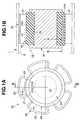
- FIGS. 1A and 1B show a dynamic damper of the first embodiment, where FIG. 1A is a front view thereof and FIG. 1B is a sectional view taken along the line B-B;
- the dynamic damper 10 comprises an outer pipe 20, a weight 30 and an elastic body 40.
- the elastic body 40 is an annular body fitted to an annular groove 31 in the weight 30 over the entire periphery between the outer pipe 20 and the weight 30.
- the outer periphery of the elastic body 40 has a larger diameter than an outer diameter of the weight 30 and is formed with arc faces continuous along the entire periphery.
- the elastic body 40 is formed of synthetic rubber or the like and is bonded to the outer pipe 20 and the weight 30 by vulcanization.
- the elastic body 40 on the weight 30 is nipped and held by a front end pressure-contact face 21A of each convex portion 21 of the outer pipe 20 from radial directions.
- An outer peripheral portion 41 of the elastic body 40 is nipped and held in the circumferential direction between the front end pressure-contact faces 21A of the convex portions 21 adjacent in the circumferential direction of the outer pipe 20.
- the front end pressure-contact face 21A of each convex portion 21 engages the outer peripheral portion 41 of the elastic body 40 in a specified depth so that the outer peripheral portion 41A is nipped between the front end pressure-contact faces 21A of the adjacent convex portions 21.
- This embodiment exhibits the following characteristics.
- the manufacturing procedure for the dynamic damper 100 is as follows (FIGS. 5A to 5E).
- the outer peripheral portion 41A of the elastic body 40 can be nipped and held firmly between the convex portions 21 of the outer pipe 20 adjacent to each other. Repeated load due to compression in the radial direction from the weight 30 and shearing stress in the rotation direction based on rotary vibration of the propeller shaft 1 is distributed widely to respective portions of the elastic body 40. Therefore, concentration of stress upon the elastic body 40 can be suppressed so as to prevent damage by cracks, thereby improving the durability of the dynamic damper 10.
Landscapes
- Engineering & Computer Science (AREA)
- General Engineering & Computer Science (AREA)
- Physics & Mathematics (AREA)
- Acoustics & Sound (AREA)
- Aviation & Aerospace Engineering (AREA)
- Mechanical Engineering (AREA)
- Motor Power Transmission Devices (AREA)
- Vibration Prevention Devices (AREA)
- Pulleys (AREA)
Applications Claiming Priority (2)
| Application Number | Priority Date | Filing Date | Title |
|---|---|---|---|
| JP2002047018A JP3897610B2 (ja) | 2002-02-22 | 2002-02-22 | ダイナミックダンパの製法 |
| JP2002047018 | 2002-02-22 |
Publications (3)
| Publication Number | Publication Date |
|---|---|
| EP1338822A2 true EP1338822A2 (fr) | 2003-08-27 |
| EP1338822A3 EP1338822A3 (fr) | 2004-07-28 |
| EP1338822B1 EP1338822B1 (fr) | 2007-08-01 |
Family
ID=27655370
Family Applications (1)
| Application Number | Title | Priority Date | Filing Date |
|---|---|---|---|
| EP02020739A Expired - Lifetime EP1338822B1 (fr) | 2002-02-22 | 2002-09-16 | Procédé de fabrication d'un amortisseur dynamique |
Country Status (4)
| Country | Link |
|---|---|
| US (1) | US7010843B2 (fr) |
| EP (1) | EP1338822B1 (fr) |
| JP (1) | JP3897610B2 (fr) |
| DE (1) | DE60221495T2 (fr) |
Families Citing this family (7)
| Publication number | Priority date | Publication date | Assignee | Title |
|---|---|---|---|---|
| DE202006012132U1 (de) * | 2006-08-08 | 2006-10-05 | Roland Meinl Musikinstrumente Gmbh & Co. Kg | Conga-Ständer |
| US8308588B2 (en) * | 2009-04-28 | 2012-11-13 | Schaeffler Technologies AG & Co. KG | Timing chain pivoting guide having a rubber spring element |
| US8167730B2 (en) * | 2009-09-21 | 2012-05-01 | Gkn Driveline North America, Inc. | Tuned absorber |
| DE102010022866A1 (de) * | 2010-06-07 | 2011-12-08 | Benteler Automobiltechnik Gmbh | Verfahren zum Herstellen einer Stabilisatoranordnung sowie eine Stabilisatoranordnung |
| US8720920B2 (en) * | 2012-08-29 | 2014-05-13 | Williams-Bayer Industries Inc. | Sleeve, sub-assembly, vehicular suspension assembly and methods for forming/assembling the same |
| DE102018106365B4 (de) * | 2017-03-24 | 2022-05-19 | Benteler Automobiltechnik Gmbh | Lageranordnung |
| US10907698B2 (en) | 2018-05-03 | 2021-02-02 | Nissan North America, Inc. | Dynamic damper |
Citations (1)
| Publication number | Priority date | Publication date | Assignee | Title |
|---|---|---|---|---|
| JPH0729324U (ja) | 1993-11-09 | 1995-06-02 | 株式会社ユニシアジェックス | プロペラシャフトのセンターベアリング |
Family Cites Families (13)
| Publication number | Priority date | Publication date | Assignee | Title |
|---|---|---|---|---|
| DE835314C (de) | 1948-10-02 | 1952-03-31 | Licentia Gmbh | Selbsttaetige Anlassschaltung fuer an Anzapftransformatoren angeschlossene Motoren, insbesondere fuer Hilfsmotoren auf elektrischen Fahrzeugen |
| GB835314A (en) * | 1957-07-15 | 1960-05-18 | Metalastik Ltd | Rubber-metal assemblies |
| JPS6014627A (ja) * | 1983-07-06 | 1985-01-25 | Nissan Motor Co Ltd | サスペンションメンバの筒状弾性ブッシュ |
| DE4111233C2 (de) | 1991-04-08 | 1994-06-16 | Freudenberg Carl Fa | Drehschwingungsdämpfer |
| US5413374A (en) * | 1991-08-30 | 1995-05-09 | Nai Neway, Inc. | Adjustable bushing |
| US5865429A (en) * | 1994-05-18 | 1999-02-02 | Caoutchouc Manufacture Et Plastiques | Elastic support including at least two cylindrical sleeves with folds |
| DE4421532C2 (de) | 1994-06-20 | 1996-08-08 | Clouth Gummiwerke Ag | Bausatz für den Zusammenbau von Schwingungstilgern |
| JP3753191B2 (ja) * | 1995-04-24 | 2006-03-08 | 株式会社ショーワ | プロペラシャフトのダイナミックダンパー取付構造 |
| JP3698217B2 (ja) * | 1995-06-27 | 2005-09-21 | 株式会社ショーワ | プロペラシャフトのダイナミックダンパー構造 |
| JP3815696B2 (ja) * | 1995-12-15 | 2006-08-30 | 株式会社ショーワ | プロペラシャフトのダイナミックダンパー構造 |
| DE19733478B4 (de) * | 1997-08-02 | 2006-03-23 | Daimlerchrysler Ag | Schwingungsdämpfer für eine rohrförmige Gelenkwelle |
| JP3848840B2 (ja) * | 2001-01-29 | 2006-11-22 | 東海ゴム工業株式会社 | 防振装置 |
| US6845995B2 (en) * | 2002-11-08 | 2005-01-25 | Visteon Global Technologies, Inc. | Method of forming compression gripped bushing system |
-
2002
- 2002-02-22 JP JP2002047018A patent/JP3897610B2/ja not_active Expired - Fee Related
- 2002-09-13 US US10/243,161 patent/US7010843B2/en not_active Expired - Fee Related
- 2002-09-16 DE DE60221495T patent/DE60221495T2/de not_active Expired - Lifetime
- 2002-09-16 EP EP02020739A patent/EP1338822B1/fr not_active Expired - Lifetime
Patent Citations (1)
| Publication number | Priority date | Publication date | Assignee | Title |
|---|---|---|---|---|
| JPH0729324U (ja) | 1993-11-09 | 1995-06-02 | 株式会社ユニシアジェックス | プロペラシャフトのセンターベアリング |
Also Published As
| Publication number | Publication date |
|---|---|
| US20030159268A1 (en) | 2003-08-28 |
| DE60221495D1 (de) | 2007-09-13 |
| DE60221495T2 (de) | 2008-04-30 |
| EP1338822B1 (fr) | 2007-08-01 |
| EP1338822A3 (fr) | 2004-07-28 |
| US7010843B2 (en) | 2006-03-14 |
| JP2003247593A (ja) | 2003-09-05 |
| JP3897610B2 (ja) | 2007-03-28 |
Similar Documents
| Publication | Publication Date | Title |
|---|---|---|
| US7044276B2 (en) | Dynamic damper and propeller shaft | |
| US7010843B2 (en) | Manufacturing method for dynamic damper | |
| JP2002098193A (ja) | 筒型ダイナミックダンパ | |
| US20030218284A1 (en) | Dynamic damper | |
| JP2003035320A (ja) | 弾性軸継手および弾性ブッシュの製造方法 | |
| JP2004144288A (ja) | ダイナミックダンパ | |
| JP3882903B2 (ja) | ダイナミックダンパ及びプロペラシャフト | |
| JP2010031926A (ja) | ダイナミックダンパ | |
| JP3882902B2 (ja) | ダイナミックダンパ及びプロペラシャフト | |
| US20180119789A1 (en) | Friction pulley | |
| JP2000249180A (ja) | リーフスプリング用ブッシュ | |
| US11719300B2 (en) | Elastic articulation | |
| JP2002276714A (ja) | 防振装置 | |
| JP2009008118A (ja) | ラバーブッシュ | |
| US20090017923A1 (en) | Rotation Drive Force Transmission Mechanism, Constant Velocity Universal Joint and Resin Joint Boot Constructing the Mechanism, and Method of Tightening Clamp Band for Constant Velocity Universal Joint | |
| JP2003222189A (ja) | トルクロッドブッシュ | |
| JPH1026183A (ja) | ダイナミックダンパの製造方法 | |
| JP4798364B2 (ja) | トルク変動吸収ダンパ | |
| JPS5916585Y2 (ja) | ト−シヨナルダンパ | |
| EP3812608B1 (fr) | Support et procédé d'assemblage d'un support | |
| JP2003227546A (ja) | 防振装置及びその製造方法 | |
| JPS62180131A (ja) | トーショナルダンパーの製造方法 | |
| JPH02261934A (ja) | 絞りブッシュの製造方法 | |
| JPH0512779U (ja) | ブツシユ | |
| JP2007016805A (ja) | トーショナルダンパ |
Legal Events
| Date | Code | Title | Description |
|---|---|---|---|
| PUAI | Public reference made under article 153(3) epc to a published international application that has entered the european phase |
Free format text: ORIGINAL CODE: 0009012 |
|
| AK | Designated contracting states |
Designated state(s): AT BE BG CH CY CZ DE DK EE ES FI FR GB GR IE IT LI LU MC NL PT SE SK TR |
|
| AX | Request for extension of the european patent |
Extension state: AL LT LV MK RO SI |
|
| PUAL | Search report despatched |
Free format text: ORIGINAL CODE: 0009013 |
|
| AK | Designated contracting states |
Kind code of ref document: A3 Designated state(s): AT BE BG CH CY CZ DE DK EE ES FI FR GB GR IE IT LI LU MC NL PT SE SK TR |
|
| AX | Request for extension of the european patent |
Extension state: AL LT LV MK RO SI |
|
| RIC1 | Information provided on ipc code assigned before grant |
Ipc: 7F 16F 15/14 A Ipc: 7F 16F 1/36 B |
|
| 17P | Request for examination filed |
Effective date: 20040901 |
|
| AKX | Designation fees paid |
Designated state(s): DE GB |
|
| 17Q | First examination report despatched |
Effective date: 20050429 |
|
| 17Q | First examination report despatched |
Effective date: 20050429 |
|
| 17Q | First examination report despatched |
Effective date: 20050429 |
|
| GRAP | Despatch of communication of intention to grant a patent |
Free format text: ORIGINAL CODE: EPIDOSNIGR1 |
|
| GRAS | Grant fee paid |
Free format text: ORIGINAL CODE: EPIDOSNIGR3 |
|
| GRAA | (expected) grant |
Free format text: ORIGINAL CODE: 0009210 |
|
| AK | Designated contracting states |
Kind code of ref document: B1 Designated state(s): DE GB |
|
| REG | Reference to a national code |
Ref country code: GB Ref legal event code: FG4D |
|
| REF | Corresponds to: |
Ref document number: 60221495 Country of ref document: DE Date of ref document: 20070913 Kind code of ref document: P |
|
| PLBE | No opposition filed within time limit |
Free format text: ORIGINAL CODE: 0009261 |
|
| STAA | Information on the status of an ep patent application or granted ep patent |
Free format text: STATUS: NO OPPOSITION FILED WITHIN TIME LIMIT |
|
| 26N | No opposition filed |
Effective date: 20080506 |
|
| PGFP | Annual fee paid to national office [announced via postgrant information from national office to epo] |
Ref country code: GB Payment date: 20150916 Year of fee payment: 14 Ref country code: DE Payment date: 20150908 Year of fee payment: 14 |
|
| REG | Reference to a national code |
Ref country code: DE Ref legal event code: R119 Ref document number: 60221495 Country of ref document: DE |
|
| GBPC | Gb: european patent ceased through non-payment of renewal fee |
Effective date: 20160916 |
|
| PG25 | Lapsed in a contracting state [announced via postgrant information from national office to epo] |
Ref country code: GB Free format text: LAPSE BECAUSE OF NON-PAYMENT OF DUE FEES Effective date: 20160916 Ref country code: DE Free format text: LAPSE BECAUSE OF NON-PAYMENT OF DUE FEES Effective date: 20170401 |