EP1339496B1 - Probenzuführsystem mit laminarmischung zur biodetektion von mikrovolumen - Google Patents
Probenzuführsystem mit laminarmischung zur biodetektion von mikrovolumen Download PDFInfo
- Publication number
- EP1339496B1 EP1339496B1 EP01990651A EP01990651A EP1339496B1 EP 1339496 B1 EP1339496 B1 EP 1339496B1 EP 01990651 A EP01990651 A EP 01990651A EP 01990651 A EP01990651 A EP 01990651A EP 1339496 B1 EP1339496 B1 EP 1339496B1
- Authority
- EP
- European Patent Office
- Prior art keywords
- sample
- microchannel
- sample chamber
- proteins
- molecules
- Prior art date
- Legal status (The legal status is an assumption and is not a legal conclusion. Google has not performed a legal analysis and makes no representation as to the accuracy of the status listed.)
- Expired - Lifetime
Links
Images


Classifications
-
- B—PERFORMING OPERATIONS; TRANSPORTING
- B01—PHYSICAL OR CHEMICAL PROCESSES OR APPARATUS IN GENERAL
- B01L—CHEMICAL OR PHYSICAL LABORATORY APPARATUS FOR GENERAL USE
- B01L3/00—Containers or dishes for laboratory use, e.g. laboratory glassware; Droppers
- B01L3/50—Containers for the purpose of retaining a material to be analysed, e.g. test tubes
- B01L3/502—Containers for the purpose of retaining a material to be analysed, e.g. test tubes with fluid transport, e.g. in multi-compartment structures
- B01L3/5027—Containers for the purpose of retaining a material to be analysed, e.g. test tubes with fluid transport, e.g. in multi-compartment structures by integrated microfluidic structures, i.e. dimensions of channels and chambers are such that surface tension forces are important, e.g. lab-on-a-chip
- B01L3/502769—Containers for the purpose of retaining a material to be analysed, e.g. test tubes with fluid transport, e.g. in multi-compartment structures by integrated microfluidic structures, i.e. dimensions of channels and chambers are such that surface tension forces are important, e.g. lab-on-a-chip characterised by multiphase flow arrangements
- B01L3/502784—Containers for the purpose of retaining a material to be analysed, e.g. test tubes with fluid transport, e.g. in multi-compartment structures by integrated microfluidic structures, i.e. dimensions of channels and chambers are such that surface tension forces are important, e.g. lab-on-a-chip characterised by multiphase flow arrangements specially adapted for droplet or plug flow, e.g. digital microfluidics
-
- B—PERFORMING OPERATIONS; TRANSPORTING
- B01—PHYSICAL OR CHEMICAL PROCESSES OR APPARATUS IN GENERAL
- B01F—MIXING, e.g. DISSOLVING, EMULSIFYING OR DISPERSING
- B01F31/00—Mixers with shaking, oscillating, or vibrating mechanisms
- B01F31/65—Mixers with shaking, oscillating, or vibrating mechanisms the materials to be mixed being directly submitted to a pulsating movement, e.g. by means of an oscillating piston or air column
-
- B—PERFORMING OPERATIONS; TRANSPORTING
- B01—PHYSICAL OR CHEMICAL PROCESSES OR APPARATUS IN GENERAL
- B01F—MIXING, e.g. DISSOLVING, EMULSIFYING OR DISPERSING
- B01F31/00—Mixers with shaking, oscillating, or vibrating mechanisms
- B01F31/65—Mixers with shaking, oscillating, or vibrating mechanisms the materials to be mixed being directly submitted to a pulsating movement, e.g. by means of an oscillating piston or air column
- B01F31/651—Mixing by successively aspirating a part of the mixture in a conduit, e.g. a piston, and reinjecting it through the same conduit into the receptacle
-
- B—PERFORMING OPERATIONS; TRANSPORTING
- B01—PHYSICAL OR CHEMICAL PROCESSES OR APPARATUS IN GENERAL
- B01F—MIXING, e.g. DISSOLVING, EMULSIFYING OR DISPERSING
- B01F33/00—Other mixers; Mixing plants; Combinations of mixers
- B01F33/30—Micromixers
-
- B—PERFORMING OPERATIONS; TRANSPORTING
- B01—PHYSICAL OR CHEMICAL PROCESSES OR APPARATUS IN GENERAL
- B01F—MIXING, e.g. DISSOLVING, EMULSIFYING OR DISPERSING
- B01F35/00—Accessories for mixers; Auxiliary operations or auxiliary devices; Parts or details of general application
- B01F35/71—Feed mechanisms
- B01F35/717—Feed mechanisms characterised by the means for feeding the components to the mixer
- B01F35/7176—Feed mechanisms characterised by the means for feeding the components to the mixer using pumps
- B01F35/717613—Piston pumps
-
- B—PERFORMING OPERATIONS; TRANSPORTING
- B01—PHYSICAL OR CHEMICAL PROCESSES OR APPARATUS IN GENERAL
- B01L—CHEMICAL OR PHYSICAL LABORATORY APPARATUS FOR GENERAL USE
- B01L3/00—Containers or dishes for laboratory use, e.g. laboratory glassware; Droppers
- B01L3/50—Containers for the purpose of retaining a material to be analysed, e.g. test tubes
- B01L3/502—Containers for the purpose of retaining a material to be analysed, e.g. test tubes with fluid transport, e.g. in multi-compartment structures
- B01L3/5027—Containers for the purpose of retaining a material to be analysed, e.g. test tubes with fluid transport, e.g. in multi-compartment structures by integrated microfluidic structures, i.e. dimensions of channels and chambers are such that surface tension forces are important, e.g. lab-on-a-chip
- B01L3/50273—Containers for the purpose of retaining a material to be analysed, e.g. test tubes with fluid transport, e.g. in multi-compartment structures by integrated microfluidic structures, i.e. dimensions of channels and chambers are such that surface tension forces are important, e.g. lab-on-a-chip characterised by the means or forces applied to move the fluids
-
- G—PHYSICS
- G06—COMPUTING OR CALCULATING; COUNTING
- G06Q—INFORMATION AND COMMUNICATION TECHNOLOGY [ICT] SPECIALLY ADAPTED FOR ADMINISTRATIVE, COMMERCIAL, FINANCIAL, MANAGERIAL OR SUPERVISORY PURPOSES; SYSTEMS OR METHODS SPECIALLY ADAPTED FOR ADMINISTRATIVE, COMMERCIAL, FINANCIAL, MANAGERIAL OR SUPERVISORY PURPOSES, NOT OTHERWISE PROVIDED FOR
- G06Q20/00—Payment architectures, schemes or protocols
- G06Q20/08—Payment architectures
- G06Q20/10—Payment architectures specially adapted for electronic funds transfer [EFT] systems; specially adapted for home banking systems
- G06Q20/102—Bill distribution or payments
-
- B—PERFORMING OPERATIONS; TRANSPORTING
- B01—PHYSICAL OR CHEMICAL PROCESSES OR APPARATUS IN GENERAL
- B01F—MIXING, e.g. DISSOLVING, EMULSIFYING OR DISPERSING
- B01F2215/00—Auxiliary or complementary information in relation with mixing
- B01F2215/04—Technical information in relation with mixing
- B01F2215/0413—Numerical information
- B01F2215/0418—Geometrical information
- B01F2215/0431—Numerical size values, e.g. diameter of a hole or conduit, area, volume, length, width, or ratios thereof
-
- B—PERFORMING OPERATIONS; TRANSPORTING
- B01—PHYSICAL OR CHEMICAL PROCESSES OR APPARATUS IN GENERAL
- B01L—CHEMICAL OR PHYSICAL LABORATORY APPARATUS FOR GENERAL USE
- B01L2200/00—Solutions for specific problems relating to chemical or physical laboratory apparatus
- B01L2200/06—Fluid handling related problems
- B01L2200/0673—Handling of plugs of fluid surrounded by immiscible fluid
-
- B—PERFORMING OPERATIONS; TRANSPORTING
- B01—PHYSICAL OR CHEMICAL PROCESSES OR APPARATUS IN GENERAL
- B01L—CHEMICAL OR PHYSICAL LABORATORY APPARATUS FOR GENERAL USE
- B01L2300/00—Additional constructional details
- B01L2300/06—Auxiliary integrated devices, integrated components
- B01L2300/0627—Sensor or part of a sensor is integrated
- B01L2300/0636—Integrated biosensor, microarrays
-
- G—PHYSICS
- G01—MEASURING; TESTING
- G01N—INVESTIGATING OR ANALYSING MATERIALS BY DETERMINING THEIR CHEMICAL OR PHYSICAL PROPERTIES
- G01N35/00—Automatic analysis not limited to methods or materials provided for in any single one of groups G01N1/00 - G01N33/00; Handling materials therefor
- G01N2035/00178—Special arrangements of analysers
- G01N2035/00237—Handling microquantities of analyte, e.g. microvalves, capillary networks
-
- G—PHYSICS
- G01—MEASURING; TESTING
- G01N—INVESTIGATING OR ANALYSING MATERIALS BY DETERMINING THEIR CHEMICAL OR PHYSICAL PROPERTIES
- G01N35/00—Automatic analysis not limited to methods or materials provided for in any single one of groups G01N1/00 - G01N33/00; Handling materials therefor
- G01N2035/00465—Separating and mixing arrangements
- G01N2035/00514—Stationary mixing elements
Definitions
- the invention relates to an apparatus and method used for mixing and sampling small volumes of liquids useful in microanalysis.
- the invention is particularly applicable to biosensing techniques.
- the measurement is based on changes in the optical properties of a sensor surface due to binding of a mobile reaction partner (the analyte) to surface-immobilized reaction partner on the sensor surface.
- Biosensing monitors the reaction of analyte molecules in a sample with a binding surface in a sample chamber.
- the sensor also includes a detector for measuring molecular binding.
- analyte molecules in the vicinity of the sensor surface can be rapidly depleted.
- the rate of molecular diffusion through the sample can be slow, and optimal sensitivity compromised in the absence of mixing or some other form of increasing the mass transfer rate. This may be particularly true if the measured quantity is not the concentration of analyte molecules, but their binding rate, as is the case in some commercial affinity biosensors.
- Several different techniques for sample handling in optical biosensors have been implemented in different commercial instruments. The primary designs used in commercial instruments are cuvettes and continuous flow microfluidics.
- Continuous flow systems such as, for example, the Biacore SPR sensor, typically incorporate an HPLC-like injection loop having a volume of from about 25 ⁇ l to about 200 ⁇ l.
- HPLC-like injection loop having a volume of from about 25 ⁇ l to about 200 ⁇ l.
- Such systems suffer from a requirement for continuous sample consumption during the observation of the binding process, but exhibit superior results with respect to stability and surface transport. Due to the limited volume of the injection loop, these systems provide only a limited contact time of the sample with the surface, which can limit the sensitivity and is frequently too short for many quantitative studies.
- microchannels deliver the sample to a sample chamber with a constant unidirectional flow.
- the sample exits the microchannel and is disposed of through a drain.
- the sample is constantly replenished in the sample chamber to avoid the generation of a depletion zone (i.e. a zone where the concentration of analyte molecules is reduced locally) in the vicinity of the sensor surface.
- a depletion zone i.e. a zone where the concentration of analyte molecules is reduced locally
- the analyte in the depletion zone is replenished more efficiently at higher flow rates.
- a relatively large volume of sample can be required to allow for sufficient reaction time, adequate mass transfer (i.e.
- the kinetic response allows the observation of the intrinsic bimolecular reaction, unconstrained by the mass transfer to the surface) and optimal observation time.
- from about 30 ⁇ l to about 200 ⁇ l of sample are required, and small volumes may allow only very short reaction times with a concomitant loss in observation time.
- the cuvette design can be problematic with respect to baseline stability and/or mass transfer rate, i.e. molecular migration to the detector surface.
- mass transfer rate i.e. molecular migration to the detector surface.
- a stirrer is inserted in the cuvette to reduce the depletion zone over the sensor surface.
- large sample volumes 100-200 ⁇ l are required.
- U.S. Patent Nos. 5,628,961 and related 5,447,440 to Davies et al. disclose an apparatus used to detect changes in the viscosity of a fluid medium by monitoring changes in the fluid oscillation frequency or amplitude.
- the apparatus disclosed in these patents utilize a back and forth motion of liquid across a sensor to increase sample exposure.
- the apparatus may be used for immunoassay purposes similar to biosensors.
- the patents describe a method and apparatus useful only for immunoassays that measure changes in viscosity, which is quite different from measuring molecular affinity, binding properties and the like.
- U.S. Patent No. 6,043,080 to Lipshutz et al. discloses a microanalytical device which may have mixing means incorporated therein.
- the apparatus is primarily applicable to PCR devices, and the patent mentions the possibility of using a mixing element.
- the patent indicates that mixing may be accomplished by pumping the sample into and out of a chambers using a back and forth motion before being output for analysis.
- This patent also discloses other possible mixing means, such as acoustic mixing and the use of mixing elements which create turbulence in the sample. The possibility of constant analysis or the use of laminar mixing to enhance reaction at an analytical surface is not mentioned.
- U.S. Patent No. 6,065,864 to Evans et al. discloses a microelectromechanical device which mixes fluids using laminar flow principles. This patent defines mixing as "combining two fluids, increasing the uniformity of a single fluid or decreasing the spatial or temporal gradients of fluid properties". The patent describes mixing due to laminar flow within a mixing chamber and uses a set of bubble valves to establish the flow in the chamber. After mixing, fluid is unloaded from the chamber in order to be analyzed or further treated. Thus, this patent discloses a device that achieves laminar mixing in a mixing chamber prior to being sent to a sensor and does not perform detection until after mixing is complete. This is not useful where constant mixing is required during the course of analysis. Furthermore, the mixing is primarily directed to changing the bulk properties of the fluids rather than causing molecular mixing to increase contact with a sensor surface.
- U.S. Patent No. 5,885,527 to Buechler discloses a diagnostic device which may be useful for small quantities of fluid.
- the device disclosed in this patent utilizes only unidirectional flow of the analyte over a ridged analytical surface leading to a waste reservoir.
- the sample reservoir is typically larger than the reaction chamber and analytical section of the device.
- the device realizes an optimization of the capture of reagents in the ridged analytical diagnostic zone by increasing surface area.
- the patent requires unidirectional flow and that excess sample remain in the sample addition reservoir and thus a relatively large volume of sample would be required.
- an increased surface area does not alone address the problem of the generation of a depletion zone at the sensor surface and the time-course of binding remains limited.
- U.S. Patent No. 5,731,212 to Gavin et al. achieves mixing through the use of protrusions within the microfluid channels to create turbulent flow.
- U.S. Patent No. 5,646,039 to Northup and White discloses the use a Lamb-Wave Transducer as an agitator, mixer and sonochemical inducer.
- U.S. Patent No. 5,904,424 to Schwesinger and Frank.
- This device comprises a single microchannel that is bifurcated into two microchannels. Mixing is achieved by the interaction of the flow where the two microchannels come together and by a change in the three dimensional direction of flow, i.e., a horizontal flow is redirected into a vertical flow.
- biosensors In drug discovery and biomedical research, the use of biosensors centers on measuring molecular properties of the analyte molecules, rather than their concentration. Among the most important properties studied are kinetic and equilibrium binding constants for the interaction of the analyte with a surface-immobilized target site. Problems frequently encountered in the application of optical biosensors include the deviation from single-exponential binding progress, which the theory predicts for simple bimolecular interactions. This is a difficult situation, because in addition to possible complex biomolecular interaction kinetics, which can be very difficult to unravel (R.W. Glaser, G. Hausdorf (1996) J. Immunol.
- thermodynamic aspects of the interaction are measured by interpretation of the equilibrium competition isotherm, from which the thermodynamics of the solution interaction can be measured.
- a competition isotherm requires only that a reproducible calibration curve as a function of analyte concentration generated through some more or less arbitrary (but quantitative) feature of the sensor response, and a second mobile reactant that is introduced to compete with the immobilized sites for the interactions of the analyte that does not interact itself with the surface.
- a device for molecular sensing comprising:
- the present invention succeeds where previous efforts have failed by allowing microanalysis of very small sample volumes with efficient molecular mixing.
- the present invention differs from conventional systems and methods in modifications which were not previously known or suggested by providing a biosensor sample delivery system that can utilize small volume of sample with sufficient molecular mixing to provide high sensitivity. Molecular mixing by oscillating laminar flow has not been previously incorporated into a biosensor device.
- the present invention satisfies a long felt need for a highly sensitive microanalytical device that requires only very small sample volumes.
- the present invention further differs from conventional systems and methods by using constant laminar mixing to facilitate molecular mixing in biosensors and other microanalytical devices.
- An apparatus comprises at least two microchannels in fluid communication with a sample chamber containing a microanalytical device such as a biosensor.
- a sample plug with a volume on the order of about 2 ⁇ l to about 15 ⁇ l is positioned in the sample chamber and spans the surrounding microchannels. Efficient laminar mixing can be accomplished by applying an oscillatory back and forth flow pattern, which minimizes the formation of a depletion zone of analyte across the detector surface.
- At least one of the microchannels or the sample chamber is sufficiently small to achieve laminar mixing from the velocity profile of the flow and, in combination with diffusion in the direction perpendicular to the flow, can generate molecular mixing and replenishment of analyte in the depletion zone.
- the sample chamber is constantly filled with fluid.
- the present invention can give responses equivalent to, within an acceptable margin, responses obtained from traditional application of a continuous unidirectional flow with high sample volume and high flow rate.
- several such small volume sample plugs can be manipulated and fully recovered in a serial fashion using the present invention.
- Use of multiple sample plugs can allow sequential study of the surface binding signal at different sample concentrations, for example.
- biosensor experiments can be conducted at significantly lower sample volumes for the analyte and, if applied during the immobilization process, lower concentrations of molecules to be immobilized at the sensor surface as well.
- the same sample can be subjected to several sensor surfaces connected by microchannels, without the usual restrictions in the surface contact time or in the mass transfer rate imposed by continuous unidirectional flow. This can translate to enhanced detection limits for slow reactions, and can eliminate practical limitations in the measurement of surface binding kinetics and thermodynamics for the characterization of bimolecular interactions.
- the principle of the invention is to increase the mass transfer rate by laminar flow within the liquid sample during the constant oscillating motion through the microchannels. There is only a small displacement to sample and no net change in position, thus allowing for very small sample volumes. Because of the small scale of the apparatus, the flow of liquid through the microchannels can cause high (shear) velocity gradients of the liquid in the microchannels, which can substantially enhance the diffusional flow of the molecules to constantly mix the liquid. Thus, a small volume of sample can be used and repeatedly run across the sensing surface in the sample chamber without the need for constant replenishment of sample required in conventional unidirectional flow systems. Thus, according to the present invention, sample volumes as low as about 2 ⁇ l to 15 ⁇ l can be used with substantially longer effective reaction times resulting in increased sensitivity.
- the device of the present invention is a device for molecular sensing according to claim 1 and includes a sample chamber containing a sensing device a first and second microchannel fluidly connected to the sample chamber and at least one pump for pumping a fluid sample back and forth from the first microchannel through the sample chamber to the second microchannel. At least one of the microchannels or the sample chamber has a width that causes molecular mixing of the sample by laminar flow as the sample is pumped back and forth.
- the microchannels may have a width of, for example, from about 10 ⁇ m to about 1 mm or from about 50 ⁇ m to about 500 ⁇ m.
- the sample chamber may have a volume of, for example, about 1 nl to about 10 ⁇ l or from about 10 nl to about 100 nl.
- the method of claim 11 can be used to assess interactions between molecules in a solution with molecules immobilized on a surface or with the surface itself.
- the sample chamber includes a microanalytical detector, for example a biosensor or a waveguide biosensor.
- the pump can be at least one oscillating pump such as, for example, a syringe pump.
- the microanalytical detector can be capable of assessing binding rate of reactions between molecules selected from pairs of proteins, antibody and antigens, proteins and carbohydrates, proteins and peptides, proteins and nucleic acids, pairs of nucleic acids, and molecules and a surface.
- the microanalytical detector can be capable of assessing equilibrium constants of reactions between molecules selected from pairs of proteins, antibody and antigens, proteins and carbohydrates, proteins and peptides, proteins and nucleic acids, and pairs of nucleic acids, and molecules and a surface.
- the microanalytical detector can be capable of assessing conformational changes of molecules, for example conformational changes of biomolecules. Further examples of microanalytical detectors include those capable of assessing equilibrium constants of bimolecular reactions between a pair of interacting or chemically reacting molecules and those capable of assessing enzyme activity.
- the present invention is a method for molecular sensing according to claim 11 that includes pumping a fluid sample to be analyzed through a first microchannel and a sample chamber into a second microchannel, where the sample chamber contains a microanalytical detector. Flow of the sample fluid is reversed so that the fluid sample flows from the second microchannel into the sample chamber and back into the first microchannel.
- the sample chamber and at least a portion of both the first microchannel and the second microchannel contains continuously at least a portion of the sample fluid.
- At least one of the first and second microchannels or the sample chamber has a width that causes molecular mixing by laminar flow within the fluid sample as the fluid sample moves.
- Suitable microanalytical detectors include biosensors, for example a waveguide biosensor.
- the fluid sample can have a volume of less than about 20 ⁇ l, for example, from about 3 ⁇ l to about 8 ⁇ l. The sample can be recovered after sensing or data collectio is complete.
- the fluid sample can be replaced with a buffer and the signal from the detector monitored and recorded.
- the method may be used to assess binding rates for reactions between molecules such as, for example, pairs of proteins, antibody and antigens, proteins and carbohydrates, proteins and peptides, proteins and nucleic acids, pairs of nucleic acids and molecules and a surface.
- the method can be utilized to analyze equilibrium constants of reactions between molecules such as pairs of proteins, antibody and antigens, proteins and carbohydrates, proteins and peptides, proteins and nucleic acids, pairs of nucleic acids and molecules with a surface.
- the method can be used to assess equilibrium constants of reactions between interacting or chemically reacting molecules such as, for example, to assess enzyme activities or conformational changes in molecules, for example, biomolecules.
- Biomolecules refers to molecules typically found in biological systems. Examples of biomolecules include, for example: proteins, enzymes, antibodies, nucleic acids (including DNA and RNA), carbohydrates and peptides and nucleotides.
- Body properties refers to properties of a fluid without consideration of molecular dynamics within the fluid.
- bulk properties include, for example, viscosity, flow rate, absorbance, refractive index, and density.
- Molecular mixing refers to mixing that makes the fluid properties and local concentrations of solutes uniform on a spatial scale of micrometers and below.
- molecular mixing refers to the movement of molecules through a liquid at a rate greater than the rate of diffusion alone.
- molecular mixing may combine the effects of convection, diffusion, turbulence and laminar flow.
- the present invention as described more fully below, utilizes primarily laminar flow to achieve molecular mixing.
- Microanalysis and “microanalytical devices” refer to the analysis of samples for properties, components for analysis of samples at the molecular level and devices for performing such analyses.
- Devices may include a sensor or sensor surface and a detection mechanism.
- Microanalysis includes, for example, the measurement of binding properties of molecules in solution with enzymes, receptors, surfaces, antigens or drug targets, rate constants of molecular binding reactions and inhibition constants.
- Microanalytical devices include, for example, biosensors, devices for measuring fluorescence, some electrophoresis apparatuses, quartz crystal microbalances, etc.
- Contact with a surface refers to an interaction between molecules within a sample and a surface wherein the approach of the molecule to the surface is sufficient to allow interaction between the molecule and the surface.
- Microfluidics refers to small fluid transfer and sample holding tubes and channels. Microfluidics include, for example, microchannels, sample chambers, detectors, pumps and tubing.
- Mass transfer rate refers to the rate of transport of molecules from the fluid phase through a liquid surface layer to a sensor surface. Mass transfer can be caused by a combination of convection and diffusion, and may be enhanced by "molecular mixing”.
- sample chamber refers to the area of a sensing device where sensing actually occurs.
- the sample chamber of a microanalytical device includes a microanalytical detector such as a biosensor or other surface.
- FIG. 1 is a schematic diagram of a conventional sampling system for biosensing.
- the entire system Prior to injection of sample, the entire system is filled with a buffer solution.
- the sample is injected through a sample inlet 1 into a first microchannel 4.
- the sample goes through a sample chamber 3 which includes a microanalytical device 7 such as a biosensor surface.
- a pump 2 continually pumps fluid through the first microchannel 4 past the sample chamber 3 into a second microchannel 5 and out a drain 6.
- the sample is injected into the sample inlet 1 through a sample loop (not shown) so that the sample flows through the first microchannel 4 and into the sample chamber 3.
- the signal may be extended and enhanced using this system by increasing the volume of sample injected into the system so that more sample comes into contact with the microanalytical detector, allowing for an increased observation time of the molecular surface binding reaction. An increased volume requires consumption of more sample.
- FIG. 2 is a schematic diagram of a biosensing sampling device employing sample circulation which has been previously utilized by the inventor.
- P. Schuck, et al. “Determination of Binding Constants by Equilibrium Titration with Circulating Sample in a Surface Plasmon Resonance Biosensor” Anal. Biochem. 265, 79-91 (1998).
- a sample is injected into the sample inlet 1 whereupon it enters a first microchannel 8, flows through the sample chamber 3, which can include a microanalytical device 7, and exits the sample chamber 3 through a second microchannel 9.
- the sample then goes through a pump 2 and is re-circulated through the first microchannel 8 and back into the sample chamber 3 having a microanalytical device 7. Flow of sample occurs in a continuous loop.
- the system previously used by the inventor employed a plurality of sample chambers 3 connected in series, similar to the series of sample chambers described below with reference to FIG. 6 that may be utilized in the present invention.
- the microanalytical devices useful in the present invention include devices for measuring interaction between analytic molecules in solution and molecules immobilized on a surface or the surface itself, particularly biosensors.
- Devices according to the invention may be constructed from a commercial biosensor equipped with microfluidic channels as the sensing unit or prepared using known procedures.
- the apparatus of the invention may utilize an external computer controlled syringe pump for the sample handling.
- Biacore X manufactured by Biacore, Inc. (Piscataway, NJ) is an example of a commercial system that may be readily modified to prepare an apparatus according to one embodiment of the invention. Sample delivery to the sensing surface can be achieved through the aspiration of a small sample volume into the microfluidic channels, followed by the application of an oscillatory flow pattern.
- compositions of this sample delivery method include: (1) a high mass transfer rate of the molecules in the sample to the sensor surface (small stagnant layer); (2) efficient mixing of the sample within the laminar flow profile of at least one of the microchannels; and (3) a very long effective incubation time of the sensor surface with a very small sample volume.
- the oscillatory flow pattern produces no net transport of the sample with time.
- the system substantially improves on several existing problems with current methods.
- the sample delivery system of the invention can use small volumes with a virtually unlimited observation time, can achieve sufficiently high mass transfer rates, and can be comparable in stability to a continuous flow system.
- the sample volume in the present invention is typically less than about 20 ⁇ l, may be less than about 15 ⁇ l and can be as low as from about 2 ⁇ l to about 5 ⁇ l.
- the present invention can use microchannels of conventional size such as those present in conventional instruments.
- the microchannels are generally long in comparison to the width, and can be narrow so that, with motion through the microchannel, a laminar flow can be established and mixing occurs.
- the microchannels may be several centimeters long, and may typically have widths and heights between about 50 ⁇ m and about 500 ⁇ m.
- Typical microchannels can be on the order of about 250 ⁇ m in width and depth.
- FIG. 3A is a schematic diagram of an exemplary embodiment of the present invention.
- the entire system is initially filled with a buffer.
- a first air bubble 13 is aspirated into the system through the system inlet 15.
- the sample 12 can then be aspirated into the system behind the first air bubble 13, allowing the sample 12 to flow through the first microchannel 14, fill the sample chamber 3, and flow into the second microchannel 16.
- the buffer can be forced out of the system by going through the oscillating pump 11 or a drain (not shown) that can be shut off from the system using a valve (not shown).
- a second air bubble 17 can then be aspirated into the first microchannel 14 behind the sample 12 through the sample inlet 15. Additional buffer may be aspirated into the system into the region 18 through the sample inlet 15 and behind the second air bubble 17.
- the region 18 behind the air bubble 17 may be left vacant (i.e. filled with air) or filled with another solution.
- the sample 12 remains between the first air bubble 13 and second air bubble 17.
- Air bubbles having a volume of 2 ⁇ l are typically employed, although there is no particular requirement for the volume of the air bubble.
- FIG. 3B An alternative configuration of the second air bubble 17 within the circle B of FIG. 3A is shown in FIG. 3B.
- the second air bubble 17 comprises two air bubbles 17', 17" separated by a very small volume of sample 19.
- This small volume of sample 19 can be, for example, about 0.3 ⁇ l.
- the sample 19 between the two air bubbles 17', 17" that comprise the second air bubble 17 act as a sacrificial layer to prevent dilution of the sample 12 with buffer or other component filling region 18 on the opposite side of the air bubble 17 if oscillation goes too far to one side.
- the first air bubble 13 may similarly comprise a pair of air bubbles separated by a small volume of sample.
- the sample 12 fills the entire sample chamber 3, as well as portions of the first microchannel 14 and second microchannel 16.
- the volume of the sample 12 in the sample chamber 3 can be much less than the volume in the microchannels 14, 16.
- the volume of sample 12 in the microchannels 14,16 may be 100 times the volume in the sample chamber 3.
- More than one pump may also be utilized to establish an oscillatory flow pattern.
- an oscillating pump 11 which may be, for example, a syringe pump, pumps the sample 12 back and forth from the first microchannel 14 to the second microchannel 16, traversing the sample chamber 3.
- This process can be repeated at high flow rates so that (a) there is a constant oscillating motion of sample through the sample chamber and microchannels; (b) there is no net movement of fluid, i.e. the average position of the fluid is centered in the sampling system; and (c) laminar flow in at least one of the microchannels and/or the sample chamber can cause molecular mixing.
- sample chamber 3 is shown as a separate component in FIG. 3, it may also be a region in a continuous microchannel.
- the sample chamber 3 refers to a portion of a continuous microchannel where the microanalytical device 7 is located (which is small compared to the microchannel 14 and 16).
- the first microchannel 14 and second microchannel 16 are thus regions of the microchannel on either side of the sample chamber 3.
- the microchannels 14,16 need not be limited to the linear design shown in FIG. 3A and the sample chamber 3 can have a much smaller volume than the total volume of sample 12 between the air bubbles 13, 17 in the microchannels 14, 16.
- the sample 12 may be pumped back to the inlet 15 and recovered.
- the microanalytical device 7 can be rinsed by using, for example, a unidirectional flow of buffer or other solution at a high rate. This process may use, for example, a three way valve on the syringe pump and aspiration of running buffer from a reservoir.
- FIG. 4A and 4B show schematically the operation of the present invention.
- the entire sample chamber 3 is filled with sample 12.
- the first microchannel 14 contains a relatively small portion of the sample 12 bounded by the second air bubble 17.
- the second microchannel 16 is coupled to the sample chamber 3 and can be filled with a larger portion of sample 12.
- the sample 12 terminates at the first air bubble 13.
- a relatively lengthy segment of the second microchannel 16 is filled with the sample 12.
- the sample moves from the second microchannel 16 through the sample chamber 3, over the microanalytical device 7 and into the first microchannel 14.
- the second microchannel 16 is partially filled with sample 12, whereas the first microchannel 14 can contain a larger volume of the sample 12.
- the entire sample chamber 3 contains sample 12.
- the present invention can allow for a very small sample size.
- the sample 12 need only contain a sufficient volume to fill the sample chamber 3, and continually fill at least a portion of the first microchannel 14 and second microchannel 16. No additional sample volume need be required for the pump because the sample need not enter the pump. However, embodiments of the invention may allow the sample 12 to enter the pump.
- FIG. 5 is a schematic diagram of the laminar flow occurring in at least one of the microchannels 14, 16 or sample chamber 3 of the device.
- laminar flow occurs in the microchannels and/or the sample chamber.
- the arrows 21 in FIG. 5 show the flow velocity of the sample as it flows through the first microchannel 14 where the longer arrows indicate a higher flow velocity. Flow at the periphery of the first microchannel 14 can be restricted whereas flow through the center of the microchannel is much more rapid.
- This same laminar flow may also occur in the second microchannel 16, as indicated by arrows 23, and in the sample chamber 3, as indicated by arrows 22. Mixing occurs as a result of shear velocity caused by laminar flow in the first microchannel 14, the second microchannel 16, and/or the sample chamber 3.
- the sample chamber 3 contains a microanalytical device 7 on which, in a biosensor, the immobilized binding sites to which the analyte molecules bind are attached, usually at the surface of the microanalytical detector.
- a depletion zone can be generated in the vicinity of the microanalytical device 7 as the molecular surface binding reaction proceeds, e.g. in a stagnant layer that can form immediately above the immobilized binding sites.
- the depletion zone is typically eliminated by supplying addition sample 12 to the sample chamber 3.
- the laminar mixing of the present invention can replenish the analyte molecules in the depletion zone without requiring additional sample volume.
- the laminar flow established in the present invention exists in the microchannels 14, 16 and/or the sample chamber 3.
- mixing from laminar flow in both of the microchannels 14, 16 and in the sample chamber 3 is required for sufficient molecular mixing to occur in order to allow an increase sensitivity.
- the laminar flow of sample 12 be established in either the first microchannel 14, the second microchannel 16 or the sample chamber 3 to allow molecular mixing. Because a larger sample volume is contained in the microchannels than in the sample chamber, the high flow rate during the oscillation replenishes molecules in the depletion zone of the sample chamber.
- FIG. 6 is a schematic diagram of an exemplary embodiment of the present invention having multiple samples.
- a first sample 12a is positioned between a first air bubble 13a and a second air bubble 17a.
- the sample 12a is sufficiently large to fill the sample chamber 3 and at least a portion of the microchannels (not labeled) on each side of the sample chamber 3.
- the second sample 12b is similarly positioned between a first air bubble 13b and second air bubble 17b.
- a third sample 12c may be positioned between a first air bubble 13c and a second air bubble 17c.
- the third sample 12c can be separated from the second sample 12B by a second sample free space 20b.
- the first and second sample free spaces 20a, 20b may be enlarged air spaces or may be filled with a liquid such as, for example, a buffer solution. Additional samples (12d, 12e, ...) may be similarly incorporated.
- first air bubbles 13a,13b, 13c and/or second air bubbles 17a, 17b, 17c that surround the samples 12a, 12b, 12c may comprise more than one air bubble as described above with reference to FIG. 3B. It will also be appreciated that the volume of samples 12a, 12b, 12c are similar and sufficient for practicing the invention.
- the first sample 12a is positioned in the sample chamber 3.
- the oscillatory pump 11 operates on the first sample 12a to cause a back and forth motion as previously described with reference to FIG. 4A and 4B.
- This back and forth motion of the first sample 12a through the sample chamber 3 and the adjacent microchannels (not labeled) causes laminar mixing to facilitate measurement of the particular property measured by the microanalytical device (not labeled) in the sample chamber 3.
- the pump 11 operates to move the first sample 12a out of the sample chamber 3.
- the second sample 12b is moved toward the sample chamber 3.
- the first sample free space 20a may move continuously through the sample chamber 3 as the second sample 12b approaches the sample chamber 3.
- the pump 11 may operate to move the first sample free space 20a back and forth through the sample chamber 3. If the first sample free space 20a comprises a buffer or other blank solution, this back and forth motion may be used as a wash to remove analyte of the first sample 12a from the sample chamber 3 or to remove analyte adhering to the microanalytical device 7 surface (not labeled) in the sample chamber 3.
- the pump 11 (or an additional pump) then operates to move the first sample free zone 20a through the sample chamber and transfer the second sample 12b into the sample chamber 3.
- the pump 11 then acts to move the second sample 12b back and forth through the sample chamber 3 allowing detection of an analyte in the second sample 12b.
- the pump 11 moves the second sample 12b away from the sample chamber 3.
- the second sample free space 20b enters the sample chamber 3.
- the action of the second sample free space 20b is similar to that of the first sample free space 20a.
- the pump 11 then acts to transfer the third sample 12c into the sample chamber 3.
- Each of the multiple samples can also be recovered as was possible for the single sample embodiment.
- the sample free spaces 20a, 20b, 20c ... may also comprise more than one component.
- the first sample free space 20a may comprise a series of buffers, which may be separated by additional air bubbles, designed to raise (or lower) the pH at the sensor surface. This may be useful, for example, if the first and second sample 12a, 12b are in solutions having a different pH.
- Other possible use of different buffers include, for example, effective washing of a detector surface where a high (or low) pH is required to remove the analyte, where base (or acid) treatment of the detector surface is required between samples. Further modifications of the sample free space 20a, 20b and operation between samples will be apparent to persons skilled in art utilizing the invention in light of the present disclosure.
- FIG. 7 is a schematic diagram of an exemplary embodiment of the present invention having multiple microanalytical devices 7a, 7b.
- two sample chambers 3a and 3b with microanalytical devices 7a, 7b can be utilized which are serially connected by a third microchannel 25.
- the inventor has used a series of two sensors wherein one biosensor is activated for detection and a second biosensor is left inactivated. See Anal. Biochem. 265 at 81.
- the inactivated microsensor can be used as a reference for subtracting out the effects of signal fluctuations due to aspiration, pumping and oscillation, as well as measuring non-specific surface adsorption of the analyte molecules, and refractive index of the sample solution.
- the determination of binding constants by equilibrium titration was accomplished.
- the present invention may similarly incorporate multiple sensors allowing similar experiments with reduced sample volume. It will be appreciated that multiple microanalytical devices 7a, 7b may be used for a variety of other purposes as well.
- Biacore 2000 instrument contains four sample chambers that can be used in series.
- this instrument does not offer the other features and advantages, for example small sample size, of the present invention.
- the present invention may be used for the same types of experiments as presently available biosensors.
- a sample may be applied to the sensor to saturate binding sites on the detector.
- Dissociation constants can then be obtained by switching from sample to buffer and monitoring detector response.
- the apparatus of the present invention may be prepared by techniques known in the art, either by modification of existing instruments, or from readily available materials. (See, e.g., Becker and Gaertner Electrophoresis 21 , 12-26, (2000); Stefan and Urbaniczky "Integrated fluid handling system for biomolecular interaction analysis” Anal. Chem. 63 , 2338-2345 (1991)).
- a microsensor chip such as those available from Biacore AB can be inserted into the sample chamber for detecting the analyte of interest.
- An oscillating pump preferably a syringe pump with a stepping motor, is situated at the terminus of one of the microchannels opposite the sample inlet.
- the pump may be situated at some other portion of the device, so long as the pump is able to oscillate a small sample volume back and forth from the first microchannel through the sample chamber and into the second microchannel.
- a computer may control the pumps, detection and acquisition of the biosensor signal.
- typical control parameters can include the volume of the sample, the volume of the air-bubble(s), the volume of the sample that may be used for subdividing the air bubbles, the flow rate for aspirating the sample, the distance between the initial site of sample aspiration and the flow chamber, the volume describing the amplitude of the oscillation, and the flow rate for the back and forth oscillation. These parameters may be varied by routine experimentation, as would be known to persons of ordinary skill in the art to obtain suitable data.
- Parameters may be varied to account for factors such as, for example, sensor sensitivity, reaction rate constants of the analyte, concentration of analyte, surface concentration of immobilized sites, volume and geometry of the microchannels, volume and geometry of the sample chamber and geometry of the microchannel at the site of initial aspiration.
- the consistency for the measured binding reaction using the laminar mixing method of the present invention as compared to the large volume unidirectional flow method may vary slightly. (See Example 4, FIG. 10 for an example with very high correlation.)
- the precise values can depend somewhat on parameters such as, for example, the diffusion constant of the analyte, the density of the surface binding sites, and the non-specific analyte adsorption to the walls of the microfluidics.
- the observed rate constant of the binding progress varies no more than about 10% from the reaction kinetics measured with a conventional unidirectional flow configuration.
- This is often sufficiently precise for the measurement of molecular binding constants, as other sources of error can in practice be much larger, such as, for example the precision of the measurement of active analyte concentration, errors introduced from the surface immobilization, and systematic errors from unknown reaction schemes.
- An apparatus was constructed from a Biacore X instrument, which has the microfluidics and the sensor in place, a Gilson 402 syringe pump, which is a precise syringe pump with a stepping motor, and a PC.
- a removable sensor chip was inserted into the microchannel of the Biacore X instrument to form a surface of the microchannel.
- the Biacore X was operated in sensing mode only (i.e. the pump internal to the Biacore X was disconnected), and the microfluidics accessible by the inlet and outlet ports.
- microchannels and sample chambers described herein are all contained within the Biacore X instrument.
- the Gilson 402 syringe pump was connected to one of the ports, and the other port was extended by a piece of flexible polyethylene or teflon tubing to allow sample aspiration from Eppendorf tubes.
- the pump was controlled by computer software utilizing driver software from Gilson that allows connection of the pump to the RS232 output of the PC. Control parameters were entered into the software allowing control of sample handling by utilizing the microfluidics and the surface binding detector of the Biacore X.
- Typical control parameters include the sample volume (in the order of 10 ⁇ l), the volume of the air-bubble (about 2 ⁇ l), the volume of the sample for subdividing the air bubbles (about 0.3 ⁇ l), the flow rate for aspirating the sample (about 20 ⁇ l/min), the distance between the initial site of sample aspiration and the flow chamber (this depends much on the tube used for aspiration and for the present instrument 24.5 ⁇ l), the volume describing the amplitude of the oscillation (0.5 to 2 ⁇ l), the flow rate for the back and forth oscillation (between about 20 and about 50 ⁇ l/min).
- CM5 carboxymethylated dextran chip
- Biacore, Inc. was chemically modified with an anti-myoglobin monoclonal antibody by standard amine coupling chemistry (see for example, Current Protocols in Protein Science (Wiley), 1999, Unit 20.2).
- Human myoglobin at a concentration of 100 nM was dissolved in 10mM Hepes, pH 7.4, 150 mM NaCl, 3 mM EDTA, 0,005%'Tween 20.
- a second sample chamber in the Biacore X was unmodified, in order to record the refractive index changes from the different solutions, as well as non-specific adsorption of myoglobin to the CM5 chip.
- Example 3-8 demonstrate further applications of the present invention. As also shown in the data of the examples, the present invention gives results comparable to results obtained using much larger sample volumes and conventional apparatus.
- FIG. 9A shows the signal obtained when laminar mixing is present as in the present invention.
- the data of FIG. 9A was obtained from a 5 ⁇ l sample with oscillatory flow, using an amplitude of mixing of 1 ⁇ l at a flow rate of 20 ⁇ l/min.
- mass-transfer was much more effective, because of the mixing, and correspondingly, the time-course of the signal reflects the true molecular reaction kinetics.
- FIG. 9B shows the signal obtained from a 5 ⁇ l sample without mixing, as described in Comparative Example 2 (lower line), superimposed on the signal obtained from a 5 ⁇ l sample with mixing according to the invention (upper line).
- FIG. 10 shows a comparison of the binding signal when using 5 ⁇ l sample with mixing (upper line), 5 ⁇ l injected conventionally with a uni-directional flow at 5 ⁇ l/min (lower dotted line), and approximately 50 ⁇ l injected conventionally at a flow rate of 3 ⁇ l/min (Shown by the circles on the upper line.)
- data from a 5 ⁇ l sample using the present invention and a 50 ⁇ l using a conventional method are virtually superimposed.
- the reaction observed using a small volume and conventional injection was much shorter (lower line), such that a much lower signal was detected and, more importantly, only a very short time interval of the molecular binding reaction was observed.
- the decrease in signal shown in the lower line of FIG. 10 was the result of a washing-out phase caused by the running buffer which follows the sample. It is also notable that the larger sample volume injected at a smaller flow rate gave data on the molecular binding reaction that was very similar to data obtained from the 5 ⁇ l with mixing.
- the steady-state signals from the sensor at each sample concentration allow a thermodynamic determination of the binding constant of the analyte.
- This is shown in the inset of FIG. 11, which depicts the steady-state signals at different concentrations (squares) and the mathematically calculated analysis (line).
- the analysis of the curvature of the signal from the approach to the steady-state at each concentration allow the determination of the association rate constant (see Analytical Chemistry 73 (2001) 2828-2835).
- This example thus shows the application of extended time-range experiments with very small sample volumes that is made possible by use of the present invention. This enables thermodynamic determination of the binding constant from steady-state values that has not been previously obtainable by conventional systems using such small volumes.
- the experiment can also be conducted with a wash for dissociation and surface regeneration after each sample was brought in contact with the surface (data not shown). This corresponds to the sequence of (1) data acquisition with association, followed by (2) dissociation and surface regeneration, which is commonly used in surface binding experiments (See, for example Ann. Rev. Biophys. Biomol. Struct, 26:541-566).
- the present invention can enable the reduction of the sample volumes required for biosensing to a practical level for blood and tissue samples.
- the ability to increase the contact time of the sample with the sensor surface provided by the invention has been used in the study of a very slow binding reaction.
- the extended contact time allowed a distinction to be made between saturable chemical binding kinetics and linear accumulation of material at the sensor surface.
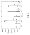
- FIG. 12 is typical biosensor trace of this experiment utilizing the present invention.
- a sequence of five samples consisting of 5 ⁇ l each of analyte sample a 1 , a 2 ; three buffer washes b 1 , b 2 , C 1 , C 2 , d 1 , d 2 ; and a recovery buffer e 1 , e 2 were sequentially brought in contact with the sensor surface, and an oscillatory flow applied in each case.
- the first phase shows the surface binding signal obtained during the capture of the molecules from the analyte sample a 1 to the biosensor surface.
- the signal during the buffer washes b 1 , c 1 , d 1 represents largely the refractive index difference of these buffers.
- a second sequence of application of the samples a 2 to e 2 followed. The purpose of this experiment was to utilize the specific capture of analyte molecules from a sample volume a 1 , a 2 and recovery of the analyte into the recovered volume e 1 , e 2 .
- the recovered volume e 1 and e 2 were then subjected to mass spectrometric analysis of the macromolecular composition allowing the identification of the analyte molecules.
- the oscillatory flow can be applied to the recovery (e) and dissociation can be observed and extended to steady-state.
- Other similar applications of the present invention to concentrate samples using a biosensor or other surface will be apparent to persons skilled in the art.
- the invention can also be used to prepare samples for other analytical experiments, even when only small sample volumes are available.
- the invention is particularly suitable for measuring interactions between analytical molecules in solution with molecules immobilized on a surface or the surfaces itself. These types of interactions may be used to evaluate other properties of molecules or surfaces.
- the invention may be used to measure or assessing conformational changes ofbiomolecules, for example of proteins.
- the microanalytical device in the sample chamber may be a waveguide biosensor. There is also no requirement that molecules in the sample react with particular molecules on the surface of the detector. Rather, the invention may be used to measure the interaction of molecules in the analyte with the surface itself.
- the surface may be, for example, a man-made material.
- a particular application of this use would be the measurement of protein absorption on a man-made surface. This would thus present a method for assessing the biocompatibility of the man made material.
- the invention may be used to measure the interaction of biomolecules with other synthetic or natural molecules.
Landscapes
- Chemical & Material Sciences (AREA)
- Chemical Kinetics & Catalysis (AREA)
- Business, Economics & Management (AREA)
- Health & Medical Sciences (AREA)
- Accounting & Taxation (AREA)
- Dispersion Chemistry (AREA)
- Finance (AREA)
- Analytical Chemistry (AREA)
- General Health & Medical Sciences (AREA)
- Hematology (AREA)
- Clinical Laboratory Science (AREA)
- Economics (AREA)
- Theoretical Computer Science (AREA)
- Strategic Management (AREA)
- Physics & Mathematics (AREA)
- General Business, Economics & Management (AREA)
- General Physics & Mathematics (AREA)
- Engineering & Computer Science (AREA)
- Development Economics (AREA)
- Automatic Analysis And Handling Materials Therefor (AREA)
- Investigating Or Analysing Materials By Optical Means (AREA)
- Apparatus Associated With Microorganisms And Enzymes (AREA)
- Financial Or Insurance-Related Operations Such As Payment And Settlement (AREA)
- Investigating Or Analysing Materials By The Use Of Chemical Reactions (AREA)
- Investigating Or Analysing Biological Materials (AREA)
Claims (22)
- Vorrichtung zur Molekülerfassung, umfassend:eine Probenkammer (3),einen ersten Mikrokanal (14) in Fluidverbindung mit der Probenkammer (3),einen zweiten Mikrokanal (16) in Fluidverbindung mit der Probenkammer (3) undmindestens eine Pumpe (11) zum Erleichtern des Pumpens einer Fluidprobe (12) von dem ersten Mikrokanal (14) durch die Probenkammer (3) und in den zweiten Mikrokanal (16) und von dem zweiten Mikrokanal durch die Probenkammer und in den ersten Mikrokanal, wobeimindestens eines bzw. eine des ersten Mikrokanals (14), der Probenkammer (3) und des zweiten Mikrokanals (16) eine Breite aufweist, die ein molekulares Mischen der Probe durch eine laminare Strömung innerhalb der Fluidprobe verursacht, wenn sich die Fluidprobe durch den bzw. die mindestens einen Mikrokanal und/oder Probenkammer bewegt, und
die Probenkammer (3) einen mikroanalytischen Detektor (7) umfasst. - Vorrichtung nach Anspruch 1, bei der die Mikrokanäle (14, 16) eine Breite von etwa 10 µm bis etwa 1 mm, vorzugsweise von etwa 50 µm bis etwa 500 µm aufweisen.
- Vorrichtung nach Anspruch 1 oder Anspruch 2, bei der die Probenkammer (3) ein Volumen von etwa 1 nl bis etwa 10 µl, vorzugsweise von etwa 10 nl bis etwa 100 nl umfasst.
- Vorrichtung nach einem der vorstehenden Ansprüche, bei welcher der mikroanalytische Detektor (7) so angeordnet ist, dass die Bindungsgeschwindigkeit von Reaktionen zwischen Molekülen, die aus Paaren von Proteinen, Antikörper und Antigenen, Proteinen und Kohlenhydraten, Proteinen und Peptiden, Proteinen und Nukleinsäuren, Paaren von Nukleinsäuren und Molekülen und einer Oberfläche ausgewählt sind, bewertet wird.
- Vorrichtung nach einem der Ansprüche 1 bis 3, bei welcher der mikroanalytische Detektor (7) so angeordnet ist, dass die Gleichgewichtskonstanten von Reaktionen zwischen Molekülen, die aus Paaren von Proteinen, Antikörper und Antigenen, Proteinen und Kohlenhydraten, Proteinen und Peptiden, Proteinen und Nukleinsäuren, Paaren von Nukleinsäuren und Molekülen und einer Oberfläche ausgewählt sind, bewertet wird.
- Vorrichtung nach einem der Ansprüche 1 bis 3, bei welcher der mikroanalytische Detektor (7) so angeordnet ist, dass die Konformationsänderungen von Molekülen bewertet werden.
- Vorrichtung nach einem der Ansprüche 1 bis 3, bei welcher der mikroanalytische Detektor (7) so angeordnet ist, dass die Gleichgewichtskonstanten von biomolekularen Reaktionen zwischen einem Paar von wechselwirkenden oder chemisch reagierenden Molekülen bewertet werden.
- Vorrichtung nach einem der vorstehenden Ansprüche, wobei die Vorrichtung eine Enzymaktivität bewerten kann.
- Vorrichtung nach einem der vorstehenden Ansprüche, bei der die Pumpe (11) eine oszillierende Pumpe umfasst.
- Vorrichtung nach Anspruch 9, bei der die oszillierende Pumpe (11) eine Spritzenpumpe ist.
- Verfahren zur Molekülerfassung, umfassend:Pumpen einer zu analysierenden Fluidprobe (12) durch einen ersten Mikrokanal (14) und eine Probenkammer (3) in einen zweiten Mikrokanal (16), wobei die Probenkammer einen mikroanalytischen Detektor (7) umfasst,Umkehren der Strömung der Fluidprobe (12) derart, dass die Fluidprobe von dem zweiten Mikrokanal (16) in die Probenkammer (3) und dann in den ersten Mikrokanal (14) strömt, und Erfassen eines Signals von dem Detektor (7), wobeidie Probenkammer (3) kontinuierlich mit einem Teil der Fluidprobe (12) gefüllt wird,
mindestens ein Teil sowohl des ersten Mikrokanals (14) als auch des zweiten Mikrokanals (16) kontinuierlich einen Teil der Fluidprobe (12) enthält, und
mindestens einer bzw. eine des ersten Mikrokanals (14), der Probenkammer (3) und des zweiten Mikrokanals (16) eine Breite aufweist, die ein molekulares Mischen durch die laminare Strömung innerhalb der Ftuidprobe (12) verursacht, wenn sich die Fluidprobe durch mindestens eine(n) des Mikrokanals und/oder der Probenkammer bewegt. - Verfahren nach Anspruch 11, bei dem die Fluidprobe (12) ein Volumen von weniger als etwa 20 µl, vorzugsweise von etwa 3 µl bis etwa 8 µl aufweist.
- Verfahren nach Anspruch 11 oder Anspruch 12, das ferner das Ersetzen der Fluidprobe (12) durch einen Puffer und Überwachen eines Signals von dem Detektor (7) umfasst.
- Verfahren nach einem der Ansprüche 11 bis 13, bei dem die Probe (12) zur Bewertung der Bindungsgeschwindigkeiten von Reaktionen zwischen Molekülen, die aus der Gruppe bestehend aus Paaren von Proteinen, Antikörper und Antigenen, Proteinen und Kohlenhydraten, Proteinen und Peptiden, Proteinen und Nukleinsäuren, Paaren von Nukleinsäuren und Molekülen und einer Oberfläche ausgewählt sind, analysiert wird.
- Verfahren nach einem der Ansprüche 11 bis 13, bei dem die Probe (12) zur Bewertung von Gleichgewichtskonstanten von Reaktionen zwischen Molekülen, die aus der Gruppe bestehend aus Paaren von Proteinen, Antikörper und Antigenen, Proteinen und Kohlenhydraten, Proteinen und Peptiden, Proteinen und Nukleinsäuren, Paaren von Nukleinsäuren und Molekülen und einer Oberfläche ausgewählt sind, analysiert wird.
- Verfahren nach einem der Ansprüche 11 bis 13, bei dem die Probe (12) zur Bewertung von Gleichgewichtskonstanten von Reaktionen zwischen einem Paar von wechselwirkenden oder chemisch reagierenden Molekülen analysiert wird.
- Verfahren nach einem der Ansprüche 11 bis 13, bei dem die Probe (12) zur Bewertung von Enzymaktivitäten analysiert wird.
- Verfahren nach einem der Ansprüche 11 bis 13, bei dem Konformationsänderungen in Molekülen gemessen werden.
- Vorrichtung nach Anspruch 6 oder Verfahren nach Anspruch 18, bei der bzw. dem die Moleküle Biomoleküle sind.
- Vorrichtung nach einem der Ansprüche 1 bis 10 und 19 oder Verfahren nach einem der Ansprüche 11 bis 19, bei der bzw. dem der mikroanalytische Detektor (7) einen Biosensor umfasst.
- Vorrichtung oder Verfahren nach Anspruch 20, bei der bzw. dem der Biosensor ein Wellenleiter-Biosensor ist.
- Verfahren zur Bioerfassung, umfassend:Bereitstellen einer Vorrichtung nach einem der Ansprüche 9 und 10,Ansaugen einer ersten Luftblase (13) in die Vorrichtung,Ansaugen einer Fluidprobe (12), die ein Analytmolekül umfasst, in die Vorrichtung,Ansaugen einer zweiten Luftblase (17) in die Vorrichtung,Aktivieren der Pumpe (11), so dass ein Zurück- und Vorströmen der Fluidprobe von dem ersten Mikrokanal (14) zu der Probenkammer (3) und in den zweiten Mikrokanal (16) und von dem zweiten Mikrokanal (16) zu der Probenkammer (3) und in den ersten Mikrokanal (14) verursacht wird, undErfassen eines Signals von dem mikroanalytischen Detektor (7), wobeider mikroanalytische Detektor ein Biosensor (7) ist, mindestens ein Teil der Fluidprobe (12) mit dem Biosensor (7) in Kontakt ist und mindestens ein Teil des ersten und des zweiten Mikrokanals (14, 16) mindestens einen Teil der Fluidprobe enthält.
Applications Claiming Priority (3)
| Application Number | Priority Date | Filing Date | Title |
|---|---|---|---|
| US24555500P | 2000-11-06 | 2000-11-06 | |
| US245555P | 2000-11-06 | ||
| PCT/US2001/042980 WO2002037079A2 (en) | 2000-11-06 | 2001-11-06 | Sample delivery system with laminar mixing for microvolume biosensing |
Publications (3)
| Publication Number | Publication Date |
|---|---|
| EP1339496A2 EP1339496A2 (de) | 2003-09-03 |
| EP1339496A4 EP1339496A4 (de) | 2004-10-27 |
| EP1339496B1 true EP1339496B1 (de) | 2007-02-28 |
Family
ID=22927133
Family Applications (1)
| Application Number | Title | Priority Date | Filing Date |
|---|---|---|---|
| EP01990651A Expired - Lifetime EP1339496B1 (de) | 2000-11-06 | 2001-11-06 | Probenzuführsystem mit laminarmischung zur biodetektion von mikrovolumen |
Country Status (6)
| Country | Link |
|---|---|
| US (1) | US20100114764A1 (de) |
| EP (1) | EP1339496B1 (de) |
| AT (1) | ATE355129T1 (de) |
| AU (1) | AU2002230418A1 (de) |
| DE (1) | DE60126975T2 (de) |
| WO (1) | WO2002037079A2 (de) |
Families Citing this family (11)
| Publication number | Priority date | Publication date | Assignee | Title |
|---|---|---|---|---|
| EP1561507A1 (de) * | 2004-01-27 | 2005-08-10 | Future Diagnostics B.V. | System für das Kennzeichnen einer Flüssigkeit, microfluidische Vorrichtung für das Kennzeichnen oder das Analysieren der Bestandteile einer Konzentration, eine Methode des Kennzeichnens oder des Analysierens solcher Konzentrationen und einer Messvorrichtung |
| US20110196790A1 (en) * | 2010-02-05 | 2011-08-11 | Milne Benjamin P | Transaction processing system |
| US8620805B2 (en) | 2012-03-27 | 2013-12-31 | Citicorp Credit Services, Inc. | Methods and systems for processing payments globally over one of a plurality of processing paths |
| US10380564B1 (en) | 2013-12-05 | 2019-08-13 | Square, Inc. | Merchant performed banking-type transactions |
| US10726410B2 (en) * | 2014-03-31 | 2020-07-28 | Truist Bank | Web page action guidance system |
| US20150363778A1 (en) * | 2014-06-16 | 2015-12-17 | Bank Of America Corporation | Cryptocurrency electronic payment system |
| US10453056B2 (en) * | 2017-06-29 | 2019-10-22 | Square, Inc. | Secure account creation |
| US12321917B2 (en) | 2021-08-27 | 2025-06-03 | Worldpay, Llc | Systems and methods for executing real-time electronic transactions using graphical user interface |
| WO2023133257A1 (en) * | 2022-01-06 | 2023-07-13 | Bangor Bankcorp Mhc | Computer implemented method for dynamically settling payment requests with various funding sources |
| US20240095694A1 (en) * | 2022-09-21 | 2024-03-21 | Step Mobile, Inc. | Dynamically guiding users to request valid payments |
| US20250278708A1 (en) * | 2024-03-04 | 2025-09-04 | The Pnc Financial Services Group, Inc. | Optimizing batch bill payment |
Family Cites Families (22)
| Publication number | Priority date | Publication date | Assignee | Title |
|---|---|---|---|---|
| US5134079A (en) * | 1989-03-27 | 1992-07-28 | International Technidyne Corp. | Fluid sample collection and delivery system and methods particularly adapted for body fluid sampling |
| US5383113A (en) * | 1991-07-25 | 1995-01-17 | Checkfree Corporation | System and method for electronically providing customer services including payment of bills, financial analysis and loans |
| US5268147A (en) * | 1992-02-26 | 1993-12-07 | Miles, Inc. | Reversible direction capsule chemistry sample liquid analysis system and method |
| US5587128A (en) * | 1992-05-01 | 1996-12-24 | The Trustees Of The University Of Pennsylvania | Mesoscale polynucleotide amplification devices |
| DE69429038T2 (de) * | 1993-07-28 | 2002-03-21 | Pe Corporation (Ny), Norwalk | Vorrichtung und Verfahren zur Nukleinsäurevervielfältigung |
| US6001229A (en) * | 1994-08-01 | 1999-12-14 | Lockheed Martin Energy Systems, Inc. | Apparatus and method for performing microfluidic manipulations for chemical analysis |
| US5658413A (en) * | 1994-10-19 | 1997-08-19 | Hewlett-Packard Company | Miniaturized planar columns in novel support media for liquid phase analysis |
| US5716852A (en) * | 1996-03-29 | 1998-02-10 | University Of Washington | Microfabricated diffusion-based chemical sensor |
| US6130098A (en) * | 1995-09-15 | 2000-10-10 | The Regents Of The University Of Michigan | Moving microdroplets |
| US5726404A (en) * | 1996-05-31 | 1998-03-10 | University Of Washington | Valveless liquid microswitch |
| US5897621A (en) * | 1996-06-14 | 1999-04-27 | Cybercash, Inc. | System and method for multi-currency transactions |
| US6447727B1 (en) * | 1996-11-19 | 2002-09-10 | Caliper Technologies Corp. | Microfluidic systems |
| AU6036998A (en) * | 1997-01-24 | 1998-08-18 | Regents Of The University Of California, The | Apparatus and method for planar laminar mixing |
| WO1998049548A1 (en) * | 1997-04-25 | 1998-11-05 | Caliper Technologies Corporation | Microfluidic devices incorporating improved channel geometries |
| US6128603A (en) * | 1997-09-09 | 2000-10-03 | Dent; Warren T. | Consumer-based system and method for managing and paying electronic billing statements |
| US6274089B1 (en) * | 1998-06-08 | 2001-08-14 | Caliper Technologies Corp. | Microfluidic devices, systems and methods for performing integrated reactions and separations |
| US6008893A (en) * | 1999-03-22 | 1999-12-28 | Biacore Ab | Reversible-flow conduit system |
| US6375817B1 (en) * | 1999-04-16 | 2002-04-23 | Perseptive Biosystems, Inc. | Apparatus and methods for sample analysis |
| AU7808800A (en) * | 1999-10-20 | 2001-04-30 | University Of Sheffield, The | Fluidic mixer |
| US6999943B1 (en) * | 2000-03-10 | 2006-02-14 | Doublecredit.Com, Inc. | Routing methods and systems for increasing payment transaction volume and profitability |
| WO2001089691A2 (en) * | 2000-05-24 | 2001-11-29 | Micronics, Inc. | Capillaries for fluid movement within microfluidic channels |
| US7110980B2 (en) * | 2002-06-21 | 2006-09-19 | American Express Bank Ltd. | System and method for facilitating electronic transfer of funds |
-
2001
- 2001-11-06 EP EP01990651A patent/EP1339496B1/de not_active Expired - Lifetime
- 2001-11-06 AT AT01990651T patent/ATE355129T1/de not_active IP Right Cessation
- 2001-11-06 WO PCT/US2001/042980 patent/WO2002037079A2/en not_active Ceased
- 2001-11-06 DE DE60126975T patent/DE60126975T2/de not_active Expired - Lifetime
- 2001-11-06 AU AU2002230418A patent/AU2002230418A1/en not_active Abandoned
-
2009
- 2009-10-27 US US12/606,348 patent/US20100114764A1/en not_active Abandoned
Also Published As
| Publication number | Publication date |
|---|---|
| DE60126975T2 (de) | 2007-11-15 |
| US20100114764A1 (en) | 2010-05-06 |
| WO2002037079A2 (en) | 2002-05-10 |
| WO2002037079A3 (en) | 2002-08-29 |
| EP1339496A2 (de) | 2003-09-03 |
| ATE355129T1 (de) | 2006-03-15 |
| AU2002230418A1 (en) | 2002-05-15 |
| EP1339496A4 (de) | 2004-10-27 |
| DE60126975D1 (de) | 2007-04-12 |
Similar Documents
| Publication | Publication Date | Title |
|---|---|---|
| US9316636B2 (en) | Method and system for determination of molecular interaction parameters | |
| AU768861B2 (en) | Reversible-flow conduit system | |
| EP1021703B1 (de) | Verfahren und vorrichtung zur laminaren strömung an einer sensoroberfläche | |
| US7642058B2 (en) | Method and apparatus for characterization of interactions | |
| EP1631824B1 (de) | Verfahren und system zur bestimmung molekularer wechselwirkungsparameter | |
| EP1339496B1 (de) | Probenzuführsystem mit laminarmischung zur biodetektion von mikrovolumen | |
| US20040028559A1 (en) | Sample delivery system with laminar mixing for microvolume biosensing | |
| US20200103343A1 (en) | Measuring System, Such as an Interaction Measuring System and a Measuring Method | |
| EP1688179B1 (de) | Vorrichtung zur Dissoziationskonstantenmessung | |
| EP1631829A1 (de) | Verfahren und vorrichtung zur charakterisierung von wechselwirkungen | |
| US20250354927A1 (en) | Surface plasmon resonance measuring system and a method for surface plasmon resonance measurement for injection of samples using a cuvette-injection-flow system |
Legal Events
| Date | Code | Title | Description |
|---|---|---|---|
| PUAI | Public reference made under article 153(3) epc to a published international application that has entered the european phase |
Free format text: ORIGINAL CODE: 0009012 |
|
| 17P | Request for examination filed |
Effective date: 20030523 |
|
| AK | Designated contracting states |
Kind code of ref document: A2 Designated state(s): AT BE CH CY DE DK ES FI FR GB GR IE IT LI LU MC NL PT SE TR |
|
| AX | Request for extension of the european patent |
Extension state: AL LT LV MK RO SI |
|
| A4 | Supplementary search report drawn up and despatched |
Effective date: 20040909 |
|
| 17Q | First examination report despatched |
Effective date: 20050224 |
|
| GRAP | Despatch of communication of intention to grant a patent |
Free format text: ORIGINAL CODE: EPIDOSNIGR1 |
|
| GRAS | Grant fee paid |
Free format text: ORIGINAL CODE: EPIDOSNIGR3 |
|
| GRAA | (expected) grant |
Free format text: ORIGINAL CODE: 0009210 |
|
| AK | Designated contracting states |
Kind code of ref document: B1 Designated state(s): AT BE CH CY DE DK ES FI FR GB GR IE IT LI LU MC NL PT SE TR |
|
| PG25 | Lapsed in a contracting state [announced via postgrant information from national office to epo] |
Ref country code: LI Free format text: LAPSE BECAUSE OF FAILURE TO SUBMIT A TRANSLATION OF THE DESCRIPTION OR TO PAY THE FEE WITHIN THE PRESCRIBED TIME-LIMIT Effective date: 20070228 Ref country code: NL Free format text: LAPSE BECAUSE OF FAILURE TO SUBMIT A TRANSLATION OF THE DESCRIPTION OR TO PAY THE FEE WITHIN THE PRESCRIBED TIME-LIMIT Effective date: 20070228 Ref country code: AT Free format text: LAPSE BECAUSE OF FAILURE TO SUBMIT A TRANSLATION OF THE DESCRIPTION OR TO PAY THE FEE WITHIN THE PRESCRIBED TIME-LIMIT Effective date: 20070228 Ref country code: CH Free format text: LAPSE BECAUSE OF FAILURE TO SUBMIT A TRANSLATION OF THE DESCRIPTION OR TO PAY THE FEE WITHIN THE PRESCRIBED TIME-LIMIT Effective date: 20070228 Ref country code: FI Free format text: LAPSE BECAUSE OF FAILURE TO SUBMIT A TRANSLATION OF THE DESCRIPTION OR TO PAY THE FEE WITHIN THE PRESCRIBED TIME-LIMIT Effective date: 20070228 Ref country code: DK Free format text: LAPSE BECAUSE OF FAILURE TO SUBMIT A TRANSLATION OF THE DESCRIPTION OR TO PAY THE FEE WITHIN THE PRESCRIBED TIME-LIMIT Effective date: 20070228 Ref country code: BE Free format text: LAPSE BECAUSE OF FAILURE TO SUBMIT A TRANSLATION OF THE DESCRIPTION OR TO PAY THE FEE WITHIN THE PRESCRIBED TIME-LIMIT Effective date: 20070228 |
|
| REG | Reference to a national code |
Ref country code: GB Ref legal event code: FG4D |
|
| REG | Reference to a national code |
Ref country code: CH Ref legal event code: EP |
|
| REF | Corresponds to: |
Ref document number: 60126975 Country of ref document: DE Date of ref document: 20070412 Kind code of ref document: P |
|
| REG | Reference to a national code |
Ref country code: IE Ref legal event code: FG4D |
|
| PG25 | Lapsed in a contracting state [announced via postgrant information from national office to epo] |
Ref country code: SE Free format text: LAPSE BECAUSE OF FAILURE TO SUBMIT A TRANSLATION OF THE DESCRIPTION OR TO PAY THE FEE WITHIN THE PRESCRIBED TIME-LIMIT Effective date: 20070531 |
|
| PG25 | Lapsed in a contracting state [announced via postgrant information from national office to epo] |
Ref country code: ES Free format text: LAPSE BECAUSE OF FAILURE TO SUBMIT A TRANSLATION OF THE DESCRIPTION OR TO PAY THE FEE WITHIN THE PRESCRIBED TIME-LIMIT Effective date: 20070608 |
|
| PG25 | Lapsed in a contracting state [announced via postgrant information from national office to epo] |
Ref country code: PT Free format text: LAPSE BECAUSE OF FAILURE TO SUBMIT A TRANSLATION OF THE DESCRIPTION OR TO PAY THE FEE WITHIN THE PRESCRIBED TIME-LIMIT Effective date: 20070730 |
|
| NLV1 | Nl: lapsed or annulled due to failure to fulfill the requirements of art. 29p and 29m of the patents act | ||
| ET | Fr: translation filed | ||
| REG | Reference to a national code |
Ref country code: CH Ref legal event code: PL |
|
| PLBE | No opposition filed within time limit |
Free format text: ORIGINAL CODE: 0009261 |
|
| STAA | Information on the status of an ep patent application or granted ep patent |
Free format text: STATUS: NO OPPOSITION FILED WITHIN TIME LIMIT |
|
| 26N | No opposition filed |
Effective date: 20071129 |
|
| PG25 | Lapsed in a contracting state [announced via postgrant information from national office to epo] |
Ref country code: IT Free format text: LAPSE BECAUSE OF FAILURE TO SUBMIT A TRANSLATION OF THE DESCRIPTION OR TO PAY THE FEE WITHIN THE PRESCRIBED TIME-LIMIT Effective date: 20070228 Ref country code: GR Free format text: LAPSE BECAUSE OF FAILURE TO SUBMIT A TRANSLATION OF THE DESCRIPTION OR TO PAY THE FEE WITHIN THE PRESCRIBED TIME-LIMIT Effective date: 20070529 |
|
| PG25 | Lapsed in a contracting state [announced via postgrant information from national office to epo] |
Ref country code: MC Free format text: LAPSE BECAUSE OF NON-PAYMENT OF DUE FEES Effective date: 20071130 |
|
| PG25 | Lapsed in a contracting state [announced via postgrant information from national office to epo] |
Ref country code: IE Free format text: LAPSE BECAUSE OF NON-PAYMENT OF DUE FEES Effective date: 20071106 |
|
| PG25 | Lapsed in a contracting state [announced via postgrant information from national office to epo] |
Ref country code: CY Free format text: LAPSE BECAUSE OF FAILURE TO SUBMIT A TRANSLATION OF THE DESCRIPTION OR TO PAY THE FEE WITHIN THE PRESCRIBED TIME-LIMIT Effective date: 20070228 |
|
| PG25 | Lapsed in a contracting state [announced via postgrant information from national office to epo] |
Ref country code: LU Free format text: LAPSE BECAUSE OF NON-PAYMENT OF DUE FEES Effective date: 20071106 |
|
| PG25 | Lapsed in a contracting state [announced via postgrant information from national office to epo] |
Ref country code: TR Free format text: LAPSE BECAUSE OF FAILURE TO SUBMIT A TRANSLATION OF THE DESCRIPTION OR TO PAY THE FEE WITHIN THE PRESCRIBED TIME-LIMIT Effective date: 20070228 |
|
| PGFP | Annual fee paid to national office [announced via postgrant information from national office to epo] |
Ref country code: DE Payment date: 20101126 Year of fee payment: 10 |
|
| PGFP | Annual fee paid to national office [announced via postgrant information from national office to epo] |
Ref country code: GB Payment date: 20101124 Year of fee payment: 10 |
|
| PGFP | Annual fee paid to national office [announced via postgrant information from national office to epo] |
Ref country code: FR Payment date: 20111128 Year of fee payment: 11 |
|
| GBPC | Gb: european patent ceased through non-payment of renewal fee |
Effective date: 20121106 |
|
| REG | Reference to a national code |
Ref country code: FR Ref legal event code: ST Effective date: 20130731 |
|
| REG | Reference to a national code |
Ref country code: DE Ref legal event code: R119 Ref document number: 60126975 Country of ref document: DE Effective date: 20130601 |
|
| PG25 | Lapsed in a contracting state [announced via postgrant information from national office to epo] |
Ref country code: DE Free format text: LAPSE BECAUSE OF NON-PAYMENT OF DUE FEES Effective date: 20130601 |
|
| PG25 | Lapsed in a contracting state [announced via postgrant information from national office to epo] |
Ref country code: GB Free format text: LAPSE BECAUSE OF NON-PAYMENT OF DUE FEES Effective date: 20121106 Ref country code: FR Free format text: LAPSE BECAUSE OF NON-PAYMENT OF DUE FEES Effective date: 20121130 |