EP1339559B1 - Kraftfahrzeug und verfahren zu dessen antrieb - Google Patents
Kraftfahrzeug und verfahren zu dessen antrieb Download PDFInfo
- Publication number
- EP1339559B1 EP1339559B1 EP01981233A EP01981233A EP1339559B1 EP 1339559 B1 EP1339559 B1 EP 1339559B1 EP 01981233 A EP01981233 A EP 01981233A EP 01981233 A EP01981233 A EP 01981233A EP 1339559 B1 EP1339559 B1 EP 1339559B1
- Authority
- EP
- European Patent Office
- Prior art keywords
- wheels
- axle
- driving
- torque
- vehicle
- Prior art date
- Legal status (The legal status is an assumption and is not a legal conclusion. Google has not performed a legal analysis and makes no representation as to the accuracy of the status listed.)
- Expired - Lifetime
Links
- 238000000034 method Methods 0.000 title claims description 12
- 230000001133 acceleration Effects 0.000 claims description 4
- 230000008901 benefit Effects 0.000 description 2
- 230000006641 stabilisation Effects 0.000 description 2
- 238000011105 stabilization Methods 0.000 description 2
- 230000002411 adverse Effects 0.000 description 1
- 230000005540 biological transmission Effects 0.000 description 1
- 238000010586 diagram Methods 0.000 description 1
- 230000005484 gravity Effects 0.000 description 1
- 230000002452 interceptive effect Effects 0.000 description 1
Images
Classifications
-
- B—PERFORMING OPERATIONS; TRANSPORTING
- B60—VEHICLES IN GENERAL
- B60K—ARRANGEMENT OR MOUNTING OF PROPULSION UNITS OR OF TRANSMISSIONS IN VEHICLES; ARRANGEMENT OR MOUNTING OF PLURAL DIVERSE PRIME-MOVERS IN VEHICLES; AUXILIARY DRIVES FOR VEHICLES; INSTRUMENTATION OR DASHBOARDS FOR VEHICLES; ARRANGEMENTS IN CONNECTION WITH COOLING, AIR INTAKE, GAS EXHAUST OR FUEL SUPPLY OF PROPULSION UNITS IN VEHICLES
- B60K28/00—Safety devices for propulsion-unit control, specially adapted for, or arranged in, vehicles, e.g. preventing fuel supply or ignition in the event of potentially dangerous conditions
- B60K28/10—Safety devices for propulsion-unit control, specially adapted for, or arranged in, vehicles, e.g. preventing fuel supply or ignition in the event of potentially dangerous conditions responsive to conditions relating to the vehicle
- B60K28/16—Safety devices for propulsion-unit control, specially adapted for, or arranged in, vehicles, e.g. preventing fuel supply or ignition in the event of potentially dangerous conditions responsive to conditions relating to the vehicle responsive to, or preventing, spinning or skidding of wheels
- B60K28/165—Safety devices for propulsion-unit control, specially adapted for, or arranged in, vehicles, e.g. preventing fuel supply or ignition in the event of potentially dangerous conditions responsive to conditions relating to the vehicle responsive to, or preventing, spinning or skidding of wheels acting on elements of the vehicle drive train other than the propulsion unit and brakes, e.g. transmission, clutch, differential
-
- B—PERFORMING OPERATIONS; TRANSPORTING
- B60—VEHICLES IN GENERAL
- B60K—ARRANGEMENT OR MOUNTING OF PROPULSION UNITS OR OF TRANSMISSIONS IN VEHICLES; ARRANGEMENT OR MOUNTING OF PLURAL DIVERSE PRIME-MOVERS IN VEHICLES; AUXILIARY DRIVES FOR VEHICLES; INSTRUMENTATION OR DASHBOARDS FOR VEHICLES; ARRANGEMENTS IN CONNECTION WITH COOLING, AIR INTAKE, GAS EXHAUST OR FUEL SUPPLY OF PROPULSION UNITS IN VEHICLES
- B60K17/00—Arrangement or mounting of transmissions in vehicles
- B60K17/34—Arrangement or mounting of transmissions in vehicles for driving both front and rear wheels, e.g. four wheel drive vehicles
- B60K17/348—Arrangement or mounting of transmissions in vehicles for driving both front and rear wheels, e.g. four wheel drive vehicles having differential means for driving one set of wheels, e.g. the front, at one speed and the other set, e.g. the rear, at a different speed
- B60K17/35—Arrangement or mounting of transmissions in vehicles for driving both front and rear wheels, e.g. four wheel drive vehicles having differential means for driving one set of wheels, e.g. the front, at one speed and the other set, e.g. the rear, at a different speed including arrangements for suppressing or influencing the power transfer, e.g. viscous clutches
-
- B—PERFORMING OPERATIONS; TRANSPORTING
- B60—VEHICLES IN GENERAL
- B60K—ARRANGEMENT OR MOUNTING OF PROPULSION UNITS OR OF TRANSMISSIONS IN VEHICLES; ARRANGEMENT OR MOUNTING OF PLURAL DIVERSE PRIME-MOVERS IN VEHICLES; AUXILIARY DRIVES FOR VEHICLES; INSTRUMENTATION OR DASHBOARDS FOR VEHICLES; ARRANGEMENTS IN CONNECTION WITH COOLING, AIR INTAKE, GAS EXHAUST OR FUEL SUPPLY OF PROPULSION UNITS IN VEHICLES
- B60K23/00—Arrangement or mounting of control devices for vehicle transmissions, or parts thereof, not otherwise provided for
- B60K23/08—Arrangement or mounting of control devices for vehicle transmissions, or parts thereof, not otherwise provided for for changing number of driven wheels, for switching from driving one axle to driving two or more axles
- B60K23/0808—Arrangement or mounting of control devices for vehicle transmissions, or parts thereof, not otherwise provided for for changing number of driven wheels, for switching from driving one axle to driving two or more axles for varying torque distribution between driven axles, e.g. by transfer clutch
Definitions
- the invention relates partly to a method for driving a motor vehicle, according to the preamble of claim 1, and partly to a motor vehicle, according to the preamble of claim 8.
- a general problem in motor vehicles of the passenger car type is how to achieve good stability and performance together with safe handling of the vehicle in different driving situations and in all road conditions. It is becoming increasingly more common, therefore, to provide vehicles with various types of traction control, which is intended to prevent the drive wheels from slipping on the road surface, thereby adversely affecting the stability of the vehicle. It is also becoming increasingly more common to provide the vehicle with the facility for driving all four wheels in order to improve further the performance and driving safety in different road conditions.
- a common method of counteracting wheel slip in the case of a driving wheel is to use the vehicle braking system in such instances in order to brake the wheel in question to the necessary extent.
- Vehicles are furthermore provided with various types of electronic stabilization systems, in which the movement of the vehicle is registered by various sensors and the driver is aided by a control system, which on the basis of signals from the said sensors automatically adjusts the brake force acting on different wheels in order to stabilize the handling of the vehicle.
- a torque distribution control system of a four wheel drive system is known from US 5 742 917 A, which discloses all features of the preamble of claims 1 and 8.
- the object of the invention is to improve the driving of a vehicle with four-wheel drive, without unnecessary energy losses.
- Yet another object is to achieve an appropriate distribution of tractive effort between the different wheels of the vehicle by simple means.
- a further object is to make driving easier for the driver in various situations.
- the object of the invention is achieved partly by means of a method having the characteristics specified in claim 1, and partly by means of a motor vehicle having the characteristics specified in claim 8.
- control system it is furthermore possible, by means of the control system, to influence and select various driving characteristics of the vehicle, such as selecting between oversteer and understeer in different situations, for example.
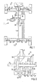
- a motor vehicle 1 according to the invention shown in fig. 1 is provided with a front-mounted engine 2 for driving two front wheels 3, 4 and two rear wheels 5, 6.
- the engine 2 is connected by way of a gearbox 7 and a first drive shaft 8 emerging therefrom to a differential 10 fitted to the front axle 9 of the vehicle, the differential in turn driving the front wheels 3, 4 by way of shafts 11, 12.
- the rear wheels 5, 6 are also driven by way of a second drive shaft 13, which is connected to a final drive unit 14, which is connected to the rear wheels 5, 6 by way of shafts 15, 16 and clutches that form part of the rear axle 17 of the vehicle.
- a steering wheel angle sensor 22 arranged on the vehicle's steering wheel 21 and an accelerator pedal sensor 23, which is arranged on the vehicle's accelerator and which registers the magnitude of the torque that the driver requires from the engine are connected to the control unit 18, as are also a lateral acceleration sensor 24 fitted in the vehicle and a yaw velocity sensor 25.
- the lateral acceleration sensor 24 and the yaw velocity sensor 25 are best fitted close to the normal location of the vehicle's center of gravity 26, in order to provide the most accurate possible information on the movement of the vehicle.
- control system 18 receives information on the current driving situation and on the basis of this is able to calculate the vehicle movement desired by the driver, as when cornering, for example.
- the control unit 18 can in turn act upon the engine 2, the differential 10 and the final drive unit 14, and can control these so that the vehicle behaves safely in a well-controlled manner and utilizes the prevailing road adhesion well.
- differential 10 The specific embodiment of a suitable type of differential 10 is shown diagrammatically in fig 2, but differently constructed differentials of other designs are also conceivable.
- the differential 10 shown is of a type known in the art, which is marketed by the company Mitsubishi Motors under the name "Torque transfer differential".
- a housing 30 contains a differential unit 31 of conventional type, by way of which the first drive shaft 8 drives the second drive shaft 13 and the two shafts 11, 12 to the front wheels 3, 4.
- the shafts 11, 12 can thereby rotate at different speeds when cornering, for example.
- a clutch element 32 is arranged on the shaft 12, this element serving to increase or reduce the rotational speed of the shaft 12 in relation to the speed of the shaft 11, with the aim of varying the torque distribution between these shafts.
- the precise embodiment of a suitable type of final drive unit 14 is shown in diagrammatic form in fig. 3, but differently constructed final drives of other designs are also conceivable.
- the final drive unit 14 shown is of a type known in the art, which is marketed by the company Borg Warner under the name "Interactive Torque Management II" (ITM II).
- Supported in a housing 40 is a shaft 41, which is driven by the second drive shaft 13 by way of a gear.
- the shaft 41 is connected by way of slip clutches 42, 43 to the shafts 15, 16 respectively.
- the said slip clutches are operated and controlled electro-hydraulically in a manner not shown in further detail here, by way of a line 44 from the control unit 18.
- the torque from the second drive shaft 13 can be distributed as required to the two rear wheels 5, 6.
- the gearing for the second drive shaft 13 be selected so that it rotates faster than the shafts 15, 16, that is to say so that the slip is positive and the torque is directed in the same direction as in the first drive shaft 8.
- the drive is connected to one of the wheels 3, 4 on the front axle 9 at all times, whereas it is possible to select when and how the rear axle 17 and its wheels 5, 6 are to be connected.
- This makes it possible to distribute the torque efficiently between different wheels of the vehicle in proportion to the current traction of the various wheels in different driving situations.
- the traction of a wheel is determined here, for example, by the road surface, wheel load, lateral force, etc.
- the control unit 18 obtains information on how the vehicle and its various wheels perform in a given situation and knows, from the information, such as the amount of throttle and steering wheel angle, which is fed in as the driver maneuvers the vehicle, how the driver wishes the vehicle to perform. In this way the control unit 18 can determine the current forces acting on each wheel and can adjust the torque on each wheel so as to get the optimum traction and performance from the vehicle. It is thereby no longer necessary, as previously, to bring about the braking of one wheel in order to limit the torque when wheel slip occurs in slippery conditions, for example. Instead, the available torque can be redistributed between the wheels in order to achieve optimum propulsion. Here, it may be necessary in difficult road conditions to limit the total available torque by reducing the engine throttle. This can best be done automatically by means of the control unit 18.
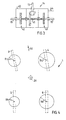
- FIG. 4 An example of a driving situation with different wheel loading is shown in fig. 4, in which in the drawing a motor vehicle 1 is travelling in the direction of the arrow 50 on a left-hand bend.
- the two front wheels 3, 4 are here swiveled at a certain angle to the left by a turn of the steering wheel in order to steer the vehicle on a left-hand bend.
- the vehicle has a tendency to lean outwards on the bend so that the load on the outer wheels 4, 6 increases and the load on the inner wheels 3, 5 diminishes.
- the degree of inclination of the vehicle depends, among other things, on the speed of the vehicle and the radius of the bend.
- the wheel load is here represented by circles on the various wheels, the size of the radii R3, R4, R5, R6 of the circles representing the magnitude of the wheel load on each wheel. In this case the wheel load diminishes in the wheel order 4, 6, 3 and 5. The wheel load is therefore greatest on the front-right wheel 4 and smallest on the rear-left wheel 5.
- the occurrence of a lateral force on a wheel in a known manner limits the tractive effort that can be obtained on a wheel for a given coefficient of friction with the road surface, something which the control unit 18 is continuously analyzing whilst underway.
- the control unit 18 is also keeping track of when the various wheels begin to spin free of the road surface and in this way can determine the magnitude of the torque that can be delivered to each wheel without slipping.
- the drive needs to be connected to the rear wheels only when strong acceleration is required, but normally the drive to the rear wheels can be disengaged.
- the control unit 18 here determines when to engage and disengage the drive. Similarly the control unit 18 monitors what drive is required to the various wheels in other driving situations.
- control unit 18 Through suitable programming of the control unit 18 it is also possible to give the vehicle special handling characteristics and thereby to select how the vehicle will perform in different driving situations. It is possible, for example, by boosting the torque to the outer wheels, to make a vehicle that normally understeers less susceptible to understeer in special situations. Many other possibilities relating to torque distribution are available here within the scope of the invention, depending on needs and requirements. It is thus possible to make the work of the driver easier, and the vehicle safer.
- the description above relates basically to a front-wheel drive car with front-mounted engine.
- the opposite case is also conceivable, that is to say an essentially rear-wheel drive car in which the differential 10 is fitted to the rear axle and the final drive 14 to the front axle.
Landscapes
- Engineering & Computer Science (AREA)
- Chemical & Material Sciences (AREA)
- Combustion & Propulsion (AREA)
- Transportation (AREA)
- Mechanical Engineering (AREA)
- Arrangement And Driving Of Transmission Devices (AREA)
- Hybrid Electric Vehicles (AREA)
- Types And Forms Of Lifts (AREA)
- Load-Engaging Elements For Cranes (AREA)
- Forklifts And Lifting Vehicles (AREA)
- Paper (AREA)
Claims (17)
- Verfahren zum Antreiben eines Kraftfahrzeugs mit vier antreibbaren Rädern (3-6), zwei an einer Vorderachse (9) und zwei an einer Hinterachse (17), bei dem Motordrehmoment im Fluss auf verschiedene Räder im Hinblick auf die an diesen Rädern vorherrschende Straßenhaftung verteilt wird,
dadurch gekennzeichnet, dass in einer gegebenen aktuellen Fahrsituation ermittelt wird, an welchem der vier Räder (3-6) ein Antreiben erforderlich oder möglich ist, ein Antreiben der Räder an der Vorder- (9) oder der Hinterachse (17) in Abhängigkeit dieser Situation priorisiert wird und nur dann, wenn ein Antreiben von Rädern an nur einer dieser Achsen unzureichend ist, ein Antreiben von Rädern auch an der anderen Achse ausgewählt wird, und dann, wenn Räder auch an der anderen Achse angetrieben werden, ein erforderliches oder gewünschtes Drehmoment auf die Räder an dieser Achse im Hinblick auf die an diesen Rädern vorherrschende Straßenhaftung verteilt wird. - Verfahren nach Anspruch 1,
dadurch gekennzeichnet, dass ein an der priorisierten Achse erforderliches oder gewünschtes Drehmoment auf die Räder an dieser Achse im Hinblick auf die an diesen Rädern vorherrschende Straßenhaftung verteilt wird. - Verfahren nach Anspruch 1,
dadurch gekennzeichnet, dass das Antreiben der Räder an der Vorderachse (9) priorisiert wird. - Verfahren nach einem der Ansprüche 1 bis 3,
dadurch gekennzeichnet, dass im Fall einer relativen Änderung der vorherrschenden Straßenhaftung an verschiedenen Rädern eine Neuverteilung des Drehmoments auf die Räder erfolgt. - Verfahren nach einem der Ansprüche 1 bis 4,
dadurch gekennzeichnet, dass die Neuverteilung des Drehmoments auf die Räder ohne einen Bremsvorgang an einem Rad erfolgt. - Verfahren nach einem der Ansprüche 1 bis 5,
dadurch gekennzeichnet, dass die an verschiedenen Rädern vorherrschende Straßenhaftung bestimmt wird auf der Grundlage, wie sich das Fahrzeug bewegt und wie sich die Räder drehen. - Verfahren nach einem der Ansprüche 1 bis 6,
dadurch gekennzeichnet, dass eine in dem Fahrzeug angeordnete Steuereinheit (18) überwacht, ob das durch den Fahrer angeforderte Drehmoment für die aktuelle Fahrsituation unzulässig hoch ist, und dass die Steuereinheit das Drehmoment durch Reduzierung der Drosselklappe des Motors (2) auf ein zulässiges Niveau verringert, wenn das angeforderte Drehmoment unzulässig hoch ist. - Kraftfahrzeug mit vier antreibbaren Rädern (3-6), zwei an einer Vorderachse (9) und zwei an einer Hinterachse (17), wobei in dem Fahrzeug eine Steuereinheit (18) vorhanden ist, die durch verschiedene Sensoren (19, 20, 22-25) an dem Fahrzeug Informationen über die aktuelle Fahrsituation erhält und die dazu eingerichtet ist, auf der Basis der von den Sensoren erhaltenen Informationen Steuersignale an an dem Fahrzeug angeordnete Steuerelemente (2, 10, 14) zu senden, um ein Motordrehmoment auf verschiedene Räder im Hinblick auf die an diesen Rädern vorherrschende Straßenhaftung zu verteilen,
dadurch gekennzeichnet, dass die Steuereinheit (18) dazu eingerichtet ist, unterwegs in einer gegebenen aktuellen Fahrsituation zu bestimmen, an welchem der vier Räder ein Antreiben erforderlich oder möglich ist, und ein Antreiben von Rädern entweder an der Vorderachse oder der Hinterachse zu priorisieren und ein Antreiben von Rädern auch an der anderen Achse nur dann zu auswählen, wenn ein Antreiben der Räder an nur einer der Achsen unzureichend ist, und dann, wenn ein Antreiben der Räder auch an der anderen Achse ausgewählt wird, ein an dieser Achse erforderliches oder gewünschtes Drehmoment auf die Räder an dieser Achse im Hinblick auf die an diesen Rädern vorherrschende Straßenhaftung zu verteilen. - Kraftfahrzeug nach Anspruch 8,
dadurch gekennzeichnet, dass die Steuereinheit (18) dazu eingerichtet ist, ein an der priorisierten Achse erforderliches oder gewünschtes Drehmoment auf die Räder an dieser Achse im Hinblick auf die an diesen Rädern vorherrschende Straßenhaftung zu verteilen. - Kraftfahrzeug nach Anspruch 9,
dadurch gekennzeichnet, dass das Steuersystem dazu eingerichtet ist, das Antreiben der Räder an der Vorderachse (9) zu priorisieren. - Kraftfahrzeug nach Anspruch 10,
dadurch gekennzeichnet, dass die Vorderachse (9) des Fahrzeugs mit einem Differential (10) versehen ist, das durch eine erste Antriebswelle (8) mit dem Motor (2) verbunden und so gestaltet ist, dass es dazu in der Lage ist, ein Eingangsdrehmoment von dem Motor auf die Vorderräder (3, 4) des Fahrzeugs im Verhältnis zu der an diesen Rädern vorherrschenden Straßenhaftung zu verteilen. - Kraftfahrzeug nach Anspruch 11,
dadurch gekennzeichnet, dass sich eine zweite Antriebswelle (13) zum Antreiben der Hinterräder (5, 6) des Fahrzeugs aus dem Differential (10) erstreckt und dass die zweite Antriebswelle (13) durch eine Achsantriebseinheit (14) mit den Hinterrädern verbunden ist. - Kraftfahrzeug nach Anspruch 12,
dadurch gekennzeichnet, dass die Achsantriebseinheit (14) zwei Kupplungen (42, 43) umfasst, die jeweils mit einem Hinterrad (5, 6) verbunden und dazu eingerichtet sind, Drehmoment auf jedes Rad im Verhältnis zu dem Maß an Eingriff in der betreffenden Kupplung zu übertragen. - Kraftfahrzeug nach Anspruch 13,
dadurch gekennzeichnet, dass die Übersetzung für die zweite Antriebswelle (13) so gewählt ist, dass sich die zweite Antriebswelle schneller dreht als die Wellen (15, 16) zu den Hinterrädern (5, 6), so dass das Drehmoment in der gleichen Richtung gerichtet ist, wie an der ersten Antriebswelle (8). - Kraftfahrzeug nach einem der Ansprüche 8 bis 14,
dadurch gekennzeichnet, dass ein Lenkradwinkelsensor (22) und ein Gaspedalsensor (23) mit der Steuereinheit (18) verbunden sind, um während der Fahrt die Absichten des Fahrers einzugeben. - Kraftfahrzeug nach einem der Ansprüche 8 bis 15,
dadurch gekennzeichnet, dass mindestens einer der folgenden Typen von Sensoren mit der Steuereinheit (18) verbunden ist: Raddrehzahlsensor (19), Raddrehmomentsensor, Niveausensor (20), Querbeschleunigungssensor (24) und Gierwinkelsensor (25) zum Eingeben des aktuellen Verhaltens des Fahrzeugs in die Steuereinheit. - Kraftfahrzeug nach einem der Ansprüche 8 bis 16,
dadurch gekennzeichnet, dass die Steuereinheit (18) zum Steuern des vom Motor (2) gelieferten Drehmoments mit letzterem verbunden ist.
Applications Claiming Priority (3)
| Application Number | Priority Date | Filing Date | Title |
|---|---|---|---|
| SE0003976 | 2000-10-31 | ||
| SE0003976A SE519300C2 (sv) | 2000-10-31 | 2000-10-31 | Motorfordon med fyra drivbara hjul samt sätt att driva detta |
| PCT/SE2001/002376 WO2002036383A1 (en) | 2000-10-31 | 2001-10-30 | Motor vehicle and a method for propelling the same |
Publications (2)
| Publication Number | Publication Date |
|---|---|
| EP1339559A1 EP1339559A1 (de) | 2003-09-03 |
| EP1339559B1 true EP1339559B1 (de) | 2005-02-09 |
Family
ID=20281649
Family Applications (1)
| Application Number | Title | Priority Date | Filing Date |
|---|---|---|---|
| EP01981233A Expired - Lifetime EP1339559B1 (de) | 2000-10-31 | 2001-10-30 | Kraftfahrzeug und verfahren zu dessen antrieb |
Country Status (6)
| Country | Link |
|---|---|
| EP (1) | EP1339559B1 (de) |
| AT (1) | ATE288841T1 (de) |
| AU (1) | AU2002212890A1 (de) |
| DE (1) | DE60108896T2 (de) |
| SE (1) | SE519300C2 (de) |
| WO (1) | WO2002036383A1 (de) |
Families Citing this family (3)
| Publication number | Priority date | Publication date | Assignee | Title |
|---|---|---|---|---|
| DE10312879A1 (de) * | 2003-03-22 | 2004-10-07 | Bayerische Motoren Werke Ag | Steuersystem zur variablen Drehmomentverteilung |
| JP4229193B2 (ja) * | 2007-04-06 | 2009-02-25 | 三菱自動車工業株式会社 | 車両用差動制限装置 |
| DE102017212650B4 (de) * | 2017-07-24 | 2019-02-28 | Magna powertrain gmbh & co kg | Steuersystem in einem vierradangetriebenen Kraftfahrzeug sowie Verfahren zur Steuerung |
Family Cites Families (5)
| Publication number | Priority date | Publication date | Assignee | Title |
|---|---|---|---|---|
| JP2583910B2 (ja) * | 1987-10-20 | 1997-02-19 | 本田技研工業株式会社 | 前後輪駆動車の駆動力配分制御方法 |
| JP3221873B2 (ja) * | 1990-04-20 | 2001-10-22 | マツダ株式会社 | 4輪駆動車のトルク配分制御装置 |
| US5265020A (en) * | 1990-04-20 | 1993-11-23 | Mazda Motor Corporation | Torque distribution control apparatus for four wheel drive |
| US5259476A (en) * | 1991-04-26 | 1993-11-09 | Fuji Jukogyo Kabushiki Kaisha | Torque distribution control system for a four-wheel drive motor vehicle |
| JP3268124B2 (ja) * | 1994-06-27 | 2002-03-25 | 富士重工業株式会社 | 車両のトルク配分制御装置 |
-
2000
- 2000-10-31 SE SE0003976A patent/SE519300C2/sv not_active IP Right Cessation
-
2001
- 2001-10-30 AT AT01981233T patent/ATE288841T1/de not_active IP Right Cessation
- 2001-10-30 WO PCT/SE2001/002376 patent/WO2002036383A1/en not_active Ceased
- 2001-10-30 AU AU2002212890A patent/AU2002212890A1/en not_active Abandoned
- 2001-10-30 DE DE60108896T patent/DE60108896T2/de not_active Expired - Lifetime
- 2001-10-30 EP EP01981233A patent/EP1339559B1/de not_active Expired - Lifetime
Also Published As
| Publication number | Publication date |
|---|---|
| ATE288841T1 (de) | 2005-02-15 |
| SE0003976L (sv) | 2002-05-01 |
| EP1339559A1 (de) | 2003-09-03 |
| DE60108896T2 (de) | 2006-04-06 |
| WO2002036383B1 (en) | 2002-10-24 |
| WO2002036383A1 (en) | 2002-05-10 |
| SE519300C2 (sv) | 2003-02-11 |
| AU2002212890A1 (en) | 2002-05-15 |
| SE0003976D0 (sv) | 2000-10-31 |
| DE60108896D1 (de) | 2005-03-17 |
Similar Documents
| Publication | Publication Date | Title |
|---|---|---|
| US6634451B2 (en) | Power distribution control system for a vehicle | |
| EP1197410B1 (de) | Vorrichtung und Verfahren zur Regelung des Fahrverhaltens eines Fahrzeuges | |
| JP2623905B2 (ja) | 車両用駆動系クラッチ制御装置 | |
| EP0314453B1 (de) | Zugkraftsteuerungssystem für ein vierradgetriebenes Kraftfahrzeug | |
| EP2591937B1 (de) | Drehmomentverteilungs-steuervorrichtung für ein fahrzeug mit vierradantrieb | |
| JP7381239B2 (ja) | 四輪駆動車の駆動装置 | |
| EP2591936B1 (de) | Vorrichtung zur steuerung der antriebskraftverteilung für ein fahrzeug mit vierradantrieb | |
| US7779953B2 (en) | Biasing drive torque to an axle in a motor vehicle | |
| EP1400390A2 (de) | Antriebskraftverteilungs- Steuerungsgerät für ein vierradgetriebenes Fahrzeug | |
| US20080288149A1 (en) | Method And System For Regulating Vehicle Dynamics | |
| EP1478543B1 (de) | Vorrichtung für motorangetriebenen nutzkraftwagen | |
| US5752575A (en) | Torque distribution control system in vehicle | |
| EP1508466A1 (de) | Allradantriebsvorrichtung | |
| US6752233B1 (en) | Selectable overspeed secondary drive module | |
| KR20070008540A (ko) | 4륜 구동 차량의 구성 | |
| EP1339559A1 (de) | Kraftfahrzeug und verfahren zu dessen antrieb | |
| JPH05208623A (ja) | 差動制限式左右輪駆動力配分制御装置 | |
| EP2591933B1 (de) | Vorrichtung zur steuerung der drehmomentverteilung auf die linken und die rechten räder eines fahrzeugs | |
| JPH09123937A (ja) | 車両におけるヨーモーメント制御方法 | |
| US20040011572A1 (en) | Vehicle dynamic ride control | |
| JP3009941B2 (ja) | 車両の差動制限装置 | |
| JPH01114526A (ja) | 4輪駆動車のトルクスプリット制御装置 | |
| JP2688775B2 (ja) | トルクスプリット型4輪駆動車 | |
| JP2615084B2 (ja) | 4輪駆動車のトルクスプリット制御装置 | |
| JP2720679B2 (ja) | 四輪制御式四輪駆動車 |
Legal Events
| Date | Code | Title | Description |
|---|---|---|---|
| PUAI | Public reference made under article 153(3) epc to a published international application that has entered the european phase |
Free format text: ORIGINAL CODE: 0009012 |
|
| 17P | Request for examination filed |
Effective date: 20030602 |
|
| AK | Designated contracting states |
Kind code of ref document: A1 Designated state(s): AT BE CH CY DE DK ES FI FR GB GR IE IT LI LU MC NL PT SE TR |
|
| AX | Request for extension of the european patent |
Extension state: AL LT LV MK RO SI |
|
| GRAP | Despatch of communication of intention to grant a patent |
Free format text: ORIGINAL CODE: EPIDOSNIGR1 |
|
| RIC1 | Information provided on ipc code assigned before grant |
Ipc: 7B 60K 28/16 B Ipc: 7B 60K 17/348 A Ipc: 7B 60K 17/35 B |
|
| GRAS | Grant fee paid |
Free format text: ORIGINAL CODE: EPIDOSNIGR3 |
|
| GRAA | (expected) grant |
Free format text: ORIGINAL CODE: 0009210 |
|
| AK | Designated contracting states |
Kind code of ref document: B1 Designated state(s): AT BE CH CY DE DK ES FI FR GB GR IE IT LI LU MC NL PT SE TR |
|
| PG25 | Lapsed in a contracting state [announced via postgrant information from national office to epo] |
Ref country code: LI Free format text: LAPSE BECAUSE OF FAILURE TO SUBMIT A TRANSLATION OF THE DESCRIPTION OR TO PAY THE FEE WITHIN THE PRESCRIBED TIME-LIMIT Effective date: 20050209 Ref country code: IT Free format text: LAPSE BECAUSE OF FAILURE TO SUBMIT A TRANSLATION OF THE DESCRIPTION OR TO PAY THE FEE WITHIN THE PRESCRIBED TIME-LIMIT;WARNING: LAPSES OF ITALIAN PATENTS WITH EFFECTIVE DATE BEFORE 2007 MAY HAVE OCCURRED AT ANY TIME BEFORE 2007. THE CORRECT EFFECTIVE DATE MAY BE DIFFERENT FROM THE ONE RECORDED. Effective date: 20050209 Ref country code: CH Free format text: LAPSE BECAUSE OF FAILURE TO SUBMIT A TRANSLATION OF THE DESCRIPTION OR TO PAY THE FEE WITHIN THE PRESCRIBED TIME-LIMIT Effective date: 20050209 Ref country code: FI Free format text: LAPSE BECAUSE OF FAILURE TO SUBMIT A TRANSLATION OF THE DESCRIPTION OR TO PAY THE FEE WITHIN THE PRESCRIBED TIME-LIMIT Effective date: 20050209 Ref country code: NL Free format text: LAPSE BECAUSE OF FAILURE TO SUBMIT A TRANSLATION OF THE DESCRIPTION OR TO PAY THE FEE WITHIN THE PRESCRIBED TIME-LIMIT Effective date: 20050209 Ref country code: AT Free format text: LAPSE BECAUSE OF FAILURE TO SUBMIT A TRANSLATION OF THE DESCRIPTION OR TO PAY THE FEE WITHIN THE PRESCRIBED TIME-LIMIT Effective date: 20050209 Ref country code: BE Free format text: LAPSE BECAUSE OF FAILURE TO SUBMIT A TRANSLATION OF THE DESCRIPTION OR TO PAY THE FEE WITHIN THE PRESCRIBED TIME-LIMIT Effective date: 20050209 Ref country code: TR Free format text: LAPSE BECAUSE OF FAILURE TO SUBMIT A TRANSLATION OF THE DESCRIPTION OR TO PAY THE FEE WITHIN THE PRESCRIBED TIME-LIMIT Effective date: 20050209 |
|
| REG | Reference to a national code |
Ref country code: GB Ref legal event code: FG4D |
|
| REG | Reference to a national code |
Ref country code: CH Ref legal event code: EP |
|
| REG | Reference to a national code |
Ref country code: IE Ref legal event code: FG4D |
|
| REF | Corresponds to: |
Ref document number: 60108896 Country of ref document: DE Date of ref document: 20050317 Kind code of ref document: P |
|
| PG25 | Lapsed in a contracting state [announced via postgrant information from national office to epo] |
Ref country code: GR Free format text: LAPSE BECAUSE OF FAILURE TO SUBMIT A TRANSLATION OF THE DESCRIPTION OR TO PAY THE FEE WITHIN THE PRESCRIBED TIME-LIMIT Effective date: 20050509 Ref country code: SE Free format text: LAPSE BECAUSE OF FAILURE TO SUBMIT A TRANSLATION OF THE DESCRIPTION OR TO PAY THE FEE WITHIN THE PRESCRIBED TIME-LIMIT Effective date: 20050509 Ref country code: DK Free format text: LAPSE BECAUSE OF FAILURE TO SUBMIT A TRANSLATION OF THE DESCRIPTION OR TO PAY THE FEE WITHIN THE PRESCRIBED TIME-LIMIT Effective date: 20050509 |
|
| PG25 | Lapsed in a contracting state [announced via postgrant information from national office to epo] |
Ref country code: ES Free format text: LAPSE BECAUSE OF FAILURE TO SUBMIT A TRANSLATION OF THE DESCRIPTION OR TO PAY THE FEE WITHIN THE PRESCRIBED TIME-LIMIT Effective date: 20050520 |
|
| NLV1 | Nl: lapsed or annulled due to failure to fulfill the requirements of art. 29p and 29m of the patents act | ||
| REG | Reference to a national code |
Ref country code: CH Ref legal event code: PL |
|
| PG25 | Lapsed in a contracting state [announced via postgrant information from national office to epo] |
Ref country code: CY Free format text: LAPSE BECAUSE OF FAILURE TO SUBMIT A TRANSLATION OF THE DESCRIPTION OR TO PAY THE FEE WITHIN THE PRESCRIBED TIME-LIMIT Effective date: 20051030 Ref country code: GB Free format text: LAPSE BECAUSE OF NON-PAYMENT OF DUE FEES Effective date: 20051030 |
|
| PG25 | Lapsed in a contracting state [announced via postgrant information from national office to epo] |
Ref country code: MC Free format text: LAPSE BECAUSE OF NON-PAYMENT OF DUE FEES Effective date: 20051031 Ref country code: LU Free format text: LAPSE BECAUSE OF NON-PAYMENT OF DUE FEES Effective date: 20051031 |
|
| PG25 | Lapsed in a contracting state [announced via postgrant information from national office to epo] |
Ref country code: IE Free format text: LAPSE BECAUSE OF NON-PAYMENT OF DUE FEES Effective date: 20051101 |
|
| PLBE | No opposition filed within time limit |
Free format text: ORIGINAL CODE: 0009261 |
|
| STAA | Information on the status of an ep patent application or granted ep patent |
Free format text: STATUS: NO OPPOSITION FILED WITHIN TIME LIMIT |
|
| ET | Fr: translation filed | ||
| 26N | No opposition filed |
Effective date: 20051110 |
|
| GBPC | Gb: european patent ceased through non-payment of renewal fee |
Effective date: 20051030 |
|
| REG | Reference to a national code |
Ref country code: IE Ref legal event code: MM4A |
|
| PG25 | Lapsed in a contracting state [announced via postgrant information from national office to epo] |
Ref country code: PT Free format text: LAPSE BECAUSE OF NON-PAYMENT OF DUE FEES Effective date: 20050709 |
|
| PGFP | Annual fee paid to national office [announced via postgrant information from national office to epo] |
Ref country code: DE Payment date: 20091022 Year of fee payment: 9 |
|
| PGFP | Annual fee paid to national office [announced via postgrant information from national office to epo] |
Ref country code: FR Payment date: 20091029 Year of fee payment: 9 |
|
| PG25 | Lapsed in a contracting state [announced via postgrant information from national office to epo] |
Ref country code: FR Free format text: LAPSE BECAUSE OF NON-PAYMENT OF DUE FEES Effective date: 20101102 |
|
| REG | Reference to a national code |
Ref country code: FR Ref legal event code: ST Effective date: 20110630 |
|
| REG | Reference to a national code |
Ref country code: DE Ref legal event code: R119 Ref document number: 60108896 Country of ref document: DE Effective date: 20110502 |
|
| PG25 | Lapsed in a contracting state [announced via postgrant information from national office to epo] |
Ref country code: DE Free format text: LAPSE BECAUSE OF NON-PAYMENT OF DUE FEES Effective date: 20110502 |