EP1339632B1 - Appareil permettant de transformer de fa on caracteristique un chassis monte sur chenilles en une machine de pose de canalisations - Google Patents
Appareil permettant de transformer de fa on caracteristique un chassis monte sur chenilles en une machine de pose de canalisations Download PDFInfo
- Publication number
- EP1339632B1 EP1339632B1 EP01999527A EP01999527A EP1339632B1 EP 1339632 B1 EP1339632 B1 EP 1339632B1 EP 01999527 A EP01999527 A EP 01999527A EP 01999527 A EP01999527 A EP 01999527A EP 1339632 B1 EP1339632 B1 EP 1339632B1
- Authority
- EP
- European Patent Office
- Prior art keywords
- platform
- hinged
- arm
- frame
- variable length
- Prior art date
- Legal status (The legal status is an assumption and is not a legal conclusion. Google has not performed a legal analysis and makes no representation as to the accuracy of the status listed.)
- Expired - Lifetime
Links
- 230000008878 coupling Effects 0.000 claims abstract description 7
- 238000010168 coupling process Methods 0.000 claims abstract description 7
- 238000005859 coupling reaction Methods 0.000 claims abstract description 7
- 230000013011 mating Effects 0.000 claims 1
- 230000001131 transforming effect Effects 0.000 claims 1
- 238000002485 combustion reaction Methods 0.000 description 3
- 239000002184 metal Substances 0.000 description 2
- 238000000034 method Methods 0.000 description 2
- 241000826860 Trapezium Species 0.000 description 1
- 238000010276 construction Methods 0.000 description 1
- 239000000463 material Substances 0.000 description 1
- 238000012986 modification Methods 0.000 description 1
- 230000004048 modification Effects 0.000 description 1
Images


Classifications
-
- B—PERFORMING OPERATIONS; TRANSPORTING
- B66—HOISTING; LIFTING; HAULING
- B66C—CRANES; LOAD-ENGAGING ELEMENTS OR DEVICES FOR CRANES, CAPSTANS, WINCHES, OR TACKLES
- B66C23/00—Cranes comprising essentially a beam, boom, or triangular structure acting as a cantilever and mounted for translatory of swinging movements in vertical or horizontal planes or a combination of such movements, e.g. jib-cranes, derricks, tower cranes
- B66C23/18—Cranes comprising essentially a beam, boom, or triangular structure acting as a cantilever and mounted for translatory of swinging movements in vertical or horizontal planes or a combination of such movements, e.g. jib-cranes, derricks, tower cranes specially adapted for use in particular purposes
- B66C23/36—Cranes comprising essentially a beam, boom, or triangular structure acting as a cantilever and mounted for translatory of swinging movements in vertical or horizontal planes or a combination of such movements, e.g. jib-cranes, derricks, tower cranes specially adapted for use in particular purposes mounted on road or rail vehicles; Manually-movable jib-cranes for use in workshops; Floating cranes
- B66C23/44—Jib-cranes adapted for attachment to standard vehicles, e.g. agricultural tractors
Definitions
- This invention relates to an apparatus by means of which a frame mounted on crawler tracks can be easily transformed into a machine for handling products and materials, such as a pipe laying machine, to which the invention relates in a particular but not exclusive manner.
- Pipe laying machines comprising, essentially, a frame with an internal combustion engine mounted on crawler tracks, a track guide carriage of which carries, hinged to its outside on a horizontal axis parallel to the longitudinal axis of the machine, the lower end of an arm arranged to swing in a vertical plane transversely to the machine, under the control of a respective motorized winch.
- known machines On that side of the frame distant from that occupied by said arm, known machines sometimes present a counterweight which is hinged to the outside of the frame and of the respective track guide carriage by an articulated quadrilateral system controlled by an operating cylinder-piston unit.
- the said arm has to be positioned almost vertically, which involves considerable complications seeing that when in said transporting configuration its upper end well exceeds the allowable limits for road transport.
- Pipe laying machines also comprising a track-mounted frame with an internal combustion engine and a swinging arm with a lifting hook are known, in which the arm is supported by the frame by way of an interposed platform mounted on a thrust bearing.
- the base of the arm is hinged to said platform on a horizontal axis, the platform carrying at least one cylinder-piston unit for operating the swinging arm, a motorized winch for operating the hook, and a balancing weight situated on that side of the platform distant from the side occupied by said arm, and is arranged to slide between a position close to and a position distant from the platform.
- the swinging arm of such pipe laying machines has better manoeuvrability than the arm of the aforesaid pipe laying machines, and during machine transportation it can be advantageously orientated along the machine longitudinal axis in a flat position so that it lies within the allowable vertical dimension for road transport.
- the main object of this invention is to overcome the aforestated problems.
- Another object of the invention is to attain this objective within the context of a simple, rational, low-cost, reliable and durable construction.
- the apparatus of the invention consists of a variable-profile system intended to be associated with a motorized frame mounted on crawler tracks and upperly provided with a platform mounted on a thrust bearing, in the manner of the frame of a usual bucket or shovel excavator, without requiring appreciable modifications to said frame.
- Said variable-profile system which will be described in detail hereinafter, comprises a first structure which at one end is intended to be hinged to the platform on a horizontal axis, and at the other end presents a coupling means to be connected to a track guide carriage, and a second structure which at one end is hinged to the first on a horizontal swing axis parallel to the preceding and close to said coupling means, and at its other end presents a lifting member, such as a hook.
- Said system is arranged to assume a utilization configuration in which the first structure can be coupled to the outside of a track guide carriage, in order to discharge thereonto most of the load supported by said lifting member, and a non-utilization configuration in which the second structure can be positioned virtually coplanar with the first, at that moment released from the track guide carriage, i.e. in a configuration suitable for transferring the machine along the road.
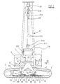
- Figure 1 is a side elevation of a tracked vehicle equipped with the invention, this latter shown in its utilization configuration.
- Figure 2 is the section II-II indicated in Figure 1.
- Figure 3 is a view similar to Figure 1, showing the invention in its non-utilization configuration, suitable for transportation of the tracked vehicle. Said figures show a robust frame 1, with the sides of which there are associated two carriages 2 for guiding respective crawler tracks 3.
- a thrust bearing device 4 On said frame 1 there is positioned a thrust bearing device 4, to the movable upper element of which there is fixed a platform 5 carrying an internal combustion engine unit 6, typically diesel, an operating cab 118, and all the hydraulic equipment for supplying pressurized oil to the control motors for the crawler tracks 3 and for the winches described hereinafter.
- the platform 5 is of rectangular plan, its longitudinal axis being parallel to the axis of the frame 1 when the machine is arranged for transportation (see Figure 3).
- the combination which has just been described is of usual type, i.e. consisting of a track-mounted frame with an overlying platform mounted on a thrust bearing of the type typically used for bucket or shovel excavators.
- the said frame 1 is associated with the apparatus of the invention to form a pipe laying machine, without any need to modify the frame 1.
- said lugs 50 and 51 can be provided by a plate associated with the apparatus of the invention by being suitably fixed to the platform 5, for example by bolts.
- the apparatus comprises a profiled structure 7 supporting a flat structure 8 which at its end carries a lifting hook 28.
- the structure 7 comprises a straight portion 70 lowerly hinged to the lug 50 on a horizontal axis 55 lying transversely to the platform 5, and a downwardly curved portion 71 extending beyond the lug 51 and the corresponding end of the platform 5, where it assumes the form of a fork 72 (see Figure 1).
- the arms of the fork 72 present respective terminal eyelets 66 the common axis of which is parallel to said horizontal axis 55.
- said fork 72 lies external to a track guide carriage 2, its eyelets 66 being removably coupled to the lower longitudinal edge of the respective track guide configuration 2.
- Each plate 10 presents a pair of robust holed lugs 9 for receiving the respective eyelet 66, and a locking catch 99 controlled by a hydraulic cylinder-piston unit 90.
- Said plates 10 and the relative accessories are preferably provided on both the track guide carriages 2.
- the arms of the fork 72 are provided externally with respective angle brackets 44, two eyelets 33 provided at the lower end of the flat structure 8 being permanently hinged to said arms and brackets 44 on a common horizontal axis 22 parallel to the axis of said eyelets 66.
- Said axis 22 constitutes the swing axis of said structure 8, which is of trapezium shape ( Figure 1) and is provided upperly with two swivel blocks 21 and 22 respectively.
- the metal cable 210 for adjusting the inclination of the structure 8 passes about the block 21.
- the cable 210 has one end fixed to the drum of a respective winch 211 and its opposite end fixed to the block 21 after passing about a fixed cable terminal block 212.
- the metal cable 200 for raising and lowering the hook 28 passes about the block 20, the cable 200 having one end fixed to the drum of a respective winch 201 and its opposite end fixed to the block 20 after passing about the movable cable terminal block 202 of the hook 28.
- Said fixed block 212 and said winches 211 and 201 are carried by the straight portion 70 of the profiled structure 7 ( Figure 2).
- the aforedescribed pipe laying machine combines the special characteristics of the two types of pipe laying machines described in the introduction, i.e. discharge of most of the weight carried by the hook 28 onto elements not forming part of the thrust bearing 4, and minimum vertical height because of the ability to lower the structure 8 along the longitudinal axis of the machine.
- the winch 211 is operated to lower the structure 8 until the overall assembly falls within the allowable vertical contour, and the hook 28 is immobilized for example as shown in Figure 3.
Landscapes
- Life Sciences & Earth Sciences (AREA)
- Agronomy & Crop Science (AREA)
- Engineering & Computer Science (AREA)
- Mechanical Engineering (AREA)
- Jib Cranes (AREA)
- Supports For Pipes And Cables (AREA)
- Component Parts Of Construction Machinery (AREA)
- Earth Drilling (AREA)
- Replacement Of Web Rolls (AREA)
- Bending Of Plates, Rods, And Pipes (AREA)
- Devices For Conveying Motion By Means Of Endless Flexible Members (AREA)
- Investigating Or Analyzing Materials By The Use Of Magnetic Means (AREA)
Claims (10)
- Appareil de transformation, par exemple en une machine de pose de tuyaux, d'un châssis motorisé (1) monté sur des voies à chenilles (3) et muni en partie supérieure d'une plate-forme horizontale rotative (5), caractérisé en ce qu'il comprend une première structure (7) qui, à une première extrémité, est destinée à être articulée sur la plate-forme autour d'un axe horizontal et, à l'autre extrémité, présente un dispositif d'accouplement destiné à être raccordé à un chariot (2) de guide de voie et sur lequel est articulée, sur un axe horizontal, une seconde structure (8) qui, à son extrémité libre, porte un organe de levage (28).
- Appareil selon la revendication 1, caractérisé en ce que la première structure (7) présente, à l'extrémité opposée à l'axe (55) sur lequel elle est articulée sur la plate-forme, une partie profilée (71) formant une concavité destinée à entourer la partie respective de plate-forme et la partie supérieure de la voie à chenille lorsque le système est dans sa configuration d'utilisation.
- Appareil selon la revendication 1, caractérisé en ce que le dispositif d'accouplement de la première structure (7) comporte au moins un élément terminal percé qui lui est fixé, et au moins un organe complémentaire percé (9) qui est fixé à l'extérieur de la base du chariot (2) de guide de voie et auquel est associé un organe d'accrochage de blocage (99).
- Appareil selon la revendication 3, caractérisé en ce que l'organe d'accrochage est commandé par un vérin hydraulique à cylindre et piston (90).
- Appareil selon la revendication 1, caractérisé en ce que, entre la plate-forme (5) et la première structure (7), est interposé un bras de longueur variable dont le rôle est de placer la première structure dans la position permettant son accouplement au chariot (2) de guidage de voie ou dans sa position de libération.
- Appareil selon la revendication 5, caractérisé en ce que le bras de longueur variable est un vérin hydraulique à cylindre et piston (12).
- Appareil selon les revendications 1 et 5, caractérisé en ce que les sièges dans lesquels sont articulés la première structure et le bras de longueur variable sur la plate-forme (5) du châssis sont constitués de patins (50) fixés rigidement à la plate-forme.
- Appareil selon les revendications 1 et 5, caractérisé en ce que les sièges dans lesquels la première structure (7) et le bras de longueur variable sont articulés sur la plate-forme (5) du châssis (1) sont formés par une plaque destinée à être fixée à la plate-forme.
- Appareil selon la revendication 1, caractérisé en ce que la seconde structure (8) peut pivoter par rapport à la première sous l'action d'une force de traction exercée par des câbles (210) commandés par un treuil supporté par la première structure (7).
- Appareil selon la revendication 1, caractérisé en ce que l'organe de levage, tel qu'un crochet (28), est déplacé sous l'action de la force de traction de câbles (210) commandés par un treuil respectif supporté par la première structure.
Applications Claiming Priority (3)
| Application Number | Priority Date | Filing Date | Title |
|---|---|---|---|
| ITRE20000124 | 2000-12-05 | ||
| IT2000RE000124A IT1319477B1 (it) | 2000-12-05 | 2000-12-05 | Attrezzatura atta a tipicamente trasformare un telaio montato sucingoli in una macchina posatubi. |
| PCT/EP2001/013747 WO2002046088A1 (fr) | 2000-12-05 | 2001-11-23 | Appareil permettant de transformer de façon caracteristique un chassis monte sur chenilles en une machine de pose de canalisations |
Publications (2)
| Publication Number | Publication Date |
|---|---|
| EP1339632A1 EP1339632A1 (fr) | 2003-09-03 |
| EP1339632B1 true EP1339632B1 (fr) | 2005-08-31 |
Family
ID=11453999
Family Applications (1)
| Application Number | Title | Priority Date | Filing Date |
|---|---|---|---|
| EP01999527A Expired - Lifetime EP1339632B1 (fr) | 2000-12-05 | 2001-11-23 | Appareil permettant de transformer de fa on caracteristique un chassis monte sur chenilles en une machine de pose de canalisations |
Country Status (9)
| Country | Link |
|---|---|
| US (1) | US6843619B2 (fr) |
| EP (1) | EP1339632B1 (fr) |
| AT (1) | ATE303339T1 (fr) |
| AU (1) | AU2368602A (fr) |
| CA (1) | CA2436841C (fr) |
| DE (1) | DE60113146T2 (fr) |
| ES (1) | ES2247203T3 (fr) |
| IT (1) | IT1319477B1 (fr) |
| WO (1) | WO2002046088A1 (fr) |
Families Citing this family (13)
| Publication number | Priority date | Publication date | Assignee | Title |
|---|---|---|---|---|
| AU2007201045B2 (en) * | 2002-03-08 | 2007-07-19 | Volvo Construction Equipment Ab | Pipelayer crane excavator apparatus and methods |
| US20070241074A9 (en) * | 2003-03-11 | 2007-10-18 | Davis Daniel E | Pipelayer crane excavator apparatus and methods |
| US20070267376A1 (en) * | 2003-03-11 | 2007-11-22 | Andre Faure | Pipe Layer Apparatus |
| GB0702161D0 (en) * | 2007-02-05 | 2007-03-14 | Technip France | Method and apparatus for laying a marine pipeline |
| USD567259S1 (en) | 2007-05-09 | 2008-04-22 | Davis Daniel E | Pipelayer |
| CN105035978A (zh) * | 2015-07-07 | 2015-11-11 | 王皓辉 | 一种吊管机吊臂主旋杆的结构及制作方法 |
| US10807839B2 (en) * | 2018-05-07 | 2020-10-20 | Caterpillar Inc. | Pipelayer machine having hoisting system with pivotable fairlead |
| US10773934B2 (en) * | 2018-05-21 | 2020-09-15 | Caterpillar Inc. | Machine having hoisting system with instrumented fairlead |
| US10994778B2 (en) | 2018-12-20 | 2021-05-04 | Rce Equipment Solutions, Inc. | Tracked vehicle with steering compensation |
| US11148915B2 (en) * | 2019-09-19 | 2021-10-19 | Caterpillar Inc. | Boom assembly and method of assembly thereof |
| US11970375B2 (en) * | 2021-10-04 | 2024-04-30 | Caterpillar Inc. | Pipelayer machine with forward towing winch configuration |
| US11970374B2 (en) * | 2021-10-04 | 2024-04-30 | Caterpillar Inc. | Pipelayer machine with rear engine configuration |
| US11802027B2 (en) * | 2022-03-25 | 2023-10-31 | Philbilt LLC | Hoist system |
Family Cites Families (18)
| Publication number | Priority date | Publication date | Assignee | Title |
|---|---|---|---|---|
| US1985285A (en) * | 1932-05-12 | 1934-12-25 | Highway Trailer Co | Side-mounted derrick for tractors |
| US2413529A (en) * | 1944-11-06 | 1946-12-31 | Laura B Swaney | Tractor crane |
| GB604316A (en) * | 1944-11-06 | 1948-07-01 | Robert Casper Swaney | Tractor crane |
| US2425663A (en) * | 1945-07-16 | 1947-08-12 | American Tractor Equip Corp | Hoist |
| US2712873A (en) * | 1949-11-22 | 1955-07-12 | Caterpillar Tractor Co | Pipe laying tractor |
| US3005559A (en) * | 1958-05-23 | 1961-10-24 | John Deere Plow Company | Side booms |
| US3598347A (en) * | 1969-10-07 | 1971-08-10 | Caterpillar Tractor Co | Apparatus for supporting and positioning pipe welders |
| US3785503A (en) * | 1972-05-30 | 1974-01-15 | Caterpillar Tractor Co | Boom control mechanism for tractors or the like |
| IT1004431B (it) * | 1974-03-28 | 1976-07-10 | Saipem Spa | Apparecchiatura perfezionata a ca valletto articolato per la posa in o il recupero da una trincea scava ta nel terreno di una tubazione |
| US4132317A (en) * | 1977-04-12 | 1979-01-02 | Spetsialnoe Konstruktorskoe Bjuro Gazstroimashina | Pipe laying crane |
| US4130204A (en) * | 1977-08-26 | 1978-12-19 | Pickard Kenneth L | Side boom pipe laying crane with pipe section alignment feature |
| US4682912A (en) * | 1979-07-10 | 1987-07-28 | Henry John T | Pipe laying apparatus |
| US4362435A (en) * | 1979-07-10 | 1982-12-07 | Henry John T | Apparatus for laying pipe |
| GB2104867B (en) * | 1981-05-08 | 1985-03-20 | Tonnes Force | Crane |
| US4666049A (en) * | 1985-12-20 | 1987-05-19 | Gilmore Transportation Services, Inc. | Sideboom excavator with lifting means |
| US4946051A (en) * | 1989-04-05 | 1990-08-07 | Cliff John O | Two-boom crawler crane |
| US6609622B2 (en) * | 2001-07-23 | 2003-08-26 | Raymond Forsyth | Bulldozer/pipelayer combination |
| US6494515B1 (en) * | 2002-01-02 | 2002-12-17 | Carl D. Kalbfleisch | Pole handler attachment |
-
2000
- 2000-12-05 IT IT2000RE000124A patent/IT1319477B1/it active
-
2001
- 2001-11-23 EP EP01999527A patent/EP1339632B1/fr not_active Expired - Lifetime
- 2001-11-23 CA CA2436841A patent/CA2436841C/fr not_active Expired - Fee Related
- 2001-11-23 AU AU2368602A patent/AU2368602A/xx not_active Withdrawn
- 2001-11-23 US US10/432,856 patent/US6843619B2/en not_active Expired - Lifetime
- 2001-11-23 DE DE60113146T patent/DE60113146T2/de not_active Expired - Lifetime
- 2001-11-23 WO PCT/EP2001/013747 patent/WO2002046088A1/fr not_active Ceased
- 2001-11-23 AT AT01999527T patent/ATE303339T1/de not_active IP Right Cessation
- 2001-11-23 ES ES01999527T patent/ES2247203T3/es not_active Expired - Lifetime
Also Published As
| Publication number | Publication date |
|---|---|
| IT1319477B1 (it) | 2003-10-10 |
| WO2002046088A1 (fr) | 2002-06-13 |
| ITRE20000124A0 (it) | 2000-12-05 |
| ATE303339T1 (de) | 2005-09-15 |
| ITRE20000124A1 (it) | 2002-06-05 |
| DE60113146T2 (de) | 2006-03-09 |
| ES2247203T3 (es) | 2006-03-01 |
| EP1339632A1 (fr) | 2003-09-03 |
| CA2436841C (fr) | 2010-01-26 |
| CA2436841A1 (fr) | 2002-06-13 |
| US20040033109A1 (en) | 2004-02-19 |
| US6843619B2 (en) | 2005-01-18 |
| AU2368602A (en) | 2002-06-18 |
| DE60113146D1 (de) | 2005-10-06 |
Similar Documents
| Publication | Publication Date | Title |
|---|---|---|
| US7845503B2 (en) | Pipe-laying machine | |
| EP1339632B1 (fr) | Appareil permettant de transformer de fa on caracteristique un chassis monte sur chenilles en une machine de pose de canalisations | |
| US7896178B2 (en) | Industrial vehicle counterweight system | |
| US8152412B2 (en) | Pipelayer with cab riser | |
| US20100180475A1 (en) | Heavy equipment vehicle for laying pipe | |
| CN102985351B (zh) | 举升框架设备 | |
| US5332110A (en) | Tractor mounted hydraulic pipelayer with side boom | |
| IE42743B1 (en) | Apparatus for handling pipes or pipelines | |
| KR102025327B1 (ko) | 붐 길이 조절되는 파이프 레이어 | |
| AU2002223686B2 (en) | Apparatus able typically to transform a frame mounted on crawler tracks into a pipe laying machine | |
| US2903803A (en) | Log handling apparatus | |
| EP4045452B1 (fr) | Grue mobile et procédé | |
| US7204378B2 (en) | Goods transshipment apparatus | |
| AU2002223686A1 (en) | Apparatus able typically to transform a frame mounted on crawler tracks into a pipe laying machine | |
| NL2024610B1 (en) | A mobile heavy lift crane system | |
| JP2577577Y2 (ja) | チュービング装置移動用台車 | |
| JP3029114U (ja) | 立坑用門形クレーン | |
| CN217076782U (zh) | 一种起吊运输设备 | |
| EP0152159A1 (fr) | Véhicules transportant des charges | |
| RU42013U1 (ru) | Эвакуатор неисправных транспортных средств | |
| CN218754698U (zh) | 自动装卸铁道装置 | |
| NL2009158B1 (nl) | Werkwijze voor het leggen van een pijpleiding en daarbij te gebruiken bergingstank. | |
| GB2158132A (en) | Pipe handling machine | |
| GB2158131A (en) | Pipe handling machine | |
| CN108298027A (zh) | 一种双轨小车拖曳式水下钻机翻转装置及工作方法 |
Legal Events
| Date | Code | Title | Description |
|---|---|---|---|
| PUAI | Public reference made under article 153(3) epc to a published international application that has entered the european phase |
Free format text: ORIGINAL CODE: 0009012 |
|
| 17P | Request for examination filed |
Effective date: 20030513 |
|
| AK | Designated contracting states |
Kind code of ref document: A1 Designated state(s): AT BE CH CY DE DK ES FI FR GB GR IE IT LI LU MC NL PT SE TR |
|
| AX | Request for extension of the european patent |
Extension state: AL LT LV MK RO SI |
|
| GRAP | Despatch of communication of intention to grant a patent |
Free format text: ORIGINAL CODE: EPIDOSNIGR1 |
|
| GRAS | Grant fee paid |
Free format text: ORIGINAL CODE: EPIDOSNIGR3 |
|
| GRAA | (expected) grant |
Free format text: ORIGINAL CODE: 0009210 |
|
| AK | Designated contracting states |
Kind code of ref document: B1 Designated state(s): AT BE CH CY DE DK ES FI FR GB GR IE IT LI LU MC NL PT SE TR |
|
| PG25 | Lapsed in a contracting state [announced via postgrant information from national office to epo] |
Ref country code: AT Free format text: LAPSE BECAUSE OF FAILURE TO SUBMIT A TRANSLATION OF THE DESCRIPTION OR TO PAY THE FEE WITHIN THE PRESCRIBED TIME-LIMIT Effective date: 20050831 Ref country code: NL Free format text: LAPSE BECAUSE OF FAILURE TO SUBMIT A TRANSLATION OF THE DESCRIPTION OR TO PAY THE FEE WITHIN THE PRESCRIBED TIME-LIMIT Effective date: 20050831 Ref country code: BE Free format text: LAPSE BECAUSE OF FAILURE TO SUBMIT A TRANSLATION OF THE DESCRIPTION OR TO PAY THE FEE WITHIN THE PRESCRIBED TIME-LIMIT Effective date: 20050831 Ref country code: CH Free format text: LAPSE BECAUSE OF FAILURE TO SUBMIT A TRANSLATION OF THE DESCRIPTION OR TO PAY THE FEE WITHIN THE PRESCRIBED TIME-LIMIT Effective date: 20050831 Ref country code: LI Free format text: LAPSE BECAUSE OF FAILURE TO SUBMIT A TRANSLATION OF THE DESCRIPTION OR TO PAY THE FEE WITHIN THE PRESCRIBED TIME-LIMIT Effective date: 20050831 Ref country code: FI Free format text: LAPSE BECAUSE OF FAILURE TO SUBMIT A TRANSLATION OF THE DESCRIPTION OR TO PAY THE FEE WITHIN THE PRESCRIBED TIME-LIMIT Effective date: 20050831 Ref country code: TR Free format text: LAPSE BECAUSE OF FAILURE TO SUBMIT A TRANSLATION OF THE DESCRIPTION OR TO PAY THE FEE WITHIN THE PRESCRIBED TIME-LIMIT Effective date: 20050831 |
|
| REG | Reference to a national code |
Ref country code: CH Ref legal event code: EP Ref country code: GB Ref legal event code: FG4D |
|
| REG | Reference to a national code |
Ref country code: IE Ref legal event code: FG4D |
|
| REF | Corresponds to: |
Ref document number: 60113146 Country of ref document: DE Date of ref document: 20051006 Kind code of ref document: P |
|
| PG25 | Lapsed in a contracting state [announced via postgrant information from national office to epo] |
Ref country code: IE Free format text: LAPSE BECAUSE OF NON-PAYMENT OF DUE FEES Effective date: 20051123 Ref country code: CY Free format text: LAPSE BECAUSE OF FAILURE TO SUBMIT A TRANSLATION OF THE DESCRIPTION OR TO PAY THE FEE WITHIN THE PRESCRIBED TIME-LIMIT Effective date: 20051123 |
|
| PG25 | Lapsed in a contracting state [announced via postgrant information from national office to epo] |
Ref country code: SE Free format text: LAPSE BECAUSE OF FAILURE TO SUBMIT A TRANSLATION OF THE DESCRIPTION OR TO PAY THE FEE WITHIN THE PRESCRIBED TIME-LIMIT Effective date: 20051130 Ref country code: GB Free format text: LAPSE BECAUSE OF NON-PAYMENT OF DUE FEES Effective date: 20051130 Ref country code: MC Free format text: LAPSE BECAUSE OF NON-PAYMENT OF DUE FEES Effective date: 20051130 Ref country code: GR Free format text: LAPSE BECAUSE OF FAILURE TO SUBMIT A TRANSLATION OF THE DESCRIPTION OR TO PAY THE FEE WITHIN THE PRESCRIBED TIME-LIMIT Effective date: 20051130 Ref country code: LU Free format text: LAPSE BECAUSE OF NON-PAYMENT OF DUE FEES Effective date: 20051130 Ref country code: DK Free format text: LAPSE BECAUSE OF FAILURE TO SUBMIT A TRANSLATION OF THE DESCRIPTION OR TO PAY THE FEE WITHIN THE PRESCRIBED TIME-LIMIT Effective date: 20051130 |
|
| PG25 | Lapsed in a contracting state [announced via postgrant information from national office to epo] |
Ref country code: PT Free format text: LAPSE BECAUSE OF FAILURE TO SUBMIT A TRANSLATION OF THE DESCRIPTION OR TO PAY THE FEE WITHIN THE PRESCRIBED TIME-LIMIT Effective date: 20060223 |
|
| NLV1 | Nl: lapsed or annulled due to failure to fulfill the requirements of art. 29p and 29m of the patents act | ||
| REG | Reference to a national code |
Ref country code: ES Ref legal event code: FG2A Ref document number: 2247203 Country of ref document: ES Kind code of ref document: T3 |
|
| REG | Reference to a national code |
Ref country code: CH Ref legal event code: PL |
|
| ET | Fr: translation filed | ||
| PLBE | No opposition filed within time limit |
Free format text: ORIGINAL CODE: 0009261 |
|
| STAA | Information on the status of an ep patent application or granted ep patent |
Free format text: STATUS: NO OPPOSITION FILED WITHIN TIME LIMIT |
|
| GBPC | Gb: european patent ceased through non-payment of renewal fee |
Effective date: 20051130 |
|
| 26N | No opposition filed |
Effective date: 20060601 |
|
| REG | Reference to a national code |
Ref country code: IE Ref legal event code: MM4A |
|
| REG | Reference to a national code |
Ref country code: FR Ref legal event code: PLFP Year of fee payment: 15 |
|
| REG | Reference to a national code |
Ref country code: FR Ref legal event code: PLFP Year of fee payment: 16 |
|
| PGFP | Annual fee paid to national office [announced via postgrant information from national office to epo] |
Ref country code: DE Payment date: 20161123 Year of fee payment: 16 Ref country code: FR Payment date: 20161123 Year of fee payment: 16 |
|
| PGFP | Annual fee paid to national office [announced via postgrant information from national office to epo] |
Ref country code: ES Payment date: 20161128 Year of fee payment: 16 Ref country code: IT Payment date: 20161128 Year of fee payment: 16 |
|
| REG | Reference to a national code |
Ref country code: DE Ref legal event code: R119 Ref document number: 60113146 Country of ref document: DE |
|
| REG | Reference to a national code |
Ref country code: FR Ref legal event code: ST Effective date: 20180731 |
|
| PG25 | Lapsed in a contracting state [announced via postgrant information from national office to epo] |
Ref country code: IT Free format text: LAPSE BECAUSE OF NON-PAYMENT OF DUE FEES Effective date: 20171123 Ref country code: FR Free format text: LAPSE BECAUSE OF NON-PAYMENT OF DUE FEES Effective date: 20171130 Ref country code: DE Free format text: LAPSE BECAUSE OF NON-PAYMENT OF DUE FEES Effective date: 20180602 |
|
| PG25 | Lapsed in a contracting state [announced via postgrant information from national office to epo] |
Ref country code: ES Free format text: LAPSE BECAUSE OF NON-PAYMENT OF DUE FEES Effective date: 20171124 |