EP1340031B1 - Vorrichtung zur bandsinterung im dauerbetrieb - Google Patents
Vorrichtung zur bandsinterung im dauerbetrieb Download PDFInfo
- Publication number
- EP1340031B1 EP1340031B1 EP01983626A EP01983626A EP1340031B1 EP 1340031 B1 EP1340031 B1 EP 1340031B1 EP 01983626 A EP01983626 A EP 01983626A EP 01983626 A EP01983626 A EP 01983626A EP 1340031 B1 EP1340031 B1 EP 1340031B1
- Authority
- EP
- European Patent Office
- Prior art keywords
- belt
- drawing drum
- belt conveyor
- sintering
- actuator
- Prior art date
- Legal status (The legal status is an assumption and is not a legal conclusion. Google has not performed a legal analysis and makes no representation as to the accuracy of the status listed.)
- Expired - Lifetime
Links
- 238000005245 sintering Methods 0.000 title claims abstract description 40
- 239000000463 material Substances 0.000 description 9
- 239000008188 pellet Substances 0.000 description 8
- 239000007789 gas Substances 0.000 description 3
- 229910001021 Ferroalloy Inorganic materials 0.000 description 2
- 230000005540 biological transmission Effects 0.000 description 2
- 238000004519 manufacturing process Methods 0.000 description 2
- 239000002184 metal Substances 0.000 description 2
- 229910001092 metal group alloy Inorganic materials 0.000 description 2
- 238000000034 method Methods 0.000 description 2
- 238000003723 Smelting Methods 0.000 description 1
- 239000007767 bonding agent Substances 0.000 description 1
- 239000012141 concentrate Substances 0.000 description 1
- 239000000109 continuous material Substances 0.000 description 1
- 238000001816 cooling Methods 0.000 description 1
- 238000002844 melting Methods 0.000 description 1
- 230000008018 melting Effects 0.000 description 1
- 238000005453 pelletization Methods 0.000 description 1
- 239000007779 soft material Substances 0.000 description 1
- 239000000126 substance Substances 0.000 description 1
- 230000009466 transformation Effects 0.000 description 1
- 238000000844 transformation Methods 0.000 description 1
Images

Classifications
-
- F—MECHANICAL ENGINEERING; LIGHTING; HEATING; WEAPONS; BLASTING
- F27—FURNACES; KILNS; OVENS; RETORTS
- F27B—FURNACES, KILNS, OVENS OR RETORTS IN GENERAL; OPEN SINTERING OR LIKE APPARATUS
- F27B21/00—Open or uncovered sintering apparatus; Other heat-treatment apparatus of like construction
- F27B21/06—Endless-strand sintering machines
-
- F—MECHANICAL ENGINEERING; LIGHTING; HEATING; WEAPONS; BLASTING
- F27—FURNACES; KILNS; OVENS; RETORTS
- F27D—DETAILS OR ACCESSORIES OF FURNACES, KILNS, OVENS OR RETORTS, IN SO FAR AS THEY ARE OF KINDS OCCURRING IN MORE THAN ONE KIND OF FURNACE
- F27D21/00—Arrangement of monitoring devices; Arrangement of safety devices
- F27D2021/0057—Security or safety devices, e.g. for protection against heat, noise, pollution or too much duress; Ergonomic aspects
Definitions
- the present invention relates to a device for moving the belt of a belt conveyor used in continuously operated belt sintering and for aligning the sintering belt conveyed on the belt conveyor with respect to the sintering device.
- the material to be sintered is heated up to a high temperature, where the originally soft material that is difficult to treat is, by means of chemical forces, transformed to an essentially hard material that is easier to treat.
- the finely divided dried concentrate to be processed is first transformed, in the presence of a bonding agent and for instance in a pelletizing drum, into essentially soft, spherical pellets.
- the essentially soft, spherical pellets are nowadays usually sintered by means of belt sintering.
- the essentially soft pellets are distributed as an essentially continuous material bed. Said material bed is, while the conveyor belt moves, first subjected to a preheating step, then to a sintering step proper, and further to a cooling step, whereafter the material bed composed of essentially soft pellets has turned into a bed of essentially hard pellets to be fed into a smelting furnace.
- a drawback with current conveyor belts meant for belt sintering is a jerky motion of the conveyor belt, which jerky motion is caused by dead strokes between the long axis and the multiple-stage gear while rotating a large-size drawing drum at a low speed from the drawing drum axis.
- a jerky motion in the conveyor belt in turn results in a wobbly motion of the structures of the sintering furnace, which is a strain particularly to the sintering furnace linings and thus shortens the working life of the equipment and reduces the operational security of said equipment.
- the object of the present invention is to eliminate some bf the drawbacks of the prior art and to realize an improved device that is more secure in operation, for moving a belt conveyor used in a continuously operated belt sintering furnace and for aligning the belt of the conveyor so that the working age of the belt conveyor and the belt can be extended.
- the device according to the invention is meant to be used in a belt conveyor that is employed for sintering a material bed, created on the belt of a belt conveyor, of pellets made of a finely divided, metal bearing or metal alloy bearing material in a continuously operated sintering furnace, where through the belt of the belt conveyor there are conducted hot gases in order to sinter the material bed while the material bed moves through the various sintering steps along the conveyor belt.
- the actuator device of the belt conveyor connected to the drawing drum of the belt conveyor and installed in the immediate vicinity of the other end of the drawing drum, is arranged, with respect to the belt conveyor, so that the aligning of the belt of the conveyor can, when necessary, be carried out in an essentially easy and simple way, essentially by moving the whole actuator device at the same time.
- the actuator device of a belt conveyor meant for sintering pellets made of some metal bearing or metal alloy bearing material includes at least one rotary element, i.e. cogged wheel, that is co-centric with the drawing drum of the belt conveyor and has a diameter that is essentially equal to the diameter of the drawing drum, said cogged wheel being advantageously attached to the drawing drum of the belt conveyor, advantageously at that end of the drum, in the vicinity whereof the whole actuator device of the belt conveyor is installed.
- the cogged wheel can also be installed so that the cogged wheel is arranged on the same axis with the drawing drum of the belt conveyor, but is separate from the drawing drum of the belt conveyor.
- the cogged wheel is installed to be in contact with at least one actuator element, actuator wheel, the diameter whereof is essentially smaller than that of the cogged wheel, so that the cogged wheel and the actuator wheel together form a gear wheel drive that is rotated by means of an actuator motor connected to the actuator wheel.
- the number of cogged wheels in the device according to the invention is the same as the number of actuator wheels.
- a cogged wheel can be rotated around its axis at a desired speed by means of an actuator wheel with an essentially smaller diameter. Owing to the essentially small actuator wheel, the transmission ratio in the actuator device can be reduced, in which case the dead strokes caused by the transmission gear remain slight. Thus also the jerky motion of the belt conveyor can be essentially reduced.
- At least the support of that end of the axis of the drawing drum of the belt conveyor that is located nearest to the actuator device and the actuator device of the drawing drum are according to the invention installed on one and the same foundation, so that when aligning the belt by moving the drawing drum, the whole actuator device is moved along. Consequently the moving of the cogged gears, i.e. the cogged wheel and the actuator wheel contained in the actuator device, with respect to each other need not be carried out while adjusting the position of the drawing drum when aligning the belt of the belt conveyor.
- the aligning of the belt used for sintering is carried out when necessary, in case transformations caused by heat or by some other factor have taken place in the belt.
- an actuator motor rotates the actuator wheel, which is, by intermediation of the cogging provided on its outer circumference, in contact with the cogged wheel with an essentially larger diameter that is connected co-centrically to the drawing drum.
- the actuator wheel further rotates the cogged wheel by using the cogging provided on the outer circumference of the cogged wheel.
- the cogged wheel with the large diameter is made to rotate, by the actuator wheel with the small diameter, at an essentially slow speed and consequently also in a smooth fashion.
- the cogged wheel further rotates a drawing drum that is installed co-centrically on the same axis, so that the conveyor belt placed on the drawing drum circumference and used for sintering is also made to move at an advantageously slow and an essentially even speed, with respect to the requirements of the sintering process.
- Figure 1 illustrates a preferred embodiment of the invention, seen from the side
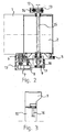
- Figure 2 is a top-view illustration of an embodiment according to figure 1, located in the immediate vicinity of the drawing drum of the belt conveyor
- Figure 3 illustrates the embodiment according to figure 1, seen in the direction A-A.
- the belt 1 of the belt conveyor is movably installed around the drawing drum 2 and the folding drum 3, so that the moving belt 1 passes through the sintering device 4.
- a cogged wheel 5 that has a larger diameter than the drawing drum 2 and is provided with cogging on the outer circumference.
- the cogged wheel 5 is rotated by means of an actuator wheel 6 that is in mechanical contact with the cogging of the cogged wheel 5 and is likewise provided with a cogging on the outer circumference, but has an essentially smaller diameter than the cogged wheel 5.
- the actuator wheel 6 is, by intermediation of the axis thereof, connected further, by means of a gear drive 7, to the actuating motor 8, which rotates the actuator wheel 6.
- the actuator wheel 6 and the actuating motor 8 are supported against the same foundation 9 that is installed movably with respect to the support structures 10 of the belt conveyor.
- the foundation 9 also includes means 17 for permanently fixing the foundation 9 with respect to the support structures. 10.
- the supporting element 12 of that end of the axis of the drawing drum 2 that is opposite to the actuator element is arranged on a separate foundation 13.
- the supporting element 12 is provided with at least one moving element 14, whereby the position of the axis of the drawing drum 2 can be adjusted, when the drawing drum 2 is realigned.
- the foundation 9, against which there are supported both the actuator wheel 6 of the drawing drum, the actuating motor 8 and that end of the axis 15 of the drawing drum 2 that falls on the side of the actuator device are moved to the desired position, advantageously around the support element 16 of the foundation 9.
- the moving element 14 attached to the support element 12 of that end of the axis of the drawing drum that is opposite to the actuator device the axis of the drawing drum 2 is shifted to the desired position also at the other end.
Landscapes
- Engineering & Computer Science (AREA)
- Mechanical Engineering (AREA)
- General Engineering & Computer Science (AREA)
- Structure Of Belt Conveyors (AREA)
- Tunnel Furnaces (AREA)
- Powder Metallurgy (AREA)
- Belt Conveyors (AREA)
- Manufacture And Refinement Of Metals (AREA)
- Management Or Editing Of Information On Record Carriers (AREA)
- Sewing Machines And Sewing (AREA)
Claims (5)
- Vorrichtung zum Bewegen des Bandes einer Band-Förderanlage in Verwendung zum kontinuierlich betriebenen Bandsintern zwischen der Zugtrommel und der Falttrommel, und zum Ausrichten des Bandsinter-Bandes, das durch die Band-Förderanlage mit Bezug auf die Sintervornchtung zu bewegen ist,
dadurch gekennzeichnet, dass zum Rotieren der Zugtrommel (2) der zum Bandsintern verwendeten Band-Förderanlage eine Antriebsvorrichtung (5, 6, 8) der Band-Förderanlage in der unmittelbaren Nähe des anderen Endes der Zugtrommel installiert ist, wobei mindestens ein Rotationselement (5), das kozentrisch mit der Achse (15) der Zugtrommel installiert und am Außenumfang verzahnt ist, an mindestens einem Antriebselement (6) angeschlossen ist, das im Durchmesser wesentlich kleiner ist und am Außenumfang verzahnt ist, welches Antriebselement (6) mit Hilfe eines Antriebsmotors (8) in Rotation versetzt werden kann, der zur Antriebsvorrichtung gehört, und dass zum Ausrichten des Bandes (1) der Band-Förderanlage bezüglich der Sintervorrichtung (4) die Antriebsvorrichtung der Band-Förderanlage mit Bezug auf die Band-Förderanlage installiert ist, so dass das Ausrichten des Bandes (1) der Band-Förderanlage bei Bedarf ausgeführt werden kann, indem im Wesentlichen die gesamte Antriebsvorrichtung (5, 6, 8) der Band-Förderanlage bewegt wird, und dass zumindest die Unterstützung (11) desjenigen Endes der Achse (15) der Zugtrommel, das am nächsten zur Antriebsvorrichtung (5, 6, 8) und der Antriebsvorrichtung (5, 6, 8) der Zugtrommel ist, auf demselben Basisfundament installiert ist. - Vorrichtung nach Anspruch 1,
dadurch gekennzeichnet, dass das gezahnte Rotationselement (5) zum Drehen der Zugtrommel (2) an dem Ende der Zugtrommel (2) befestigt ist. - Vorrichtung nach Anspruch 1,
dadurch gekennzeichnet, dass das gezahnte Rotationselement zum Drehen der Zugtrommel (2) auf der Achse (15) der Zugtrommel installiert ist. - Vorrichtung nach einem der vorangehenden Ansprüche,
dadurch gekennzeichnet, dass der Durchmesser des Rotationselements (5) im Wesentlichen dem Durchmesser der Zugtrommel (2) entspricht. - Vorrichtung nach einem der vorangehenden Ansprüche,
dadurch gekennzeichnet, dass das Trägerelement (12) desjenigen Endes der Achse der Zugtrommel (2), das gegenüber der Antriebsvorrichtung (5, 6, 8) ist, mit einem Element (14) zum Bewegen der Zugtrommel-Achse versehen ist.
Applications Claiming Priority (3)
| Application Number | Priority Date | Filing Date | Title |
|---|---|---|---|
| FI20002524A FI113038B (fi) | 2000-11-17 | 2000-11-17 | Laitteisto jatkuvatoimiseen nauhasintraukseen |
| FI20002524 | 2000-11-17 | ||
| PCT/FI2001/000994 WO2002040933A1 (en) | 2000-11-17 | 2001-11-16 | Device for continuously operated belt sintering |
Publications (2)
| Publication Number | Publication Date |
|---|---|
| EP1340031A1 EP1340031A1 (de) | 2003-09-03 |
| EP1340031B1 true EP1340031B1 (de) | 2006-12-13 |
Family
ID=8559518
Family Applications (1)
| Application Number | Title | Priority Date | Filing Date |
|---|---|---|---|
| EP01983626A Expired - Lifetime EP1340031B1 (de) | 2000-11-17 | 2001-11-16 | Vorrichtung zur bandsinterung im dauerbetrieb |
Country Status (13)
| Country | Link |
|---|---|
| US (1) | US6805235B2 (de) |
| EP (1) | EP1340031B1 (de) |
| CN (1) | CN100358786C (de) |
| AT (1) | ATE348306T1 (de) |
| AU (1) | AU2002215071A1 (de) |
| BR (1) | BR0115399B1 (de) |
| CA (1) | CA2427399A1 (de) |
| DE (1) | DE60125229T2 (de) |
| EA (1) | EA004726B1 (de) |
| FI (1) | FI113038B (de) |
| NO (1) | NO20031968L (de) |
| WO (1) | WO2002040933A1 (de) |
| ZA (1) | ZA200303333B (de) |
Families Citing this family (2)
| Publication number | Priority date | Publication date | Assignee | Title |
|---|---|---|---|---|
| JP5040465B2 (ja) * | 2006-08-18 | 2012-10-03 | コニカミノルタホールディングス株式会社 | ベルト搬送装置における蛇行制御手段の調整方法 |
| CN105129762B (zh) * | 2015-09-22 | 2017-04-19 | 南京工程学院 | 一种连续生产磷酸铁锂正极材料的带式气氛烧结炉 |
Family Cites Families (10)
| Publication number | Priority date | Publication date | Assignee | Title |
|---|---|---|---|---|
| US3193086A (en) * | 1961-06-27 | 1965-07-06 | Rohm & Haas | Belt training in conveyor systems |
| US3159268A (en) * | 1961-11-02 | 1964-12-01 | Rohm & Haas | Training control for conveyor belts |
| US3362686A (en) * | 1966-05-11 | 1968-01-09 | Lincoln Mfg Co | Drive for rotating drum |
| GB2157249B (en) * | 1984-03-08 | 1987-08-19 | Karl Hehl | A conveyor means |
| DE3439456A1 (de) * | 1984-10-27 | 1986-07-17 | ELTI Apparatebau und Elektronik GmbH, 6106 Erzhausen | Steuervorrichtung zum ausrichten eines um zwei rollen umlaufenden endlosbandes |
| DE3724126C2 (de) * | 1987-07-21 | 1995-04-13 | Telair Int Cargo Sys Gmbh | Antriebsrolleneinheit |
| CN2246138Y (zh) * | 1996-01-15 | 1997-01-29 | 孙付江 | 齿条式输送带纠偏机 |
| CN2249741Y (zh) * | 1996-01-23 | 1997-03-19 | 武进市华东输送带设备厂 | 输送皮带齿式自动纠偏传动装置 |
| WO1999000317A1 (en) * | 1997-06-19 | 1999-01-07 | Bryant Products, Inc. | Infinitely variable speed motorized conveyor pulley using a brushless dc motor |
| DE19811130A1 (de) * | 1998-03-16 | 1999-09-23 | Hese Gmbh Maschf Ernst | Trommelmotor mit Getriebe |
-
2000
- 2000-11-17 FI FI20002524A patent/FI113038B/fi not_active IP Right Cessation
-
2001
- 2001-11-16 EA EA200300576A patent/EA004726B1/ru not_active IP Right Cessation
- 2001-11-16 EP EP01983626A patent/EP1340031B1/de not_active Expired - Lifetime
- 2001-11-16 CN CNB018190340A patent/CN100358786C/zh not_active Expired - Lifetime
- 2001-11-16 WO PCT/FI2001/000994 patent/WO2002040933A1/en not_active Ceased
- 2001-11-16 AT AT01983626T patent/ATE348306T1/de active
- 2001-11-16 AU AU2002215071A patent/AU2002215071A1/en not_active Abandoned
- 2001-11-16 BR BRPI0115399-4A patent/BR0115399B1/pt not_active IP Right Cessation
- 2001-11-16 DE DE60125229T patent/DE60125229T2/de not_active Expired - Lifetime
- 2001-11-16 CA CA002427399A patent/CA2427399A1/en not_active Abandoned
- 2001-11-16 US US10/432,055 patent/US6805235B2/en not_active Expired - Fee Related
-
2003
- 2003-04-30 ZA ZA200303333A patent/ZA200303333B/en unknown
- 2003-04-30 NO NO20031968A patent/NO20031968L/no unknown
Also Published As
| Publication number | Publication date |
|---|---|
| US6805235B2 (en) | 2004-10-19 |
| ATE348306T1 (de) | 2007-01-15 |
| EP1340031A1 (de) | 2003-09-03 |
| CN1474926A (zh) | 2004-02-11 |
| FI20002524L (fi) | 2002-05-18 |
| BR0115399A (pt) | 2004-07-06 |
| FI113038B (fi) | 2004-02-27 |
| EA004726B1 (ru) | 2004-08-26 |
| AU2002215071A1 (en) | 2002-05-27 |
| FI20002524A0 (fi) | 2000-11-17 |
| DE60125229T2 (de) | 2007-04-05 |
| US20040074740A1 (en) | 2004-04-22 |
| NO20031968D0 (no) | 2003-04-30 |
| WO2002040933A1 (en) | 2002-05-23 |
| CN100358786C (zh) | 2008-01-02 |
| ZA200303333B (en) | 2003-10-31 |
| CA2427399A1 (en) | 2002-05-23 |
| DE60125229D1 (de) | 2007-01-25 |
| BR0115399B1 (pt) | 2009-08-11 |
| EA200300576A1 (ru) | 2003-10-30 |
| NO20031968L (no) | 2003-04-30 |
Similar Documents
| Publication | Publication Date | Title |
|---|---|---|
| CN103648931B (zh) | 具有可转动的换位部段的输送设备 | |
| KR101705371B1 (ko) | 로터리 킬른 및 제조물 | |
| JP5592624B2 (ja) | ロータリーキルン | |
| KR19990045506A (ko) | 압연기에서 빌레트를 처리하기 위한 장치 및 방법 | |
| EP1340031B1 (de) | Vorrichtung zur bandsinterung im dauerbetrieb | |
| CN202913027U (zh) | 双速炉辊及连续式辊棒热处理炉 | |
| EP3119161A1 (de) | Wärmebehandlungsvorrichtung und wärmebehandlungsverfahren | |
| JP2006057939A (ja) | ロータリーキルンの支持装置 | |
| CN110343833B (zh) | 一种基于金属零部件加工用连续式网带加热炉 | |
| US8161786B2 (en) | Apparatus for feeding and turning tube products into a pilger mill machine | |
| KR101620583B1 (ko) | 핫스탬핑용 고주파 가열시스템 | |
| US4670884A (en) | Rotating carbon or graphite electrode column to be used both in open- and submerged-arc furnaces | |
| CN208840480U (zh) | 一种双金属冶金结合复合无缝管管坯生产装置 | |
| WO2018019920A1 (en) | Conveying through furnaces | |
| JP2013216959A (ja) | リング状部材の熱処理設備 | |
| JP2009014328A (ja) | ロータリーキルン | |
| JPH074470Y2 (ja) | 搬送装置 | |
| CN108971453A (zh) | 一种双金属冶金结合复合无缝管管坯生产装置 | |
| KR100516500B1 (ko) | 용광로의 장입슈트 구동장치 | |
| JP2007169670A (ja) | リング状品の焼入用誘導加熱装置 | |
| CN118816539B (zh) | 热弯一体岩板台盆烧制用窑车 | |
| KR100591049B1 (ko) | 연속적으로 작동되는 열처리 노내의 피처리 재료를지지하기 위한 장치 | |
| JP2007146261A (ja) | リング状品の焼入用誘導加熱装置およびリング状品組込機械部品の連続生産ライン | |
| JPS6138387A (ja) | ロ−タリ−キルン | |
| KR101443796B1 (ko) | 연속주조 주편의 표면처리장치 및 이를 이용한 연속주조 주편의 표면처리방법 |
Legal Events
| Date | Code | Title | Description |
|---|---|---|---|
| PUAI | Public reference made under article 153(3) epc to a published international application that has entered the european phase |
Free format text: ORIGINAL CODE: 0009012 |
|
| 17P | Request for examination filed |
Effective date: 20030530 |
|
| AK | Designated contracting states |
Kind code of ref document: A1 Designated state(s): AT BE CH CY DE DK ES FI FR GB GR IE IT LI LU MC NL PT SE TR |
|
| AX | Request for extension of the european patent |
Extension state: AL LT LV MK RO SI |
|
| GRAP | Despatch of communication of intention to grant a patent |
Free format text: ORIGINAL CODE: EPIDOSNIGR1 |
|
| RIC1 | Information provided on ipc code assigned before grant |
Ipc: F27B 21/06 20060101AFI20060515BHEP Ipc: B65G 23/08 20060101ALI20060515BHEP |
|
| GRAS | Grant fee paid |
Free format text: ORIGINAL CODE: EPIDOSNIGR3 |
|
| RAP1 | Party data changed (applicant data changed or rights of an application transferred) |
Owner name: OUTOKUMPU TECHNOLOGY OY |
|
| GRAA | (expected) grant |
Free format text: ORIGINAL CODE: 0009210 |
|
| RAP1 | Party data changed (applicant data changed or rights of an application transferred) |
Owner name: OUTOKUMPU TECHNOLOGY OYJ |
|
| AK | Designated contracting states |
Kind code of ref document: B1 Designated state(s): AT BE CH CY DE DK ES FI FR GB GR IE IT LI LU MC NL PT SE TR |
|
| AX | Request for extension of the european patent |
Extension state: AL |
|
| PG25 | Lapsed in a contracting state [announced via postgrant information from national office to epo] |
Ref country code: CH Free format text: LAPSE BECAUSE OF FAILURE TO SUBMIT A TRANSLATION OF THE DESCRIPTION OR TO PAY THE FEE WITHIN THE PRESCRIBED TIME-LIMIT Effective date: 20061213 Ref country code: FI Free format text: LAPSE BECAUSE OF FAILURE TO SUBMIT A TRANSLATION OF THE DESCRIPTION OR TO PAY THE FEE WITHIN THE PRESCRIBED TIME-LIMIT Effective date: 20061213 Ref country code: LI Free format text: LAPSE BECAUSE OF FAILURE TO SUBMIT A TRANSLATION OF THE DESCRIPTION OR TO PAY THE FEE WITHIN THE PRESCRIBED TIME-LIMIT Effective date: 20061213 Ref country code: BE Free format text: LAPSE BECAUSE OF FAILURE TO SUBMIT A TRANSLATION OF THE DESCRIPTION OR TO PAY THE FEE WITHIN THE PRESCRIBED TIME-LIMIT Effective date: 20061213 Ref country code: NL Free format text: LAPSE BECAUSE OF FAILURE TO SUBMIT A TRANSLATION OF THE DESCRIPTION OR TO PAY THE FEE WITHIN THE PRESCRIBED TIME-LIMIT Effective date: 20061213 Ref country code: DK Free format text: LAPSE BECAUSE OF FAILURE TO SUBMIT A TRANSLATION OF THE DESCRIPTION OR TO PAY THE FEE WITHIN THE PRESCRIBED TIME-LIMIT Effective date: 20061213 Ref country code: IT Free format text: LAPSE BECAUSE OF FAILURE TO SUBMIT A TRANSLATION OF THE DESCRIPTION OR TO PAY THE FEE WITHIN THE PRESCRIBED TIME-LIMIT;WARNING: LAPSES OF ITALIAN PATENTS WITH EFFECTIVE DATE BEFORE 2007 MAY HAVE OCCURRED AT ANY TIME BEFORE 2007. THE CORRECT EFFECTIVE DATE MAY BE DIFFERENT FROM THE ONE RECORDED. Effective date: 20061213 |
|
| REG | Reference to a national code |
Ref country code: GB Ref legal event code: FG4D |
|
| REG | Reference to a national code |
Ref country code: CH Ref legal event code: EP |
|
| REG | Reference to a national code |
Ref country code: IE Ref legal event code: FG4D |
|
| REF | Corresponds to: |
Ref document number: 60125229 Country of ref document: DE Date of ref document: 20070125 Kind code of ref document: P |
|
| PG25 | Lapsed in a contracting state [announced via postgrant information from national office to epo] |
Ref country code: ES Free format text: LAPSE BECAUSE OF FAILURE TO SUBMIT A TRANSLATION OF THE DESCRIPTION OR TO PAY THE FEE WITHIN THE PRESCRIBED TIME-LIMIT Effective date: 20070324 |
|
| REG | Reference to a national code |
Ref country code: SE Ref legal event code: TRGR |
|
| PG25 | Lapsed in a contracting state [announced via postgrant information from national office to epo] |
Ref country code: PT Free format text: LAPSE BECAUSE OF FAILURE TO SUBMIT A TRANSLATION OF THE DESCRIPTION OR TO PAY THE FEE WITHIN THE PRESCRIBED TIME-LIMIT Effective date: 20070514 |
|
| NLV1 | Nl: lapsed or annulled due to failure to fulfill the requirements of art. 29p and 29m of the patents act | ||
| REG | Reference to a national code |
Ref country code: CH Ref legal event code: PL |
|
| EN | Fr: translation not filed | ||
| RAP2 | Party data changed (patent owner data changed or rights of a patent transferred) |
Owner name: OUTOTEC OYJ |
|
| PLBE | No opposition filed within time limit |
Free format text: ORIGINAL CODE: 0009261 |
|
| STAA | Information on the status of an ep patent application or granted ep patent |
Free format text: STATUS: NO OPPOSITION FILED WITHIN TIME LIMIT |
|
| 26N | No opposition filed |
Effective date: 20070914 |
|
| PG25 | Lapsed in a contracting state [announced via postgrant information from national office to epo] |
Ref country code: FR Free format text: LAPSE BECAUSE OF FAILURE TO SUBMIT A TRANSLATION OF THE DESCRIPTION OR TO PAY THE FEE WITHIN THE PRESCRIBED TIME-LIMIT Effective date: 20070803 Ref country code: GR Free format text: LAPSE BECAUSE OF FAILURE TO SUBMIT A TRANSLATION OF THE DESCRIPTION OR TO PAY THE FEE WITHIN THE PRESCRIBED TIME-LIMIT Effective date: 20070314 |
|
| PG25 | Lapsed in a contracting state [announced via postgrant information from national office to epo] |
Ref country code: MC Free format text: LAPSE BECAUSE OF NON-PAYMENT OF DUE FEES Effective date: 20071130 |
|
| PG25 | Lapsed in a contracting state [announced via postgrant information from national office to epo] |
Ref country code: IE Free format text: LAPSE BECAUSE OF NON-PAYMENT OF DUE FEES Effective date: 20071116 |
|
| PG25 | Lapsed in a contracting state [announced via postgrant information from national office to epo] |
Ref country code: FR Free format text: LAPSE BECAUSE OF FAILURE TO SUBMIT A TRANSLATION OF THE DESCRIPTION OR TO PAY THE FEE WITHIN THE PRESCRIBED TIME-LIMIT Effective date: 20061213 |
|
| PG25 | Lapsed in a contracting state [announced via postgrant information from national office to epo] |
Ref country code: LU Free format text: LAPSE BECAUSE OF NON-PAYMENT OF DUE FEES Effective date: 20071116 Ref country code: CY Free format text: LAPSE BECAUSE OF FAILURE TO SUBMIT A TRANSLATION OF THE DESCRIPTION OR TO PAY THE FEE WITHIN THE PRESCRIBED TIME-LIMIT Effective date: 20061213 |
|
| PG25 | Lapsed in a contracting state [announced via postgrant information from national office to epo] |
Ref country code: TR Free format text: LAPSE BECAUSE OF FAILURE TO SUBMIT A TRANSLATION OF THE DESCRIPTION OR TO PAY THE FEE WITHIN THE PRESCRIBED TIME-LIMIT Effective date: 20061213 |
|
| REG | Reference to a national code |
Ref country code: DE Ref legal event code: R082 Ref document number: 60125229 Country of ref document: DE Representative=s name: K & H BONAPAT, DE |
|
| REG | Reference to a national code |
Ref country code: DE Ref legal event code: R082 Ref document number: 60125229 Country of ref document: DE Representative=s name: K & H BONAPAT PATENTANWAELTE KOCH - VON BEHREN, DE Effective date: 20130927 Ref country code: DE Ref legal event code: R081 Ref document number: 60125229 Country of ref document: DE Owner name: OUTOTEC OYJ, FI Free format text: FORMER OWNER: OUTOKUMPU TECHNOLOGY OYJ, ESPOO, FI Effective date: 20130927 Ref country code: DE Ref legal event code: R082 Ref document number: 60125229 Country of ref document: DE Representative=s name: K & H BONAPAT, DE Effective date: 20130927 |
|
| PGFP | Annual fee paid to national office [announced via postgrant information from national office to epo] |
Ref country code: IT Payment date: 20131128 Year of fee payment: 13 |
|
| PG25 | Lapsed in a contracting state [announced via postgrant information from national office to epo] |
Ref country code: IT Free format text: LAPSE BECAUSE OF NON-PAYMENT OF DUE FEES Effective date: 20141116 |
|
| PGFP | Annual fee paid to national office [announced via postgrant information from national office to epo] |
Ref country code: GB Payment date: 20151118 Year of fee payment: 15 |
|
| PGFP | Annual fee paid to national office [announced via postgrant information from national office to epo] |
Ref country code: SE Payment date: 20151118 Year of fee payment: 15 |
|
| REG | Reference to a national code |
Ref country code: SE Ref legal event code: EUG |
|
| GBPC | Gb: european patent ceased through non-payment of renewal fee |
Effective date: 20161116 |
|
| PG25 | Lapsed in a contracting state [announced via postgrant information from national office to epo] |
Ref country code: SE Free format text: LAPSE BECAUSE OF NON-PAYMENT OF DUE FEES Effective date: 20161117 |
|
| PG25 | Lapsed in a contracting state [announced via postgrant information from national office to epo] |
Ref country code: GB Free format text: LAPSE BECAUSE OF NON-PAYMENT OF DUE FEES Effective date: 20161116 |
|
| PGFP | Annual fee paid to national office [announced via postgrant information from national office to epo] |
Ref country code: AT Payment date: 20201119 Year of fee payment: 20 Ref country code: DE Payment date: 20201119 Year of fee payment: 20 |
|
| REG | Reference to a national code |
Ref country code: DE Ref legal event code: R071 Ref document number: 60125229 Country of ref document: DE |
|
| REG | Reference to a national code |
Ref country code: AT Ref legal event code: MK07 Ref document number: 348306 Country of ref document: AT Kind code of ref document: T Effective date: 20211116 |