EP1340552A2 - Dispositif d'application de produit fluide - Google Patents
Dispositif d'application de produit fluide Download PDFInfo
- Publication number
- EP1340552A2 EP1340552A2 EP02012003A EP02012003A EP1340552A2 EP 1340552 A2 EP1340552 A2 EP 1340552A2 EP 02012003 A EP02012003 A EP 02012003A EP 02012003 A EP02012003 A EP 02012003A EP 1340552 A2 EP1340552 A2 EP 1340552A2
- Authority
- EP
- European Patent Office
- Prior art keywords
- nozzle outlet
- outlet opening
- product
- support
- support device
- Prior art date
- Legal status (The legal status is an assumption and is not a legal conclusion. Google has not performed a legal analysis and makes no representation as to the accuracy of the status listed.)
- Withdrawn
Links
- 239000000463 material Substances 0.000 title description 6
- 239000012530 fluid Substances 0.000 title 1
- 239000000853 adhesive Substances 0.000 claims abstract description 12
- 230000001070 adhesive effect Effects 0.000 claims abstract description 12
- 239000003973 paint Substances 0.000 claims abstract description 6
- 238000000576 coating method Methods 0.000 claims description 8
- 239000011248 coating agent Substances 0.000 claims description 7
- 230000009969 flowable effect Effects 0.000 claims description 6
- 239000000126 substance Substances 0.000 claims description 4
- 239000002966 varnish Substances 0.000 claims description 4
- 239000004922 lacquer Substances 0.000 abstract 2
- 239000003292 glue Substances 0.000 description 4
- 238000011109 contamination Methods 0.000 description 2
- 239000007788 liquid Substances 0.000 description 2
- 238000004519 manufacturing process Methods 0.000 description 2
- 238000000034 method Methods 0.000 description 2
- 230000007704 transition Effects 0.000 description 2
- 239000004820 Pressure-sensitive adhesive Substances 0.000 description 1
- 238000004026 adhesive bonding Methods 0.000 description 1
- 239000011111 cardboard Substances 0.000 description 1
- 239000003795 chemical substances by application Substances 0.000 description 1
- 238000005520 cutting process Methods 0.000 description 1
- 230000007246 mechanism Effects 0.000 description 1
- 239000002184 metal Substances 0.000 description 1
- 229910052751 metal Inorganic materials 0.000 description 1
- 150000002739 metals Chemical class 0.000 description 1
- 239000000123 paper Substances 0.000 description 1
- 239000011087 paperboard Substances 0.000 description 1
- 239000004033 plastic Substances 0.000 description 1
- 229920003023 plastic Polymers 0.000 description 1
- 239000000758 substrate Substances 0.000 description 1
- 230000001960 triggered effect Effects 0.000 description 1
- 239000002023 wood Substances 0.000 description 1
Images

Classifications
-
- B—PERFORMING OPERATIONS; TRANSPORTING
- B05—SPRAYING OR ATOMISING IN GENERAL; APPLYING FLUENT MATERIALS TO SURFACES, IN GENERAL
- B05C—APPARATUS FOR APPLYING FLUENT MATERIALS TO SURFACES, IN GENERAL
- B05C5/00—Apparatus in which liquid or other fluent material is projected, poured or allowed to flow on to the surface of the work
- B05C5/02—Apparatus in which liquid or other fluent material is projected, poured or allowed to flow on to the surface of the work the liquid or other fluent material being discharged through an outlet orifice by pressure, e.g. from an outlet device in contact or almost in contact, with the work
- B05C5/0245—Apparatus in which liquid or other fluent material is projected, poured or allowed to flow on to the surface of the work the liquid or other fluent material being discharged through an outlet orifice by pressure, e.g. from an outlet device in contact or almost in contact, with the work for applying liquid or other fluent material to a moving work of indefinite length, e.g. to a moving web
-
- B—PERFORMING OPERATIONS; TRANSPORTING
- B05—SPRAYING OR ATOMISING IN GENERAL; APPLYING FLUENT MATERIALS TO SURFACES, IN GENERAL
- B05C—APPARATUS FOR APPLYING FLUENT MATERIALS TO SURFACES, IN GENERAL
- B05C5/00—Apparatus in which liquid or other fluent material is projected, poured or allowed to flow on to the surface of the work
- B05C5/02—Apparatus in which liquid or other fluent material is projected, poured or allowed to flow on to the surface of the work the liquid or other fluent material being discharged through an outlet orifice by pressure, e.g. from an outlet device in contact or almost in contact, with the work
- B05C5/0254—Coating heads with slot-shaped outlet
- B05C5/0258—Coating heads with slot-shaped outlet flow controlled, e.g. by a valve
Definitions
- the present invention relates to a device for applying flowable or rendered materials, in particular of Adhesives, paints or varnishes or release agents.
- Devices of the type mentioned are known and are e.g. used to apply portions of glue to a substrate.
- the application of the glue is controlled via the metering valve, whereby in particular a punctiform application is possible.
- suitable Dosing valves are for example in DE 40 13 323 C2, DE 91 15 872 U1 or DE 295 08 916 U1.
- These metering valves generally have a continuous, one-piece Dosing piston, which is part of an electromagnet through which the Dosing piston can be pulled up.
- a spring can thus in particular by the optionally switchable magnet pulsating drive of the dosing piston.
- the object of the present invention was to overcome the disadvantages of the prior art to avoid the art and a device for applying to provide flowable or rendered materials, at which disruptions due to inaccurate positioning of the Dosing valve, fluctuations in the product run or contamination of the Dosing valve outlet opening can be avoided.
- a device containing a carrier and a metering valve connected to the carrier which thereby is characterized in that a below the nozzle outlet opening Support device for the product to be coated arranged in this way is that it lies against the nozzle outlet opening and below the Contact area of the product to the nozzle outlet opening System pressure of the metering valve can give way.
- the support device is preferably designed so that it is below the nozzle outlet opening has at least one recess.
- the Geometric design of these recesses is in any Shapes possible.
- the shape of the cutouts is preferably such designed that the transitions to the contact surfaces no corners and Have edges. This means that the recesses are similar to a river bed designed.
- Recesses are accordingly preferred according to the invention, which are U-shaped or V-shaped. V-shapes are particularly preferred.
- the areas surrounding the recesses are preferably as Contact surface switched off. This is preferred according to the invention arranged and shaped so that the product to be coated Above the cutouts, it fits the nozzle outlet opening precisely can be created. These are preferably the recess surrounding areas designed so that the product to be coated with the side facing away from the nozzle outlet opening on this plane or approximate plan.
- the support device can, for example, also consist of two parts comprising the support surface.
- several parts with a contact surface can also be used according to the invention.
- a part is preferably arranged between the segments. This part is designed in such a way that a recess is created between the segments.
- the shape of the part located between the segment is according to the invention by the design of the adjacent Segment areas determined.
- the part can also assume such configurations that e.g. U or V shaped Cutouts arise.
- An embodiment is preferably too choose that the transition between recesses and contact surface has as few edges and corners as possible.
- the inventive arrangement of a support device in the described embodiments under the nozzle outlet opening allows a wider range of variations when setting Adjustment tolerances, especially with regard to the height of the valve.
- the Support device ensures due to its special shape an even back pressure of the product to be coated against the application valve.
- the principle of the invention is namely that to give the product downwards over its entire width capable and does not get stuck under the valve. simultaneously the internal tension in the product ensures an even pressure the nozzle outlet opening of the valve and ensures contact regardless of the exact setting height of the valve within the Tolerance range.
- the products to be coated also do not jam or jam in the machine if the metering valve is triggered one or more times and adhesive emerges without there being a product to be coated underneath.
- the device according to the invention is preferably used for coating of products with flowable substances, in particular of Adhesives, paints or varnishes.
- Adhesives e.g. re-moistenable rubber glue, Fugitive adhesives, pressure sensitive adhesives.
- the products to be coated are made of any materials. Paper, wood, plastics and metals can be considered.
- the use for coating is particularly preferred according to the invention of paper and cardboard, preferably for the application of adhesives.
- the metering valve is arranged directly above a shaft 9.
- the product 4 is fed in the product running direction 7 and is guided between the shafts 10a and 10d into the gap 11 between the nozzle outlet opening 2 and the shaft 9.
- the product 4 passes through the gap 11 via the shafts 10b and 10c into the further processing process.
- a disadvantage of this device is that the shaft 9 can easily stick if adhesives emerge from the nozzle outlet opening 2 without the product 4 being underneath.
- the height adjustment of the metering valve 1 may damage the surface of the shaft 9.
- the setting of the distance 11 is decisive for the contours and tear-off surfaces of the coating material. This is especially true when applying adhesives. Compensations must be created here by adjusting the height or the distance 11 in the vertical and horizontal directions and the angle of inclination of the metering valve 1.
- Fig. 2 the metering valve 1 with an embodiment of the one below arranged support device 3 shown.
- the support device 3 has a V-shaped recess 5. This recess is immediate arranged under the nozzle outlet opening 2 of the metering valve 1.
- This in The product 4 fed in the product running direction 7 is between the edition 3 and nozzle outlet opening 2 passed through.
- Product 4 is subject to the attachment to the Nozzle outlet opening 2 of a slight tension. So that is achieved that the product 4 in the area lying above the recess 5 in can yield its entire width and therefore not under the Dosing valve 1 can jam.
- the internal stress in the Product 4 due to the support on the surfaces 6a and 6b for one even pressure on the nozzle outlet opening 2. This is a Contact regardless of the setting height of the metering valve 1 within guaranteed a tolerance range.
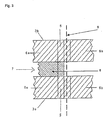
- FIG. 3 shows a variant of the support device according to the invention with support surfaces 6a and 6b.
- a part 8 that can be exchanged according to the width of the order. This area corresponds to the recess 5 in FIG. 2. If the nozzle outlet opening 2 is at the level of the dashed line 9, unintentionally escaping liquid cannot collect or deposit in the recess of the support device 3.
Landscapes
- Coating Apparatus (AREA)
Applications Claiming Priority (2)
| Application Number | Priority Date | Filing Date | Title |
|---|---|---|---|
| DE10208790 | 2002-02-28 | ||
| DE2002108790 DE10208790C1 (de) | 2002-02-28 | 2002-02-28 | Vorrichtung zum Auftragen von fließfähigen Stoffen |
Publications (2)
| Publication Number | Publication Date |
|---|---|
| EP1340552A2 true EP1340552A2 (fr) | 2003-09-03 |
| EP1340552A3 EP1340552A3 (fr) | 2005-11-09 |
Family
ID=27675125
Family Applications (1)
| Application Number | Title | Priority Date | Filing Date |
|---|---|---|---|
| EP02012003A Withdrawn EP1340552A3 (fr) | 2002-02-28 | 2002-05-31 | Dispositif d'application de produit fluide |
Country Status (2)
| Country | Link |
|---|---|
| EP (1) | EP1340552A3 (fr) |
| DE (1) | DE10208790C1 (fr) |
Cited By (1)
| Publication number | Priority date | Publication date | Assignee | Title |
|---|---|---|---|---|
| EP1669138A1 (fr) | 2004-12-09 | 2006-06-14 | hhs Leimauftrags-Systeme GmbH | Appareil pour l'application de produits fluides |
Families Citing this family (2)
| Publication number | Priority date | Publication date | Assignee | Title |
|---|---|---|---|---|
| DE102007057820C5 (de) | 2007-11-30 | 2020-07-16 | Windmöller & Hölscher Kg | Gegenlage Düsenbeleimung |
| DE102011110277A1 (de) | 2011-06-22 | 2012-12-27 | Baumer Hhs Gmbh | Verfahren und Vorrichtung zur Beeinflussung einerSubstratlage in Kombination mit einer Vorrichtung zumAbgeben eines Viskosen Mediums |
Citations (3)
| Publication number | Priority date | Publication date | Assignee | Title |
|---|---|---|---|---|
| DE9115872U1 (de) | 1991-12-20 | 1992-03-05 | hhs Leimauftrags-Systeme GmbH, 40885 Ratingen | Dosierventil zur Portionierung von fließfähigen Stoffen |
| DE4013323C2 (de) | 1990-04-26 | 1996-07-25 | Hhs Leimauftrags Systeme Gmbh | Dosierventil |
| DE29508916U1 (de) | 1995-06-02 | 1996-10-02 | hhs Leimauftrags-Systeme GmbH, 40885 Ratingen | Dosierventil |
Family Cites Families (6)
| Publication number | Priority date | Publication date | Assignee | Title |
|---|---|---|---|---|
| US3496012A (en) * | 1967-02-13 | 1970-02-17 | Mead Corp | Coating apparatus and method |
| US3902414A (en) * | 1970-10-01 | 1975-09-02 | Peter Zimmer | Screen printer using vibration to improve ink penetration |
| DE3315770A1 (de) * | 1983-04-30 | 1984-10-31 | Küsters, Eduard, 4150 Krefeld | Vorrichtung zum auftragen eines behandlungsmittels, insbesondere in schaumform, auf eine laufende warenbahn |
| DE3510147A1 (de) * | 1985-03-21 | 1986-09-25 | Carl Rückle Maschinenbau GmbH, 7302 Ostfildern | Vorrichtung zum beleimen streifenfoermiger flaechen zweier werkstuecke |
| AT384561B (de) * | 1985-05-03 | 1987-12-10 | Johannes Zimmer | Verfahren und vorrichtung zum auftragen fliessfaehiger substanzen |
| US4746545A (en) * | 1985-12-16 | 1988-05-24 | Acumeter Laboratories, Inc. | Fluid coating and web-handling method and apparatus particularly adapted for low-tension and/or unevenly thick webs |
-
2002
- 2002-02-28 DE DE2002108790 patent/DE10208790C1/de not_active Expired - Fee Related
- 2002-05-31 EP EP02012003A patent/EP1340552A3/fr not_active Withdrawn
Patent Citations (3)
| Publication number | Priority date | Publication date | Assignee | Title |
|---|---|---|---|---|
| DE4013323C2 (de) | 1990-04-26 | 1996-07-25 | Hhs Leimauftrags Systeme Gmbh | Dosierventil |
| DE9115872U1 (de) | 1991-12-20 | 1992-03-05 | hhs Leimauftrags-Systeme GmbH, 40885 Ratingen | Dosierventil zur Portionierung von fließfähigen Stoffen |
| DE29508916U1 (de) | 1995-06-02 | 1996-10-02 | hhs Leimauftrags-Systeme GmbH, 40885 Ratingen | Dosierventil |
Cited By (1)
| Publication number | Priority date | Publication date | Assignee | Title |
|---|---|---|---|---|
| EP1669138A1 (fr) | 2004-12-09 | 2006-06-14 | hhs Leimauftrags-Systeme GmbH | Appareil pour l'application de produits fluides |
Also Published As
| Publication number | Publication date |
|---|---|
| EP1340552A3 (fr) | 2005-11-09 |
| DE10208790C1 (de) | 2003-10-16 |
Similar Documents
| Publication | Publication Date | Title |
|---|---|---|
| EP0850697B1 (fr) | Dispositif pour l'application de matériaux fluides sur un substrat, en particulier pour l'application intermittente de colles fluides | |
| DE3430443A1 (de) | Schneidvorrichtung fuer papier- und folienbahnen, insbesondere fuer druckwerke, plotter, kopiergeraete und aehnliche maschinen | |
| DE202020102784U1 (de) | Ausgabemechanismus für Karten | |
| DE102016204311A1 (de) | Plattform-schneidvorrichtung | |
| EP1205257B1 (fr) | Dispositif d'application d'adhésif fluide sur un matériau en bande en mouvement par rapport au dispositif, en particulier sur une bande de rebord de meuble | |
| DE10208790C1 (de) | Vorrichtung zum Auftragen von fließfähigen Stoffen | |
| EP3377233A1 (fr) | Buse à rideau pour le revêtement d'un substrat, présentant une largeur de fente réglable | |
| DE4401737C1 (de) | Streicheinrichtung | |
| EP2517892A1 (fr) | Dispositif et procédé de fabrication d'un bloc de livre relié présentant une bande à onglets ou une couverture | |
| EP2324977A2 (fr) | Dispositif de collage de chants | |
| DE19711948C2 (de) | Vorrichtung in einer Druckmaschine zum Aufbringen von Leim | |
| EP3546070B1 (fr) | Dispositif d'application d'une matière coulante à un substrat | |
| DE2138628C3 (de) | Stapelmagazin für eine Vorrichtung zum Vereinzeln von Bogen | |
| DE102019122509A1 (de) | Vorrichtung zur Herstellung von Buchdecken, Schachteldecken oder Spielebrettern | |
| EP3936288B1 (fr) | Dispositif de découpe pour étiquettes à bande continue sans support auto-adhésives | |
| EP0190629B1 (fr) | Dispositif de séparation pour bandes de formulaires ou feuilles séparées dans les machines de bureau, en particulier des imprimantes matricielles | |
| EP1669138B1 (fr) | Appareil pour l'application de produits fluides | |
| DE3308066C1 (de) | Farbdosiervorrichtung fuer eine Farbkastenwalze | |
| EP0410400B1 (fr) | Dispositif pour l'alimentation en matériau de plieuses et dispositifs de mouillage dans des machines à imprimer | |
| AT390753B (de) | Fuehrung von flaechenmaterial in anlagen mit rundmessern | |
| EP1817159B1 (fr) | Procede et dispositif pour appliquer une substance adhesive sur un carton ondule | |
| DE9315499U1 (de) | Einrichtung zum Zumessen | |
| DE1261389B (de) | Haltevorrichtung fuer Messer zum Schneiden von flaechigem Material | |
| DE19544947A1 (de) | Vorrichtung zum Abrollen von zumindest einem Streifen, insbesondere Schleifpapier | |
| EP2213470A1 (fr) | Dispositif d'application d'un liquide le long d'une ligne de pliage |
Legal Events
| Date | Code | Title | Description |
|---|---|---|---|
| PUAI | Public reference made under article 153(3) epc to a published international application that has entered the european phase |
Free format text: ORIGINAL CODE: 0009012 |
|
| AK | Designated contracting states |
Kind code of ref document: A2 Designated state(s): AT BE CH CY DE DK ES FI FR GB GR IE IT LI LU MC NL PT SE TR |
|
| AX | Request for extension of the european patent |
Extension state: AL LT LV MK RO SI |
|
| PUAL | Search report despatched |
Free format text: ORIGINAL CODE: 0009013 |
|
| AK | Designated contracting states |
Kind code of ref document: A3 Designated state(s): AT BE CH CY DE DK ES FI FR GB GR IE IT LI LU MC NL PT SE TR |
|
| AX | Request for extension of the european patent |
Extension state: AL LT LV MK RO SI |
|
| STAA | Information on the status of an ep patent application or granted ep patent |
Free format text: STATUS: THE APPLICATION IS DEEMED TO BE WITHDRAWN |
|
| AKX | Designation fees paid | ||
| 18D | Application deemed to be withdrawn |
Effective date: 20051201 |
|
| REG | Reference to a national code |
Ref country code: DE Ref legal event code: 8566 |