EP1340569B1 - A method and unit for machining parts in a transfer type machine tool - Google Patents
A method and unit for machining parts in a transfer type machine tool Download PDFInfo
- Publication number
- EP1340569B1 EP1340569B1 EP03425115A EP03425115A EP1340569B1 EP 1340569 B1 EP1340569 B1 EP 1340569B1 EP 03425115 A EP03425115 A EP 03425115A EP 03425115 A EP03425115 A EP 03425115A EP 1340569 B1 EP1340569 B1 EP 1340569B1
- Authority
- EP
- European Patent Office
- Prior art keywords
- spindle
- machining
- length
- station
- bar
- Prior art date
- Legal status (The legal status is an assumption and is not a legal conclusion. Google has not performed a legal analysis and makes no representation as to the accuracy of the status listed.)
- Expired - Lifetime
Links
- 238000003754 machining Methods 0.000 title claims abstract description 64
- 238000000034 method Methods 0.000 title claims abstract description 17
- 238000005520 cutting process Methods 0.000 claims abstract description 11
- 238000005553 drilling Methods 0.000 claims description 4
- 238000003801 milling Methods 0.000 claims description 4
- 230000001360 synchronised effect Effects 0.000 description 2
- 238000012986 modification Methods 0.000 description 1
- 230000004048 modification Effects 0.000 description 1
Images
Classifications
-
- B—PERFORMING OPERATIONS; TRANSPORTING
- B23—MACHINE TOOLS; METAL-WORKING NOT OTHERWISE PROVIDED FOR
- B23Q—DETAILS, COMPONENTS, OR ACCESSORIES FOR MACHINE TOOLS, e.g. ARRANGEMENTS FOR COPYING OR CONTROLLING; MACHINE TOOLS IN GENERAL CHARACTERISED BY THE CONSTRUCTION OF PARTICULAR DETAILS OR COMPONENTS; COMBINATIONS OR ASSOCIATIONS OF METAL-WORKING MACHINES, NOT DIRECTED TO A PARTICULAR RESULT
- B23Q39/00—Metal-working machines incorporating a plurality of sub-assemblies, each capable of performing a metal-working operation
- B23Q39/04—Metal-working machines incorporating a plurality of sub-assemblies, each capable of performing a metal-working operation the sub-assemblies being arranged to operate simultaneously at different stations, e.g. with an annular work-table moved in steps
- B23Q39/048—Metal-working machines incorporating a plurality of sub-assemblies, each capable of performing a metal-working operation the sub-assemblies being arranged to operate simultaneously at different stations, e.g. with an annular work-table moved in steps the work holder of a work station transfers directly its workpiece to the work holder of a following work station
-
- B—PERFORMING OPERATIONS; TRANSPORTING
- B23—MACHINE TOOLS; METAL-WORKING NOT OTHERWISE PROVIDED FOR
- B23Q—DETAILS, COMPONENTS, OR ACCESSORIES FOR MACHINE TOOLS, e.g. ARRANGEMENTS FOR COPYING OR CONTROLLING; MACHINE TOOLS IN GENERAL CHARACTERISED BY THE CONSTRUCTION OF PARTICULAR DETAILS OR COMPONENTS; COMBINATIONS OR ASSOCIATIONS OF METAL-WORKING MACHINES, NOT DIRECTED TO A PARTICULAR RESULT
- B23Q7/00—Arrangements for handling work specially combined with or arranged in, or specially adapted for use in connection with, machine tools, e.g. for conveying, loading, positioning, discharging, sorting
- B23Q7/02—Arrangements for handling work specially combined with or arranged in, or specially adapted for use in connection with, machine tools, e.g. for conveying, loading, positioning, discharging, sorting by means of drums or rotating tables or discs
-
- B—PERFORMING OPERATIONS; TRANSPORTING
- B23—MACHINE TOOLS; METAL-WORKING NOT OTHERWISE PROVIDED FOR
- B23Q—DETAILS, COMPONENTS, OR ACCESSORIES FOR MACHINE TOOLS, e.g. ARRANGEMENTS FOR COPYING OR CONTROLLING; MACHINE TOOLS IN GENERAL CHARACTERISED BY THE CONSTRUCTION OF PARTICULAR DETAILS OR COMPONENTS; COMBINATIONS OR ASSOCIATIONS OF METAL-WORKING MACHINES, NOT DIRECTED TO A PARTICULAR RESULT
- B23Q7/00—Arrangements for handling work specially combined with or arranged in, or specially adapted for use in connection with, machine tools, e.g. for conveying, loading, positioning, discharging, sorting
- B23Q7/04—Arrangements for handling work specially combined with or arranged in, or specially adapted for use in connection with, machine tools, e.g. for conveying, loading, positioning, discharging, sorting by means of grippers
Definitions
- the present invention relates to a method and unit for machining parts in a transfer type machine tool, according to the preamble of claim 1 and claim 11 respectively (see, for example, EP-0 936 027 - A).
- the present invention relates to transfer type machine tools with a rotary table, in which the parts to be subjected to various types of mechanical machining are carried in succession into a plurality of machining stations where various machining units work on them by a rotary table, to which they are fixed by locking means.
- machine tools of this type have a supporting base for the machining units, arranged around the rotary table and the number of locking elements is normally equal to that of the machining stations, allowing simultaneous machining on a plurality of parts.
- the first machining station is a loading station, where the part to be machined is fixed to one of the locking elements.
- the rotary table then carries the part through the various machining stations to an unloading station, where the locking means release the finished part.
- machining units arranged around the rotary table cannot perform an entire machining cycle on parts.
- turning operations are performed beforehand, using a lathe outside the machine tool in question, after the parts have been separated from a bar by means of a cutting operation.
- a primary spindle On machine tools of this type, next to the loading station there is a primary spindle whose longitudinal axis is parallel with the axis of the rotary table and which is supported by a load-bearing body that moves along a feed axis parallel with the above-mentioned axes.
- the bar is locked so that the end to be processed and made into a finished product with a succession of machining operations projects outside the spindle.
- the primary spindle to which the bar is rigidly attached, is rotated and moved forward by the load-bearing body along the feed axis and towards a tool holder carriage which moves in two directions transversal to the feed axis. In this way it carries the above-mentioned end of the bar to a given tool, which performs the turning.
- a secondary spindle or counter-spindle mounted on a two-axis module, moves along an axis aligned with the primary spindle feed axis, coming alongside the end of the bar, and at the same time is made to rotate about this axis until it reaches the same speed of rotation as the primary spindle.
- the primary and secondary spindles rotate in a synchronised fashion, allowing cutting means to detach the end from the bar.
- the part is locked on the secondary spindle, which stops rotating.
- the primary spindle is now free to release the bar and feed means of the known type feed the bar longitudinally over a given length corresponding to a new part.
- the secondary spindle When the secondary spindle has stopped rotating, it transfers the part to one of the locking elements on the rotary table, which carries the part to the successive machining steps at the machining units.
- any machining operations to be performed on the end of the part inserted in the primary spindle and for which strict observation of the coaxial and concentric tolerances is required are currently performed at one of the machining stations on the rotary table, and in such cases part positioning by the above-mentioned fixing elements relative to the tool does not provide the same precision as can be achieved with the primary spindle.
- the aim of the present invention is to produce a transfer type machine tool which is free of the above-mentioned disadvantages.
- the present invention provides a method as defined in claim 1.
- the present invention also relates to a unit for machining parts as defined in claim 11.
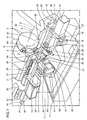
- the numeral 1 denotes as a whole a portion of a transfer type machine tool equipped with a unit 2 for machining parts 3.
- the portion of machine 1 comprises a base 4 supporting the unit 2 which comprises a table 5 that rotates about a substantially horizontal axis of rotation 6 driven by a motor 7.
- the table 5 has a substantially cylindrical body 8 with, along its outer cylindrical surface, a plurality of pick up and locking parts 9 mounted at equal angular intervals from each other.
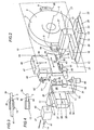
- the unit 2 comprises, on opposite sides of a vertical plane 10 (illustrated in Figure 2) in which the rotary table 5 lies, a first and a second machining station, labelled, respectively, 11 and 12 from left to right in Figures 1 and 2.
- first spindle 13 which is rotationally driven by a motor 15 about an axis 14 parallel with the axis 6.
- second spindle 16 which is rotationally driven by a motor 18 about an axis 17 parallel with the axis 14.
- a first supporting and driving module 19 is attached to the second spindle 16. The module is, in turn, supported by an upright 20 on the base 4.
- the first module 19 comprises a first slide 21 supporting the second spindle 16 which is mobile in both directions, transversally to the axis 17, along a path 22 on a sliding surface 23 formed by the upper face of a second slide 24, also mobile in both directions, parallel with the axis 17, along a path 25 on a sliding surface 26 formed by the top of the upright 20.
- a second supporting and driving module 27 is attached to the first spindle 13.
- the second module comprises a slide 28 which runs along the axis 14, in both directions and driven by a motor 29, along a guide 30 supported by the base 4.
- first tool means 31 comprising a supporting carriage 32, in turn supported by the base 4 and consisting of a first slide 33 supporting a plurality of tools 34.
- the first slide 33 moves both ways in a vertical direction 35 along a guide 36 made on one side of a second slide 37, in turn moving, in a transversal direction 38 to the axis 14 along a guide 39 supported by the base 4.
- a bar 41 is fed with intermittent motion to the first spindle 13 by feed means 40, of the known type and illustrated in Figure 1 by a simple block.
- feed means 40 of the known type and illustrated in Figure 1 by a simple block. The methods described below are used to perform a cutting operation to obtain from the bar the individual parts 3 to be machined.
- the feed means 40 feed the bar 41 into the first spindle 13, feeding it along the axis 14 by a length which leaves one end of the bar 41 projecting beyond the mouth 42 of the spindle 13 by a first given length which, as illustrated in Figure 3 is just over the length of a part 3.
- the motor 15 causes the first spindle 13 to rotate and the carriage 32, by means of its slides 33 and 37, driven by respective motors, not illustrated and of the known type, moves a selected tool 34 to the length of the bar 41 projecting from the mouth 42 of the spindle 13 to perform a turning operation on at least one end portion of the bar 41. It should be noticed that a portion 3b close to the mouth 42 of the spindle 13, due to obvious problems caused by interference between the tool 34 and the spindle 13, is excluded from this first turning operation.
- second tool means labelled 43 as a whole, which, with the methods more clearly described below, perform a second turning operation on the portion 3b of the part 3 obtained by cutting.
- the tool means 43 comprise a carriage 44 supported, as illustrated in Figure 1, by a substantially vertical wall 45 of the base 4.
- the carriage 44 comprises a slide 46 which moves both ways in a vertical direction 47 along a guide 48 (see Figure 1) made on the vertical wall 45.
- the carriage 32 draws back the tools 34 and 49 to a home position.
- the first and second spindles 13, 16 positioned symmetrically relative to the plane 10 in which the rotary table 5 lies, move alongside one another along the axes 14 and 17 aligned with one another.
- the motor 18 of the second spindle 16 makes the latter rotate about its axis 17 at a speed synchronised with the speed of rotation of the first spindle 13, using synchronising means represented by a block 50, which make the electrical connection between the motors 15 and 18 (see Figure 1).
- the second spindle 16 When it has reached the free end of the length of the bar 42 projecting from the first spindle 13 and previously machined, the second spindle 16 receives a length of the portion previously machined in the first station 11 in its mouth 54 and grips it.
- a cutting tool, labelled 51 in Figure 2 simultaneously moves both ways in a vertical direction 52, transversally to the axis 14 and substantially at a tangent to the mouth 42 of the first spindle 13, and in another, substantially horizontal direction 52a, so that it separates from the bar 41, rotated by the first spindle 13, the length of the bar 41 projecting from the mouth 42 of the spindle 13, thus forming a part 3.
- the second spindle 16 performing its return stroke substantially along the axis 17 away from the first station 11, arrives at the second machining station 12, where an appropriate tool 53 which is part of the second tool means 43 is brought by the carriage 44 into contact with the portion 3b not previously machined, to perform turning on this portion.
- the portion 3b of the part 3 may also be subjected to other drilling and/or milling and/or boring operations using other types of tools, also part of the tool means 43.
- a tool change-over operation is possible because the tool means 43, such as an electrospindle 55 supported by a bracket 56, are mounted on a slide 57 supported by the lower end of the carriage 44 and can be moved both ways by alternative drive means of the known type and not illustrated, in a direction 58 transversal to the axis 17 of the second spindle 16.
- the part 3 When the second machining operation on the portion 3b is complete, the part 3, by means of suitable movements by the first and second slides 21 and 24 of the first module 19, is released by the second spindle 16, at a loading station 59, and transferred to the pick up and locking parts 9 on the body 8 of the rotary table 5.
- the table rotating clockwise about its axis 6 as illustrated in Figure 2, carries the part 3 through a plurality of machining stations, at which a plurality of machining units, not illustrated, perform additional machining on the part 3, then to an unloading station 60 for each finished part 3.
- the first spindle 13 is fed not with bars 41, but with sections of bar labelled 61 in Figure 1 forming the parts 3 to be machined.
- the parts 3 are fed one at a time to the first spindle 13 by second feed means, illustrated with a block labelled 62, so that, as illustrated in Figure 4, a length of the part 3 shorter than the part 3 projects from the mouth 42 of the spindle 13, since a short length of the part must form a portion of the part 3 to be gripped by the spindle 13.
- the parts 3 being the same length as those of the embodiment described above, the portion 3a machinable at the first machining station 11 is smaller whilst, obviously the portion 3b to be machined at the second machining station 12 is bigger.
- the unit 2 since the unit 2 has two separate machining stations equipped with respective tool holder carriages and positioned symmetrically relative to the plane 10 in which the rotary table 5 lies, the productivity of the unit 2 is higher than that of prior art units, since two parts 3 can be machined and even turned simultaneously.
- the sections 61 may be fed to the unit 2 by the rotary head 5, which could pick up the sections 61 from a pick up station using the pick up and locking means 9 and carry them to the machining station 11.
- the second spindle 16 can be fitted with a tailstock for machining narrow parts 3 which are rotated by the first spindle 13. When the turning is complete, the second spindle 16 repositions the tailstock on the carriage 44.
Landscapes
- Engineering & Computer Science (AREA)
- Mechanical Engineering (AREA)
- Turning (AREA)
- Feeding Of Workpieces (AREA)
- Multi-Process Working Machines And Systems (AREA)
- Drilling And Boring (AREA)
- Machine Tool Positioning Apparatuses (AREA)
- Automatic Tool Replacement In Machine Tools (AREA)
Applications Claiming Priority (2)
| Application Number | Priority Date | Filing Date | Title |
|---|---|---|---|
| IT2002BO000099A ITBO20020099A1 (it) | 2002-02-28 | 2002-02-28 | Metodo ed unita per la lavorazione di pezzi in una macchina utensile di tipo transfer |
| ITBO20020099 | 2002-02-28 |
Publications (3)
| Publication Number | Publication Date |
|---|---|
| EP1340569A2 EP1340569A2 (en) | 2003-09-03 |
| EP1340569A3 EP1340569A3 (en) | 2003-11-05 |
| EP1340569B1 true EP1340569B1 (en) | 2005-04-27 |
Family
ID=11439945
Family Applications (1)
| Application Number | Title | Priority Date | Filing Date |
|---|---|---|---|
| EP03425115A Expired - Lifetime EP1340569B1 (en) | 2002-02-28 | 2003-02-24 | A method and unit for machining parts in a transfer type machine tool |
Country Status (4)
| Country | Link |
|---|---|
| EP (1) | EP1340569B1 (it) |
| AT (1) | ATE294041T1 (it) |
| DE (1) | DE60300551T2 (it) |
| IT (1) | ITBO20020099A1 (it) |
Families Citing this family (1)
| Publication number | Priority date | Publication date | Assignee | Title |
|---|---|---|---|---|
| EP1632309B1 (fr) * | 2004-09-06 | 2007-06-20 | Tornos SA | Dispositif d'usinage en contre-opération dans un tour multibroches |
Family Cites Families (5)
| Publication number | Priority date | Publication date | Assignee | Title |
|---|---|---|---|---|
| US5020402A (en) * | 1986-10-09 | 1991-06-04 | Index-Werke Kg | Method and apparatus for machining both sides of workpieces |
| JPH0716804B2 (ja) * | 1988-11-30 | 1995-03-01 | スター精密株式会社 | 主軸摺動型自動旋盤およびこれを用いた加工方法 |
| DE19529071C2 (de) * | 1995-08-08 | 1998-04-30 | Holger Wuerthner | Vorrichtung zur Front- und Rückseitenbearbeitung von Werkstücken |
| EP0936027B1 (fr) * | 1998-02-12 | 2003-05-07 | Tornos SA | Dispositif d'usinage en contre-opération pour une machine-outil |
| IT1305099B1 (it) * | 1998-12-30 | 2001-04-10 | Skf Ab | Procedimento per la lavorazione di pezzi e tornio a controllo numerico |
-
2002
- 2002-02-28 IT IT2002BO000099A patent/ITBO20020099A1/it unknown
-
2003
- 2003-02-24 AT AT03425115T patent/ATE294041T1/de not_active IP Right Cessation
- 2003-02-24 DE DE60300551T patent/DE60300551T2/de not_active Expired - Lifetime
- 2003-02-24 EP EP03425115A patent/EP1340569B1/en not_active Expired - Lifetime
Also Published As
| Publication number | Publication date |
|---|---|
| ATE294041T1 (de) | 2005-05-15 |
| EP1340569A3 (en) | 2003-11-05 |
| DE60300551D1 (de) | 2005-06-02 |
| DE60300551T2 (de) | 2006-05-04 |
| ITBO20020099A1 (it) | 2003-08-28 |
| EP1340569A2 (en) | 2003-09-03 |
| ITBO20020099A0 (it) | 2002-02-28 |
Similar Documents
| Publication | Publication Date | Title |
|---|---|---|
| US5093978A (en) | Manipulator for tools and tool adapters | |
| EP0806998B1 (en) | Machine tool with horizontal spindles | |
| US5832590A (en) | System for machining workpieces | |
| US5704262A (en) | Multiple-spindle lathe | |
| EP1155764B1 (en) | Combined nc lathe | |
| CN105579192B (zh) | 具有多个多主轴-主轴总成的机床 | |
| US6920679B2 (en) | Machine tool | |
| US9211621B2 (en) | Machining apparatus | |
| US4987807A (en) | Multispindle lathe | |
| CN110899755B (zh) | 一种多工位数控钻孔中心 | |
| EP2163334B1 (en) | Machine comprising a drum having workpiece supporting spindles movable in the direction of the longitudinal axis of the drum | |
| CN103128601A (zh) | 用于加工轴形工件的机床 | |
| US20180354089A1 (en) | Machine tool for machining a workpiece | |
| US20130340242A1 (en) | Method and apparatus for complete machining of a shaft-shaped workpiece | |
| US3932924A (en) | Method of changing tools | |
| US7008152B2 (en) | Machine tool for processing work pieces on at least three axes | |
| US6964217B2 (en) | Multispindle lathe | |
| CN104959630B (zh) | 一种8轴全自动车珠机及加工方法 | |
| JPWO2009060579A1 (ja) | 工作機械 | |
| EP1340569B1 (en) | A method and unit for machining parts in a transfer type machine tool | |
| JPH01228701A (ja) | 工作機械 | |
| US4868960A (en) | Transfer machine | |
| CN119282790A (zh) | 一种带y结构的大孔径走心机 | |
| WO2024209775A1 (ja) | チャック、ローダ装置、及び工作機械 | |
| JP5275663B2 (ja) | 異形断面バー材の供給装置及び加工装置 |
Legal Events
| Date | Code | Title | Description |
|---|---|---|---|
| PUAI | Public reference made under article 153(3) epc to a published international application that has entered the european phase |
Free format text: ORIGINAL CODE: 0009012 |
|
| AK | Designated contracting states |
Kind code of ref document: A2 Designated state(s): AT BE BG CH CY CZ DE DK EE ES FI FR GB GR HU IE IT LI LU MC NL PT SE SI SK TR |
|
| AX | Request for extension of the european patent |
Extension state: AL LT LV MK RO |
|
| PUAL | Search report despatched |
Free format text: ORIGINAL CODE: 0009013 |
|
| AK | Designated contracting states |
Kind code of ref document: A3 Designated state(s): AT BE BG CH CY CZ DE DK EE ES FI FR GB GR HU IE IT LI LU MC NL PT SE SI SK TR |
|
| AX | Request for extension of the european patent |
Extension state: AL LT LV MK RO |
|
| 17P | Request for examination filed |
Effective date: 20031215 |
|
| 17Q | First examination report despatched |
Effective date: 20040422 |
|
| AKX | Designation fees paid |
Designated state(s): AT BE BG CH CY CZ DE DK EE ES FI FR GB GR HU IE IT LI LU MC NL PT SE SI SK TR |
|
| GRAP | Despatch of communication of intention to grant a patent |
Free format text: ORIGINAL CODE: EPIDOSNIGR1 |
|
| GRAS | Grant fee paid |
Free format text: ORIGINAL CODE: EPIDOSNIGR3 |
|
| GRAA | (expected) grant |
Free format text: ORIGINAL CODE: 0009210 |
|
| AK | Designated contracting states |
Kind code of ref document: B1 Designated state(s): AT BE BG CH CY CZ DE DK EE ES FI FR GB GR HU IE IT LI LU MC NL PT SE SI SK TR |
|
| PG25 | Lapsed in a contracting state [announced via postgrant information from national office to epo] |
Ref country code: SK Free format text: LAPSE BECAUSE OF FAILURE TO SUBMIT A TRANSLATION OF THE DESCRIPTION OR TO PAY THE FEE WITHIN THE PRESCRIBED TIME-LIMIT Effective date: 20050427 Ref country code: FI Free format text: LAPSE BECAUSE OF FAILURE TO SUBMIT A TRANSLATION OF THE DESCRIPTION OR TO PAY THE FEE WITHIN THE PRESCRIBED TIME-LIMIT Effective date: 20050427 Ref country code: SI Free format text: LAPSE BECAUSE OF FAILURE TO SUBMIT A TRANSLATION OF THE DESCRIPTION OR TO PAY THE FEE WITHIN THE PRESCRIBED TIME-LIMIT Effective date: 20050427 Ref country code: AT Free format text: LAPSE BECAUSE OF FAILURE TO SUBMIT A TRANSLATION OF THE DESCRIPTION OR TO PAY THE FEE WITHIN THE PRESCRIBED TIME-LIMIT Effective date: 20050427 Ref country code: CZ Free format text: LAPSE BECAUSE OF FAILURE TO SUBMIT A TRANSLATION OF THE DESCRIPTION OR TO PAY THE FEE WITHIN THE PRESCRIBED TIME-LIMIT Effective date: 20050427 Ref country code: BE Free format text: LAPSE BECAUSE OF FAILURE TO SUBMIT A TRANSLATION OF THE DESCRIPTION OR TO PAY THE FEE WITHIN THE PRESCRIBED TIME-LIMIT Effective date: 20050427 Ref country code: NL Free format text: LAPSE BECAUSE OF FAILURE TO SUBMIT A TRANSLATION OF THE DESCRIPTION OR TO PAY THE FEE WITHIN THE PRESCRIBED TIME-LIMIT Effective date: 20050427 |
|
| REG | Reference to a national code |
Ref country code: GB Ref legal event code: FG4D |
|
| REG | Reference to a national code |
Ref country code: CH Ref legal event code: EP |
|
| REG | Reference to a national code |
Ref country code: IE Ref legal event code: FG4D |
|
| REF | Corresponds to: |
Ref document number: 60300551 Country of ref document: DE Date of ref document: 20050602 Kind code of ref document: P |
|
| REG | Reference to a national code |
Ref country code: CH Ref legal event code: NV Representative=s name: BUGNION S.A. |
|
| PG25 | Lapsed in a contracting state [announced via postgrant information from national office to epo] |
Ref country code: GR Free format text: LAPSE BECAUSE OF FAILURE TO SUBMIT A TRANSLATION OF THE DESCRIPTION OR TO PAY THE FEE WITHIN THE PRESCRIBED TIME-LIMIT Effective date: 20050727 Ref country code: DK Free format text: LAPSE BECAUSE OF FAILURE TO SUBMIT A TRANSLATION OF THE DESCRIPTION OR TO PAY THE FEE WITHIN THE PRESCRIBED TIME-LIMIT Effective date: 20050727 Ref country code: SE Free format text: LAPSE BECAUSE OF FAILURE TO SUBMIT A TRANSLATION OF THE DESCRIPTION OR TO PAY THE FEE WITHIN THE PRESCRIBED TIME-LIMIT Effective date: 20050727 Ref country code: BG Free format text: LAPSE BECAUSE OF FAILURE TO SUBMIT A TRANSLATION OF THE DESCRIPTION OR TO PAY THE FEE WITHIN THE PRESCRIBED TIME-LIMIT Effective date: 20050727 |
|
| PG25 | Lapsed in a contracting state [announced via postgrant information from national office to epo] |
Ref country code: HU Free format text: LAPSE BECAUSE OF FAILURE TO SUBMIT A TRANSLATION OF THE DESCRIPTION OR TO PAY THE FEE WITHIN THE PRESCRIBED TIME-LIMIT Effective date: 20050728 |
|
| PG25 | Lapsed in a contracting state [announced via postgrant information from national office to epo] |
Ref country code: ES Free format text: LAPSE BECAUSE OF FAILURE TO SUBMIT A TRANSLATION OF THE DESCRIPTION OR TO PAY THE FEE WITHIN THE PRESCRIBED TIME-LIMIT Effective date: 20050807 |
|
| PG25 | Lapsed in a contracting state [announced via postgrant information from national office to epo] |
Ref country code: PT Free format text: LAPSE BECAUSE OF FAILURE TO SUBMIT A TRANSLATION OF THE DESCRIPTION OR TO PAY THE FEE WITHIN THE PRESCRIBED TIME-LIMIT Effective date: 20051010 |
|
| NLV1 | Nl: lapsed or annulled due to failure to fulfill the requirements of art. 29p and 29m of the patents act | ||
| PG25 | Lapsed in a contracting state [announced via postgrant information from national office to epo] |
Ref country code: IE Free format text: LAPSE BECAUSE OF NON-PAYMENT OF DUE FEES Effective date: 20060224 |
|
| PG25 | Lapsed in a contracting state [announced via postgrant information from national office to epo] |
Ref country code: MC Free format text: LAPSE BECAUSE OF NON-PAYMENT OF DUE FEES Effective date: 20060228 Ref country code: LU Free format text: LAPSE BECAUSE OF NON-PAYMENT OF DUE FEES Effective date: 20060228 |
|
| PLBE | No opposition filed within time limit |
Free format text: ORIGINAL CODE: 0009261 |
|
| STAA | Information on the status of an ep patent application or granted ep patent |
Free format text: STATUS: NO OPPOSITION FILED WITHIN TIME LIMIT |
|
| ET | Fr: translation filed | ||
| 26N | No opposition filed |
Effective date: 20060130 |
|
| REG | Reference to a national code |
Ref country code: IE Ref legal event code: MM4A |
|
| PG25 | Lapsed in a contracting state [announced via postgrant information from national office to epo] |
Ref country code: EE Free format text: LAPSE BECAUSE OF FAILURE TO SUBMIT A TRANSLATION OF THE DESCRIPTION OR TO PAY THE FEE WITHIN THE PRESCRIBED TIME-LIMIT Effective date: 20050427 |
|
| PG25 | Lapsed in a contracting state [announced via postgrant information from national office to epo] |
Ref country code: TR Free format text: LAPSE BECAUSE OF FAILURE TO SUBMIT A TRANSLATION OF THE DESCRIPTION OR TO PAY THE FEE WITHIN THE PRESCRIBED TIME-LIMIT Effective date: 20050427 |
|
| PG25 | Lapsed in a contracting state [announced via postgrant information from national office to epo] |
Ref country code: CY Free format text: LAPSE BECAUSE OF FAILURE TO SUBMIT A TRANSLATION OF THE DESCRIPTION OR TO PAY THE FEE WITHIN THE PRESCRIBED TIME-LIMIT Effective date: 20050427 |
|
| PGFP | Annual fee paid to national office [announced via postgrant information from national office to epo] |
Ref country code: GB Payment date: 20090319 Year of fee payment: 7 |
|
| PGFP | Annual fee paid to national office [announced via postgrant information from national office to epo] |
Ref country code: FR Payment date: 20090224 Year of fee payment: 7 |
|
| GBPC | Gb: european patent ceased through non-payment of renewal fee |
Effective date: 20100224 |
|
| REG | Reference to a national code |
Ref country code: FR Ref legal event code: ST Effective date: 20101029 |
|
| PG25 | Lapsed in a contracting state [announced via postgrant information from national office to epo] |
Ref country code: FR Free format text: LAPSE BECAUSE OF NON-PAYMENT OF DUE FEES Effective date: 20100301 |
|
| PG25 | Lapsed in a contracting state [announced via postgrant information from national office to epo] |
Ref country code: GB Free format text: LAPSE BECAUSE OF NON-PAYMENT OF DUE FEES Effective date: 20100224 |
|
| PGFP | Annual fee paid to national office [announced via postgrant information from national office to epo] |
Ref country code: DE Payment date: 20220224 Year of fee payment: 20 Ref country code: CH Payment date: 20220225 Year of fee payment: 20 |
|
| PGFP | Annual fee paid to national office [announced via postgrant information from national office to epo] |
Ref country code: IT Payment date: 20220214 Year of fee payment: 20 |
|
| REG | Reference to a national code |
Ref country code: DE Ref legal event code: R071 Ref document number: 60300551 Country of ref document: DE |
|
| REG | Reference to a national code |
Ref country code: CH Ref legal event code: PL |