EP1340603B1 - Sägevorrichtung - Google Patents
Sägevorrichtung Download PDFInfo
- Publication number
- EP1340603B1 EP1340603B1 EP02028674A EP02028674A EP1340603B1 EP 1340603 B1 EP1340603 B1 EP 1340603B1 EP 02028674 A EP02028674 A EP 02028674A EP 02028674 A EP02028674 A EP 02028674A EP 1340603 B1 EP1340603 B1 EP 1340603B1
- Authority
- EP
- European Patent Office
- Prior art keywords
- stop
- saw
- saw table
- sawing
- adjusting device
- Prior art date
- Legal status (The legal status is an assumption and is not a legal conclusion. Google has not performed a legal analysis and makes no representation as to the accuracy of the status listed.)
- Expired - Lifetime
Links
- 230000000717 retained effect Effects 0.000 claims 1
- 230000001419 dependent effect Effects 0.000 description 1
- 238000009434 installation Methods 0.000 description 1
- 238000003754 machining Methods 0.000 description 1
- 238000004519 manufacturing process Methods 0.000 description 1
- 238000000926 separation method Methods 0.000 description 1
Images


Classifications
-
- B—PERFORMING OPERATIONS; TRANSPORTING
- B27—WORKING OR PRESERVING WOOD OR SIMILAR MATERIAL; NAILING OR STAPLING MACHINES IN GENERAL
- B27B—SAWS FOR WOOD OR SIMILAR MATERIAL; COMPONENTS OR ACCESSORIES THEREFOR
- B27B27/00—Guide fences or stops for timber in saw mills or sawing machines; Measuring equipment thereon
- B27B27/10—Devices for moving or adjusting the guide fences or stops
-
- B—PERFORMING OPERATIONS; TRANSPORTING
- B27—WORKING OR PRESERVING WOOD OR SIMILAR MATERIAL; NAILING OR STAPLING MACHINES IN GENERAL
- B27B—SAWS FOR WOOD OR SIMILAR MATERIAL; COMPONENTS OR ACCESSORIES THEREFOR
- B27B27/00—Guide fences or stops for timber in saw mills or sawing machines; Measuring equipment thereon
- B27B27/04—Guide fences or stops for timber in saw mills or sawing machines; Measuring equipment thereon arranged perpendicularly to the plane of the saw blade
Definitions
- the invention relates to a sawing device according to the preamble of the claim 1.
- Sawing devices of the type in question have a saw table, which in the rule is designed to be stable and forms the base frame of the sawing device (DE 40 10 456 C2).
- the saw table usually has a workpiece support surface on which the workpiece to be machined rests.
- the attacks can be in their dimensions, their shape or differ in their structural design. At least the effort for the replacement of the attacks to keep low, has a other known sawing device exchangeable stops on, which with mounting brackets on the actual stops, which are fixed on the saw table, can be plugged (DE 90 03 773 U 1).
- the stop on the saw table is only in a fixed Position mountable (US 5,816,129 A).
- the stop faces one Stop body slidable and swiveling stop rails on.
- the invention is based on the problem, the known sawing device such to design and develop that the interchangeability of the attacks in Constant manufacturing accuracy is given without considerable effort.
- the present problem is solved by a sawing device with the Features of the preamble of claim 1 by the features of the characterizing Part of claim 1 solved.
- an adjustable adjusting device for fine positioning the stop is provided on the saw table, their setting during disassembly and the mounting of the stop retains.
- Such an adjusting device configured has the advantage that during disassembly and subsequent Mounting, or when changing the stop no re-fine positioning is required.
- the adjusting device is separated from a fastening device of the stop on the stop itself arranged. With the separation between the adjusting device and fastening device is achieved that expended in the attachment forces are not on the Einstillung affect the adjusting device.
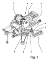
- Fig. 1 shows the overall structure of the sawing device according to the invention.
- the sawing device has a saw table 1, which in this case represents the base frame and a workpiece support surface 2. Arranged on the saw table 1 and mechanically coupled to the saw unit 3. Next is on the saw table 1 a substantially over the width of the saw table 1 extending stop 4 provided.
- the saw unit 3 has a rotatable about a rotation axis 5 Saw blade 6, which is driven by an electric motor 7.
- the saw unit 3 is in the present case extending parallel to the axis of rotation 5 of the saw blade 6 Swivel axis 8 swiveling. This is the design the sawing device as a chop saw.
- a workpiece is brought into contact with the stop 4 for machining, so that the workpiece has a clear alignment with respect to the saw blade 6.
- the stop 4 is connected by a fastening device 9 with the saw table. 1 releasably connected.
- the fastening device 9 is in the embodiment 1 realized as a screw, wherein the screw connection stop side has a slot. This slot has just enough game on that a fine positioning of the stopper 4 is possible.
- an adjusting device 10 is provided, which is configured separately from the fastening device 9.
- the special Advantage of this separate embodiment of fastening device 9 and Adjusting device 10 is that the powerful operation of the fastening device 9, the adjustment of the adjusting device 10 is not affected.
- the adjusting device 10 is arranged on the stop 4. But it can also be provided that the adjusting device 10 on Saw table 1 is provided, then, however, must be accepted that only a single adjustment of the adjusting device 10 for all substitutes Stops 4 is possible.
- the adjusting device 10 at least one adjusting screw 11, which in a stop 4 arranged threaded hole is screwed.
- Fig. 2 shows how the in the drawing right end of the adjusting screw 11 in contact with the saw table. 1 comes so that when mounted stop 4, the fine positioning of the stop 4 in the plane of the workpiece support surface 2 is possible.
- the adjusting screw 11 has a supporting function, so that forces on the adjusting screw 11 are transmitted or that the adjusting screw 11 only in such a way comes in contact with the saw table 1 that they are at fixed stop 4 substantially is free from forces.
- Fig. 3 shows the stop 4 of the sawing device according to the invention in perspective View.
- the adjustment device 10 here are two screws 11 are provided, which are each arranged on one end side of the stopper 4 (in Fig. 3, only the threaded holes can be seen).
- this two-sided Arrangement of the adjusting screws 11 is an optimal fine positioning given over the entire length of the attack 4.
- only one adjusting screw 11 is provided is, which is preferably arranged on one of the two end sides of the stopper 4 is.
- the adjusting screw 11 is designed to be self-locking, or that the adjusting screw 11 provided with a corresponding lock nut. Especially against the background, that the adjustment of the adjusting device 10 during disassembly and subsequent installation of the stop 4 is to be maintained, this is special advantageous.
- the stop 4 extends substantially over the width of the Saw Table 1. Basically, it should be noted that according to the invention also any Further dimensions and geometric configurations of the stop 4 possible are.
- clamp connections such as For example, an eccentric clamping device, are here for a trouble Disassembly and assembly provided.
- the stop 4 of the sawing device according to the invention can also be used as a component be provided a Schmiege.
- the Schmiege has one Schmiegekinematik on, with the two stops 4 are detachably connected.
- the Schmiegekinematik allows pivoting of the stops 4 such that the bisecting line in the space between the stops 4 always constant remains.
- an adjusting device 10 is provided, the above Preferences are now transferred to the Schmiege.
- a sawing device in question with a stop 4 which assigned a unique position on the saw table 1 is, in addition, a bend with a kinking kinematics and two strokes has, with the Schmiege associated attacks with the Schmiegekinematik are detachably connectable. It is envisaged that the stationary stop 4 and the Schmiege associated attacks depending on the application be used alternately.
Landscapes
- Life Sciences & Earth Sciences (AREA)
- Engineering & Computer Science (AREA)
- Mechanical Engineering (AREA)
- Wood Science & Technology (AREA)
- Forests & Forestry (AREA)
- Sawing (AREA)
- Inorganic Insulating Materials (AREA)
- Polishing Bodies And Polishing Tools (AREA)
- Thermistors And Varistors (AREA)
- Mechanical Treatment Of Semiconductor (AREA)
Description
- Fig. 1
- eine Gesamtansicht der erfindungsgemäßen Sägevorrichtung,
- Fig. 2
- eine Seitenansicht der Sägevorrichtung aus Fig. 1,
- Fig. 3
- eine perspektivische Ansicht des Anschlags der Sägevorrichtung aus Fig. 1
Claims (8)
- Sägevorrichtung mit einem Sägetisch (1), einem am Sägetisch (1) angeordneten Sägeaggregat (3) und mindestens einem Anschlag (4),
wobei das Sägeaggregat (3) ein um eine Drehachse (5) drehbares Sägeblatt (6) aufweist,
wobei das Sägeaggregat (3) vorzugsweise um eine parallel zur Drehachse (5) des Sägeblatts (6) verlaufende Schwenkachse (8) schwenkbar ist,
wobei ein zu bearbeitendes Werkstück zur Ausrichtung gegenüber dem Sägeblatt (6) an dem Anschlag (4) in Anlage bringbar ist,
wobei der Anschlag (4) durch eine Befestigungsvorrichtung (9) unmittelbar mit dem Sägetisch (1) lösbar verbunden ist,
dadurch gekennzeichnet, daß eine einstellbare Justiervorrichtung (10) zur Feinpositionierung des Anschlags (4) am Sägetisch (1) vorgesehen ist, die derart ausgestaltet ist, daß ihre Einstellung bei der Demontage und der Montage des Anschlags (4) am Sägetisch (1) erhalten bleibt,
daß die Justiervorrichtung (10) mindestens eine Einstellschraube (11) aufweist, die in eine im Anschlag (4) angeordnete Gewindebohrung eingeschraubt ist und
daß bei montiertem Anschlag (4) ein Ende der Einstellschraube (11) in Anlage an dem Sägetisch (1) kommt. - Sägevorrichtung nach Anspruch 1, dadurch gekennzeichnet, daß die Justiervorrichtung (10) getrennt von der Befestigungsvorrichtung (9) ausgeführt ist.
- Sägevorrichtung nach einem der vorhergehenden Ansprüche, dadurch gekennzeichnet, daß sich der Anschlag (4) im montierten Zustand über die Einstellschraube (11) am Sägetisch (1) abstützt.
- Sägevorrichtung nach einem der vorhergehenden Ansprüche, dadurch gekennzeichnet, daß die Justiervorrichtung (10) zwei Einstellschrauben (11) aufweist, die jeweils an einer Endseite des Anschlags (4) angeordnet sind.
- Sägevorrichtung nach einem der vorhergehenden Ansprüche, dadurch gekennzeichnet, daß die Einstellschraube (11) selbsthemmend ausgestaltet oder mit einer Kontermutter versehen ist.
- Sägevorrichtung nach einem der vorhergehenden Ansprüche, dadurch gekennzeichnet, daß durch die Justiervorrichtung (10) die Feinpositionierung des Anschlags (4) im wesentlichen in der Ebene einer Werkstückauflagefläche (2) des Sägetischs (1) durchführbar ist.
- Sägevorrichtung nach einem der vorhergehenden Ansprüche, dadurch gekennzeichnet, daß der Anschlag (4) sich im wesentlichen über die volle Breite des Sägetischs (1) erstreckt.
- Sägevorrichtung nach einem der vorhergehenden Ansprüche, dadurch gekennzeichnet, daß die Befestigungsvorrichtung (9) eine Schraubverbindung aufweist, wobei die Schraube der Schraubverbindung vorzugsweise durch ein im Anschlag (4) angeordnetes Langloch verläuft oder daß die Befestigungsvorrichtung (9) eine Klemmverbindung, vorzugsweise eine Exzenter-Spanneinrichtung aufweist.
Applications Claiming Priority (2)
| Application Number | Priority Date | Filing Date | Title |
|---|---|---|---|
| DE20203147U | 2002-02-28 | ||
| DE20203147U DE20203147U1 (de) | 2002-02-28 | 2002-02-28 | Sägevorrichtung |
Publications (3)
| Publication Number | Publication Date |
|---|---|
| EP1340603A2 EP1340603A2 (de) | 2003-09-03 |
| EP1340603A3 EP1340603A3 (de) | 2004-03-24 |
| EP1340603B1 true EP1340603B1 (de) | 2005-06-15 |
Family
ID=7968385
Family Applications (1)
| Application Number | Title | Priority Date | Filing Date |
|---|---|---|---|
| EP02028674A Expired - Lifetime EP1340603B1 (de) | 2002-02-28 | 2002-12-20 | Sägevorrichtung |
Country Status (4)
| Country | Link |
|---|---|
| EP (1) | EP1340603B1 (de) |
| AT (1) | ATE297840T1 (de) |
| DE (2) | DE20203147U1 (de) |
| DK (1) | DK1340603T3 (de) |
Families Citing this family (2)
| Publication number | Priority date | Publication date | Assignee | Title |
|---|---|---|---|---|
| DE102004004725B3 (de) * | 2004-01-29 | 2005-05-04 | Metabowerke Gmbh | Kappsäge mit Längssägefunktion |
| US20060236833A1 (en) * | 2005-04-25 | 2006-10-26 | Meredith Daryl S | Fence arrangement for a miter saw |
Family Cites Families (3)
| Publication number | Priority date | Publication date | Assignee | Title |
|---|---|---|---|---|
| US2372699A (en) * | 1941-07-18 | 1945-04-03 | Delta Mfg Co | Cutting machine |
| US5816129A (en) * | 1995-12-19 | 1998-10-06 | Singer; David K. | Miter fence for radial arm saw |
| DE19729552A1 (de) * | 1997-07-10 | 1999-01-14 | Reich Maschf Gmbh Karl | Anschlagvorrichtung für Gehrungssäge |
-
2002
- 2002-02-28 DE DE20203147U patent/DE20203147U1/de not_active Expired - Lifetime
- 2002-12-20 EP EP02028674A patent/EP1340603B1/de not_active Expired - Lifetime
- 2002-12-20 AT AT02028674T patent/ATE297840T1/de not_active IP Right Cessation
- 2002-12-20 DE DE50203406T patent/DE50203406D1/de not_active Expired - Lifetime
- 2002-12-20 DK DK02028674T patent/DK1340603T3/da active
Also Published As
| Publication number | Publication date |
|---|---|
| ATE297840T1 (de) | 2005-07-15 |
| DK1340603T3 (da) | 2005-08-29 |
| DE20203147U1 (de) | 2002-06-06 |
| EP1340603A3 (de) | 2004-03-24 |
| DE50203406D1 (de) | 2005-07-21 |
| EP1340603A2 (de) | 2003-09-03 |
Similar Documents
| Publication | Publication Date | Title |
|---|---|---|
| DE2339873C2 (de) | Anordnung zum Einstellen und Befestigen eines ein Schneidplättchen tragenden Blocks in einer nutförmigen Aufnahme im Werkzeugkörper eines spanabhebenden Werkzeugs | |
| EP2065673B1 (de) | Schmiege | |
| DE2421954C2 (de) | Winkelführung für stationär angeordnete oder mobile Hand-Oberfräsen | |
| DE202022002642U1 (de) | Variable Profilspannvorrichtung für Stichsägetische | |
| EP1007461A1 (de) | Stauchfalzwerk mit zwei oder drei falztaschen | |
| EP0716898A1 (de) | Vorrichtung zur schwenkbaren Befestigung eines Sägetisches an einer Stichsäge | |
| AT391645B (de) | Lehrenvorrichtung fuer moebelteile | |
| EP1815939A1 (de) | Halterung für eine Spanneinheit mit über Führungsnuten und Nutensteine verschiebbaren Stellplatten und Konsole ; Spannvorrichtung mit einer solchen Halterung | |
| EP1466688B1 (de) | Kreissägemaschine | |
| EP1340603B1 (de) | Sägevorrichtung | |
| DE1453213C3 (de) | ||
| EP1498224B1 (de) | Trägerkopf | |
| EP1402985A2 (de) | Spannvorrichtung | |
| EP0118077B1 (de) | Gehrungsanschlag | |
| DE3211460A1 (de) | Zerspanungswerkzeug | |
| EP0292864A1 (de) | Holzbearbeitungsmaschine | |
| CH619878A5 (en) | Boring tool with two individually adjustable tool noses | |
| EP0058369A2 (de) | Vorschubeinrichtung für Holzbearbeitungsmaschinen | |
| WO1992003253A1 (de) | Aufspannvorrichtung für werkzeugmaschinen | |
| EP0445363A1 (de) | Fräs- oder Bohrvorrichtung | |
| EP0325738A2 (de) | Spannpratze | |
| DE2263634C3 (de) | Werkzeug zum gleichzeitigen Bearbeiten der Flanken von Nuten | |
| EP0117505B1 (de) | Holzbearbeitungsmaschine | |
| EP0150045B1 (de) | Führungsanschlag | |
| DE102024002708B3 (de) | Vorrichtung zum Führen von Werkzeugen auf einem Werkstück parallel zu einer Werkstückkante |
Legal Events
| Date | Code | Title | Description |
|---|---|---|---|
| PUAI | Public reference made under article 153(3) epc to a published international application that has entered the european phase |
Free format text: ORIGINAL CODE: 0009012 |
|
| AK | Designated contracting states |
Kind code of ref document: A2 Designated state(s): AT BE BG CH CY CZ DE DK EE ES FI FR GB GR IE IT LI LU MC NL PT SE SI SK TR |
|
| AX | Request for extension of the european patent |
Extension state: AL LT LV MK RO |
|
| PUAL | Search report despatched |
Free format text: ORIGINAL CODE: 0009013 |
|
| AK | Designated contracting states |
Kind code of ref document: A3 Designated state(s): AT BE BG CH CY CZ DE DK EE ES FI FR GB GR IE IT LI LU MC NL PT SE SI SK TR |
|
| AX | Request for extension of the european patent |
Extension state: AL LT LV MK RO |
|
| RIC1 | Information provided on ipc code assigned before grant |
Ipc: 7B 27B 27/04 B Ipc: 7B 23D 45/04 B Ipc: 7B 27B 27/10 A |
|
| 17P | Request for examination filed |
Effective date: 20040420 |
|
| 17Q | First examination report despatched |
Effective date: 20040728 |
|
| GRAP | Despatch of communication of intention to grant a patent |
Free format text: ORIGINAL CODE: EPIDOSNIGR1 |
|
| AKX | Designation fees paid |
Designated state(s): AT BE BG CH CY CZ DE DK EE ES FI FR GB GR IE IT LI LU MC NL PT SE SI SK TR |
|
| GRAS | Grant fee paid |
Free format text: ORIGINAL CODE: EPIDOSNIGR3 |
|
| GRAA | (expected) grant |
Free format text: ORIGINAL CODE: 0009210 |
|
| AK | Designated contracting states |
Kind code of ref document: B1 Designated state(s): AT BE BG CH CY CZ DE DK EE ES FI FR GB GR IE IT LI LU MC NL PT SE SI SK TR |
|
| PG25 | Lapsed in a contracting state [announced via postgrant information from national office to epo] |
Ref country code: TR Free format text: LAPSE BECAUSE OF FAILURE TO SUBMIT A TRANSLATION OF THE DESCRIPTION OR TO PAY THE FEE WITHIN THE PRESCRIBED TIME-LIMIT Effective date: 20050615 Ref country code: FI Free format text: LAPSE BECAUSE OF FAILURE TO SUBMIT A TRANSLATION OF THE DESCRIPTION OR TO PAY THE FEE WITHIN THE PRESCRIBED TIME-LIMIT Effective date: 20050615 Ref country code: SI Free format text: LAPSE BECAUSE OF FAILURE TO SUBMIT A TRANSLATION OF THE DESCRIPTION OR TO PAY THE FEE WITHIN THE PRESCRIBED TIME-LIMIT Effective date: 20050615 Ref country code: IE Free format text: LAPSE BECAUSE OF FAILURE TO SUBMIT A TRANSLATION OF THE DESCRIPTION OR TO PAY THE FEE WITHIN THE PRESCRIBED TIME-LIMIT Effective date: 20050615 Ref country code: CZ Free format text: LAPSE BECAUSE OF FAILURE TO SUBMIT A TRANSLATION OF THE DESCRIPTION OR TO PAY THE FEE WITHIN THE PRESCRIBED TIME-LIMIT Effective date: 20050615 Ref country code: NL Free format text: LAPSE BECAUSE OF FAILURE TO SUBMIT A TRANSLATION OF THE DESCRIPTION OR TO PAY THE FEE WITHIN THE PRESCRIBED TIME-LIMIT Effective date: 20050615 Ref country code: SK Free format text: LAPSE BECAUSE OF FAILURE TO SUBMIT A TRANSLATION OF THE DESCRIPTION OR TO PAY THE FEE WITHIN THE PRESCRIBED TIME-LIMIT Effective date: 20050615 Ref country code: EE Free format text: LAPSE BECAUSE OF FAILURE TO SUBMIT A TRANSLATION OF THE DESCRIPTION OR TO PAY THE FEE WITHIN THE PRESCRIBED TIME-LIMIT Effective date: 20050615 |
|
| REG | Reference to a national code |
Ref country code: GB Ref legal event code: FG4D Free format text: NOT ENGLISH Ref country code: CH Ref legal event code: EP Ref country code: CH Ref legal event code: NV Representative=s name: KELLER & PARTNER PATENTANWAELTE AG |
|
| REF | Corresponds to: |
Ref document number: 50203406 Country of ref document: DE Date of ref document: 20050721 Kind code of ref document: P |
|
| REG | Reference to a national code |
Ref country code: IE Ref legal event code: FG4D Free format text: LANGUAGE OF EP DOCUMENT: GERMAN |
|
| REG | Reference to a national code |
Ref country code: DK Ref legal event code: T3 |
|
| PG25 | Lapsed in a contracting state [announced via postgrant information from national office to epo] |
Ref country code: SE Free format text: LAPSE BECAUSE OF FAILURE TO SUBMIT A TRANSLATION OF THE DESCRIPTION OR TO PAY THE FEE WITHIN THE PRESCRIBED TIME-LIMIT Effective date: 20050915 Ref country code: BG Free format text: LAPSE BECAUSE OF FAILURE TO SUBMIT A TRANSLATION OF THE DESCRIPTION OR TO PAY THE FEE WITHIN THE PRESCRIBED TIME-LIMIT Effective date: 20050915 Ref country code: GR Free format text: LAPSE BECAUSE OF FAILURE TO SUBMIT A TRANSLATION OF THE DESCRIPTION OR TO PAY THE FEE WITHIN THE PRESCRIBED TIME-LIMIT Effective date: 20050915 |
|
| PG25 | Lapsed in a contracting state [announced via postgrant information from national office to epo] |
Ref country code: ES Free format text: LAPSE BECAUSE OF FAILURE TO SUBMIT A TRANSLATION OF THE DESCRIPTION OR TO PAY THE FEE WITHIN THE PRESCRIBED TIME-LIMIT Effective date: 20050926 |
|
| GBT | Gb: translation of ep patent filed (gb section 77(6)(a)/1977) |
Effective date: 20050908 |
|
| PG25 | Lapsed in a contracting state [announced via postgrant information from national office to epo] |
Ref country code: PT Free format text: LAPSE BECAUSE OF FAILURE TO SUBMIT A TRANSLATION OF THE DESCRIPTION OR TO PAY THE FEE WITHIN THE PRESCRIBED TIME-LIMIT Effective date: 20051124 |
|
| NLV1 | Nl: lapsed or annulled due to failure to fulfill the requirements of art. 29p and 29m of the patents act | ||
| PG25 | Lapsed in a contracting state [announced via postgrant information from national office to epo] |
Ref country code: AT Free format text: LAPSE BECAUSE OF NON-PAYMENT OF DUE FEES Effective date: 20051220 Ref country code: CY Free format text: LAPSE BECAUSE OF FAILURE TO SUBMIT A TRANSLATION OF THE DESCRIPTION OR TO PAY THE FEE WITHIN THE PRESCRIBED TIME-LIMIT Effective date: 20051220 |
|
| PG25 | Lapsed in a contracting state [announced via postgrant information from national office to epo] |
Ref country code: MC Free format text: LAPSE BECAUSE OF NON-PAYMENT OF DUE FEES Effective date: 20051231 Ref country code: LU Free format text: LAPSE BECAUSE OF NON-PAYMENT OF DUE FEES Effective date: 20051231 |
|
| REG | Reference to a national code |
Ref country code: IE Ref legal event code: FD4D |
|
| ET | Fr: translation filed | ||
| PLBE | No opposition filed within time limit |
Free format text: ORIGINAL CODE: 0009261 |
|
| STAA | Information on the status of an ep patent application or granted ep patent |
Free format text: STATUS: NO OPPOSITION FILED WITHIN TIME LIMIT |
|
| 26N | No opposition filed |
Effective date: 20060316 |
|
| PGFP | Annual fee paid to national office [announced via postgrant information from national office to epo] |
Ref country code: CH Payment date: 20091224 Year of fee payment: 8 Ref country code: DK Payment date: 20091214 Year of fee payment: 8 |
|
| PGFP | Annual fee paid to national office [announced via postgrant information from national office to epo] |
Ref country code: IT Payment date: 20091223 Year of fee payment: 8 |
|
| PGFP | Annual fee paid to national office [announced via postgrant information from national office to epo] |
Ref country code: BE Payment date: 20100212 Year of fee payment: 8 |
|
| BERE | Be: lapsed |
Owner name: *METABOWERKE G.M.B.H. Effective date: 20101231 |
|
| REG | Reference to a national code |
Ref country code: CH Ref legal event code: PL |
|
| REG | Reference to a national code |
Ref country code: DK Ref legal event code: EBP |
|
| PG25 | Lapsed in a contracting state [announced via postgrant information from national office to epo] |
Ref country code: BE Free format text: LAPSE BECAUSE OF NON-PAYMENT OF DUE FEES Effective date: 20101231 |
|
| PG25 | Lapsed in a contracting state [announced via postgrant information from national office to epo] |
Ref country code: CH Free format text: LAPSE BECAUSE OF NON-PAYMENT OF DUE FEES Effective date: 20101231 Ref country code: LI Free format text: LAPSE BECAUSE OF NON-PAYMENT OF DUE FEES Effective date: 20101231 |
|
| PG25 | Lapsed in a contracting state [announced via postgrant information from national office to epo] |
Ref country code: IT Free format text: LAPSE BECAUSE OF NON-PAYMENT OF DUE FEES Effective date: 20101220 |
|
| PGFP | Annual fee paid to national office [announced via postgrant information from national office to epo] |
Ref country code: GB Payment date: 20121218 Year of fee payment: 11 |
|
| PGFP | Annual fee paid to national office [announced via postgrant information from national office to epo] |
Ref country code: FR Payment date: 20130123 Year of fee payment: 11 Ref country code: DE Payment date: 20130220 Year of fee payment: 11 |
|
| REG | Reference to a national code |
Ref country code: DE Ref legal event code: R119 Ref document number: 50203406 Country of ref document: DE |
|
| GBPC | Gb: european patent ceased through non-payment of renewal fee |
Effective date: 20131220 |
|
| REG | Reference to a national code |
Ref country code: FR Ref legal event code: ST Effective date: 20140829 |
|
| REG | Reference to a national code |
Ref country code: DE Ref legal event code: R119 Ref document number: 50203406 Country of ref document: DE Effective date: 20140701 |
|
| PG25 | Lapsed in a contracting state [announced via postgrant information from national office to epo] |
Ref country code: DE Free format text: LAPSE BECAUSE OF NON-PAYMENT OF DUE FEES Effective date: 20140701 |
|
| PG25 | Lapsed in a contracting state [announced via postgrant information from national office to epo] |
Ref country code: GB Free format text: LAPSE BECAUSE OF NON-PAYMENT OF DUE FEES Effective date: 20131220 Ref country code: FR Free format text: LAPSE BECAUSE OF NON-PAYMENT OF DUE FEES Effective date: 20131231 |