EP1340932A1 - Armature avec organe de réglage - Google Patents
Armature avec organe de réglage Download PDFInfo
- Publication number
- EP1340932A1 EP1340932A1 EP02027447A EP02027447A EP1340932A1 EP 1340932 A1 EP1340932 A1 EP 1340932A1 EP 02027447 A EP02027447 A EP 02027447A EP 02027447 A EP02027447 A EP 02027447A EP 1340932 A1 EP1340932 A1 EP 1340932A1
- Authority
- EP
- European Patent Office
- Prior art keywords
- thread
- adjusting member
- fitting according
- valve
- valve spindle
- Prior art date
- Legal status (The legal status is an assumption and is not a legal conclusion. Google has not performed a legal analysis and makes no representation as to the accuracy of the status listed.)
- Granted
Links
Images
Classifications
-
- F—MECHANICAL ENGINEERING; LIGHTING; HEATING; WEAPONS; BLASTING
- F16—ENGINEERING ELEMENTS AND UNITS; GENERAL MEASURES FOR PRODUCING AND MAINTAINING EFFECTIVE FUNCTIONING OF MACHINES OR INSTALLATIONS; THERMAL INSULATION IN GENERAL
- F16K—VALVES; TAPS; COCKS; ACTUATING-FLOATS; DEVICES FOR VENTING OR AERATING
- F16K31/00—Actuating devices; Operating means; Releasing devices
- F16K31/44—Mechanical actuating means
- F16K31/50—Mechanical actuating means with screw-spindle or internally threaded actuating means
- F16K31/504—Mechanical actuating means with screw-spindle or internally threaded actuating means the actuating means being rotable, rising, and having internal threads which co-operate with threads on the outside of the valve body
-
- F—MECHANICAL ENGINEERING; LIGHTING; HEATING; WEAPONS; BLASTING
- F16—ENGINEERING ELEMENTS AND UNITS; GENERAL MEASURES FOR PRODUCING AND MAINTAINING EFFECTIVE FUNCTIONING OF MACHINES OR INSTALLATIONS; THERMAL INSULATION IN GENERAL
- F16K—VALVES; TAPS; COCKS; ACTUATING-FLOATS; DEVICES FOR VENTING OR AERATING
- F16K31/00—Actuating devices; Operating means; Releasing devices
- F16K31/44—Mechanical actuating means
- F16K31/50—Mechanical actuating means with screw-spindle or internally threaded actuating means
- F16K31/506—Mechanical actuating means with screw-spindle or internally threaded actuating means with plural sets of thread, e.g. with different pitch
Definitions
- the present invention relates to a fitting comprising an adjusting member for actuating an axially displaceable mounted valve spindle, the adjusting member being a first Has thread and by rotating the adjusting member the valve spindle performs one stroke and into one Lock position is movable.
- Fittings with adjusting elements of the type mentioned are basically known.
- this can be water or Heater taps, where one is by hand Actuatable adjusting element through a flow opening Valve is opened, closed or throttled.
- the hub the valve spindle is determined by the slope of the Thread of the adjusting member.
- the Handling such a valve can be cumbersome since that Closing by means of the adjusting element, for example using a handwheel is relatively time consuming.
- Adjustment elements for closing a valve consists in the relatively large height, which the adjusting element has. This Height necessarily results from the fact that a corresponding one for the desired stroke of the valve spindle Stroke of the adjusting member is necessary, so that the lifting movement of the adjusting member the travel distance to be covered Valve stem corresponds and a corresponding overall length requires.
- Task of The present invention is a valve with an adjusting member to create the genus mentioned at the beginning certain desired stroke of the valve spindle by means of a lower stroke of the adjusting member can be achieved.
- the adjusting member has a first thread and has a second thread, and that with an axial stroke y of Adjusting the valve stem on the one hand in axial Direction with the adjusting member moves and on the other hand additionally moved by a stroke x with respect to the adjusting element.
- This allows a desired total stroke x + y, the for example, is necessary to turn the valve stem into a To achieve the locking position, whereby the Adjustment member only covers a smaller stroke y.
- the solution according to the invention is based on the fact that Screwing movement when actuating the adjusting member compared to another fitting part in a first thread is displaced axially by a stroke y, but with the valve stem at the same time through the second thread axially displaces within the adjusting member.
- the valve stem is held in a rotationally fixed manner Screwing movement of the rotating second thread, which is also located on the adjusting element Axial displacement of the valve spindle. So it adds up the axial stroke of the adjusting member and the path that the Valve stem lays opposite the adjusting element.
- a possible constructive embodiment of the invention provides that the fitting comprises an upper part, which for example, firmly in a housing part of the valve located.
- This top has the thread that the first Thread of the adjusting member corresponds.
- This can for example, an external thread of the upper part, which is assigned to a first internal thread of the adjusting member.
- the valve stem mentioned can this upper part, which then is sleeve-shaped, penetrate concentrically and is preferably held in the upper part against rotation.
- a second thread can then be on the adjusting element are located, which is directly a thread of the valve spindle assigned.
- This second thread can be, for example second internal thread of the adjusting member, the one External thread of the valve spindle is assigned.
- the adjusting element which, for example, a handwheel with the both mentioned internal threads is adjusted, then carried out the handwheel has a stroke opposite the top, which is in turn firmly arranged on the fitting.
- This first hub corresponds to the axial displacement y of the adjusting element.
- part of the valve stem for example a Spindle head with a thread in a second internal thread of the Handwheel is screwed in and this valve spindle on the other hand non-rotatable but axially displaceable in the Upper part is arranged when turning the handwheel additionally the spindle axially within the handwheel shifted by the second stroke x.
- a closure body for example a closure piece, which in a Closed position is movable and then on a valve seat is applied. This locking piece then moves around the stroke x + y, if the adjusting element (handwheel) only the stroke y travels. With the same pitch of the two threads the individual strokes x and y are the same. The two threads but can also have different slopes.
- the solution according to the invention achieves this with relatively few revolutions of the adjusting element relatively large axial stroke in the area of the valve spindle, whereby the length of the adjusting element and the Valve stem can reduce and what you can do with it Overall size of the valve can reduce.
- the invention is particularly suitable for example for Shut-off valves on water pipes, for which often such Shut-off devices that can be operated using a handwheel can be used.
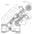
- FIG. 1 shows one exemplary application of the invention. That in the illustration Valve shown in longitudinal section can be, for example Line valve for water fittings, which one according to the invention by means of a handwheel 10 axially displaceable valve spindle 15 actuated.
- the valve stem 15 has at its end a closure piece 16, which guided axially displaceably within the valve housing 14 is and is moved against a valve seat 17.
- Figure 1 shows in the left half of the drawing the valve with the Closure piece 16 in an open position while in the right half of the drawing, the closure piece 16 in the closed position in which it can be seen rests on the valve seat 17 and the flow path for a Fluid blocked by the valve body.
- the valve has one Housing body with an inlet connector 22 and Output connector 23, which is axially connected to the input connector 22 is aligned, the valve seat 17 in the flow direction is arranged between these two. In a great Angle goes from the inlet port 22 of the housing part 14, the receives an upper part 13, which in the housing part 14 is rotatably and immovably.
- This upper part 13 shows, as can be seen in FIG. 1 an external thread 20 at its end facing away from the valve seat 17 on which an internal thread 11 of the handwheel 10 is screwed on.
- the section adjoining the outside has the handwheel 10 also a second internal thread 12, in which a Spindle head 18 of an axially displaceable valve spindle 15, which has a corresponding external thread 19, is screwed in.
- the internal thread 11 of the handwheel 10 and have the second internal thread 12 of the handwheel different sense of rotation, d. that is, one is a Left-hand thread and the other a right-hand thread or vice versa.
Landscapes
- Engineering & Computer Science (AREA)
- General Engineering & Computer Science (AREA)
- Mechanical Engineering (AREA)
- Mechanically-Actuated Valves (AREA)
- Measuring Pulse, Heart Rate, Blood Pressure Or Blood Flow (AREA)
- Magnetic Heads (AREA)
- Piezo-Electric Or Mechanical Vibrators, Or Delay Or Filter Circuits (AREA)
Applications Claiming Priority (2)
| Application Number | Priority Date | Filing Date | Title |
|---|---|---|---|
| DE10208540A DE10208540A1 (de) | 2002-02-27 | 2002-02-27 | Armatur mit Verstellorgan |
| DE10208540 | 2002-02-27 |
Publications (2)
| Publication Number | Publication Date |
|---|---|
| EP1340932A1 true EP1340932A1 (fr) | 2003-09-03 |
| EP1340932B1 EP1340932B1 (fr) | 2005-02-23 |
Family
ID=27675077
Family Applications (1)
| Application Number | Title | Priority Date | Filing Date |
|---|---|---|---|
| EP02027447A Expired - Lifetime EP1340932B1 (fr) | 2002-02-27 | 2002-12-10 | Armature avec organe de réglage |
Country Status (3)
| Country | Link |
|---|---|
| EP (1) | EP1340932B1 (fr) |
| AT (1) | ATE289664T1 (fr) |
| DE (2) | DE10208540A1 (fr) |
Citations (4)
| Publication number | Priority date | Publication date | Assignee | Title |
|---|---|---|---|---|
| GB742579A (en) * | 1952-05-29 | 1955-12-30 | Sydney Smith & Sons Nottingham | Improvements in fluid valves |
| GB2140533A (en) * | 1983-03-01 | 1984-11-28 | Douglas Diepa Williams | Precision valve |
| EP0134866A2 (fr) * | 1983-07-18 | 1985-03-27 | Kerotest Manufacturing Corporation | Soupape de commande |
| FR2665745A3 (fr) * | 1990-08-10 | 1992-02-14 | Transfluid Sa | Dispositif d'actionnement des moyens d'obturation d'une vanne a deplacement axial. |
Family Cites Families (4)
| Publication number | Priority date | Publication date | Assignee | Title |
|---|---|---|---|---|
| US1305182A (en) * | 1919-05-27 | Charles f | ||
| CH56005A (de) * | 1911-04-05 | 1912-10-01 | W & R Goebel | Anhebevorrichtung an Ventilen, mit einer ein Rechts- und ein Linksgewinde tragenden Spindel |
| GB323126A (en) * | 1929-01-09 | 1929-12-24 | Newman Hender And Company Ltd | Improvements in, and relating to, valves |
| GB367489A (en) * | 1930-12-09 | 1932-02-25 | Harold Lyall Mason | Improvements in valves, taps and the like |
-
2002
- 2002-02-27 DE DE10208540A patent/DE10208540A1/de not_active Ceased
- 2002-12-10 DE DE50202311T patent/DE50202311D1/de not_active Expired - Fee Related
- 2002-12-10 AT AT02027447T patent/ATE289664T1/de not_active IP Right Cessation
- 2002-12-10 EP EP02027447A patent/EP1340932B1/fr not_active Expired - Lifetime
Patent Citations (4)
| Publication number | Priority date | Publication date | Assignee | Title |
|---|---|---|---|---|
| GB742579A (en) * | 1952-05-29 | 1955-12-30 | Sydney Smith & Sons Nottingham | Improvements in fluid valves |
| GB2140533A (en) * | 1983-03-01 | 1984-11-28 | Douglas Diepa Williams | Precision valve |
| EP0134866A2 (fr) * | 1983-07-18 | 1985-03-27 | Kerotest Manufacturing Corporation | Soupape de commande |
| FR2665745A3 (fr) * | 1990-08-10 | 1992-02-14 | Transfluid Sa | Dispositif d'actionnement des moyens d'obturation d'une vanne a deplacement axial. |
Also Published As
| Publication number | Publication date |
|---|---|
| DE50202311D1 (de) | 2005-03-31 |
| DE10208540A1 (de) | 2003-09-11 |
| EP1340932B1 (fr) | 2005-02-23 |
| ATE289664T1 (de) | 2005-03-15 |
Similar Documents
| Publication | Publication Date | Title |
|---|---|---|
| DE102012109756B4 (de) | Steigendes Handventil mit Hubbegrenzung | |
| EP2226697B1 (fr) | Régulateur de débit | |
| EP2162590A1 (fr) | Soupape de régulation | |
| EP0061415A1 (fr) | Soupape pour systèmes hydrauliques | |
| DE3814248C2 (de) | Einstellbares Drosselrückschlagventil | |
| WO2008113462A1 (fr) | Soupape de réglage | |
| DE69004909T2 (de) | Mischventil mit Kugelhahn. | |
| DE2944520A1 (de) | Ventiloberteil | |
| DE4407447C2 (de) | Voreinstellbares Regulierventil | |
| EP1340932B1 (fr) | Armature avec organe de réglage | |
| DE102005017618B4 (de) | Ventil, insbesondere zum kontrollierten Abgeben von sich in einem Dampfkessel ansammelnden Salzen und dergleichen | |
| EP3217103B1 (fr) | Corps de soupape pour une soupape de corps chauffant et corps chauffant comprenant une soupape de corps chauffant | |
| DE8029630U1 (de) | Armatur zur fernbetaetigung des ablaufventils eines spueltisches | |
| EP3450776A1 (fr) | Appareil de réglage pour installations techniques | |
| EP0164438B1 (fr) | Clapet hydraulique | |
| DE69205974T2 (de) | Vorrichtung zum abwechselnden steuern von zwei zusammenwirkenden ventilen, insbesondere von sicherheitsventilen an druckkesseln. | |
| EP0071066B1 (fr) | Vanne de control de débit | |
| DE2904810C2 (de) | Drei- oder Mehrwegventil | |
| DE3208359A1 (de) | Ventil zur steuerung hydraulischer systeme | |
| DE202022001985U1 (de) | Regulierungsvorrichtung zur Durchflussregulierung eines Wasserdurchflusses | |
| EP4614035A1 (fr) | Soupape à piston annulaire | |
| EP4614034A1 (fr) | Soupape à piston annulaire | |
| DE60224029T2 (de) | Wasserhahn mit dem Auslass im Gehäuseoberteil | |
| DE4423856C2 (de) | Mischventil mit einem Zusatzgerät | |
| DE139081C (fr) |
Legal Events
| Date | Code | Title | Description |
|---|---|---|---|
| PUAI | Public reference made under article 153(3) epc to a published international application that has entered the european phase |
Free format text: ORIGINAL CODE: 0009012 |
|
| AK | Designated contracting states |
Kind code of ref document: A1 Designated state(s): AT BE BG CH CY CZ DE DK EE ES FI FR GB GR IE IT LI LU MC NL PT SE SI SK TR |
|
| AX | Request for extension of the european patent |
Extension state: AL LT LV MK RO |
|
| 17P | Request for examination filed |
Effective date: 20030814 |
|
| 17Q | First examination report despatched |
Effective date: 20040209 |
|
| AKX | Designation fees paid |
Designated state(s): AT BE BG CH CY CZ DE DK EE ES FI FR GB GR IE IT LI LU MC NL PT SE SI SK TR |
|
| GRAP | Despatch of communication of intention to grant a patent |
Free format text: ORIGINAL CODE: EPIDOSNIGR1 |
|
| RAP1 | Party data changed (applicant data changed or rights of an application transferred) |
Owner name: HONEYWELL TECHNOLOGIES SARL |
|
| GRAS | Grant fee paid |
Free format text: ORIGINAL CODE: EPIDOSNIGR3 |
|
| GRAA | (expected) grant |
Free format text: ORIGINAL CODE: 0009210 |
|
| AK | Designated contracting states |
Kind code of ref document: B1 Designated state(s): AT BE BG CH CY CZ DE DK EE ES FI FR GB GR IE IT LI LU MC NL PT SE SI SK TR |
|
| PG25 | Lapsed in a contracting state [announced via postgrant information from national office to epo] |
Ref country code: TR Free format text: LAPSE BECAUSE OF FAILURE TO SUBMIT A TRANSLATION OF THE DESCRIPTION OR TO PAY THE FEE WITHIN THE PRESCRIBED TIME-LIMIT Effective date: 20050223 Ref country code: SK Free format text: LAPSE BECAUSE OF FAILURE TO SUBMIT A TRANSLATION OF THE DESCRIPTION OR TO PAY THE FEE WITHIN THE PRESCRIBED TIME-LIMIT Effective date: 20050223 Ref country code: SI Free format text: LAPSE BECAUSE OF FAILURE TO SUBMIT A TRANSLATION OF THE DESCRIPTION OR TO PAY THE FEE WITHIN THE PRESCRIBED TIME-LIMIT Effective date: 20050223 Ref country code: NL Free format text: LAPSE BECAUSE OF FAILURE TO SUBMIT A TRANSLATION OF THE DESCRIPTION OR TO PAY THE FEE WITHIN THE PRESCRIBED TIME-LIMIT Effective date: 20050223 Ref country code: IT Free format text: LAPSE BECAUSE OF FAILURE TO SUBMIT A TRANSLATION OF THE DESCRIPTION OR TO PAY THE FEE WITHIN THE PRESCRIBED TIME-LIMIT;WARNING: LAPSES OF ITALIAN PATENTS WITH EFFECTIVE DATE BEFORE 2007 MAY HAVE OCCURRED AT ANY TIME BEFORE 2007. THE CORRECT EFFECTIVE DATE MAY BE DIFFERENT FROM THE ONE RECORDED. Effective date: 20050223 Ref country code: IE Free format text: LAPSE BECAUSE OF FAILURE TO SUBMIT A TRANSLATION OF THE DESCRIPTION OR TO PAY THE FEE WITHIN THE PRESCRIBED TIME-LIMIT Effective date: 20050223 Ref country code: GB Free format text: LAPSE BECAUSE OF FAILURE TO SUBMIT A TRANSLATION OF THE DESCRIPTION OR TO PAY THE FEE WITHIN THE PRESCRIBED TIME-LIMIT Effective date: 20050223 Ref country code: FR Free format text: LAPSE BECAUSE OF NON-PAYMENT OF DUE FEES Effective date: 20050223 Ref country code: FI Free format text: LAPSE BECAUSE OF FAILURE TO SUBMIT A TRANSLATION OF THE DESCRIPTION OR TO PAY THE FEE WITHIN THE PRESCRIBED TIME-LIMIT Effective date: 20050223 Ref country code: EE Free format text: LAPSE BECAUSE OF FAILURE TO SUBMIT A TRANSLATION OF THE DESCRIPTION OR TO PAY THE FEE WITHIN THE PRESCRIBED TIME-LIMIT Effective date: 20050223 Ref country code: CZ Free format text: LAPSE BECAUSE OF FAILURE TO SUBMIT A TRANSLATION OF THE DESCRIPTION OR TO PAY THE FEE WITHIN THE PRESCRIBED TIME-LIMIT Effective date: 20050223 Ref country code: BG Free format text: LAPSE BECAUSE OF FAILURE TO SUBMIT A TRANSLATION OF THE DESCRIPTION OR TO PAY THE FEE WITHIN THE PRESCRIBED TIME-LIMIT Effective date: 20050223 |
|
| REG | Reference to a national code |
Ref country code: GB Ref legal event code: FG4D Free format text: NOT ENGLISH |
|
| REG | Reference to a national code |
Ref country code: CH Ref legal event code: EP |
|
| REG | Reference to a national code |
Ref country code: IE Ref legal event code: FG4D Free format text: GERMAN |
|
| REF | Corresponds to: |
Ref document number: 50202311 Country of ref document: DE Date of ref document: 20050331 Kind code of ref document: P |
|
| PG25 | Lapsed in a contracting state [announced via postgrant information from national office to epo] |
Ref country code: SE Free format text: LAPSE BECAUSE OF FAILURE TO SUBMIT A TRANSLATION OF THE DESCRIPTION OR TO PAY THE FEE WITHIN THE PRESCRIBED TIME-LIMIT Effective date: 20050523 Ref country code: GR Free format text: LAPSE BECAUSE OF FAILURE TO SUBMIT A TRANSLATION OF THE DESCRIPTION OR TO PAY THE FEE WITHIN THE PRESCRIBED TIME-LIMIT Effective date: 20050523 Ref country code: DK Free format text: LAPSE BECAUSE OF FAILURE TO SUBMIT A TRANSLATION OF THE DESCRIPTION OR TO PAY THE FEE WITHIN THE PRESCRIBED TIME-LIMIT Effective date: 20050523 |
|
| PG25 | Lapsed in a contracting state [announced via postgrant information from national office to epo] |
Ref country code: ES Free format text: LAPSE BECAUSE OF FAILURE TO SUBMIT A TRANSLATION OF THE DESCRIPTION OR TO PAY THE FEE WITHIN THE PRESCRIBED TIME-LIMIT Effective date: 20050603 |
|
| NLV1 | Nl: lapsed or annulled due to failure to fulfill the requirements of art. 29p and 29m of the patents act | ||
| PG25 | Lapsed in a contracting state [announced via postgrant information from national office to epo] |
Ref country code: PT Free format text: LAPSE BECAUSE OF FAILURE TO SUBMIT A TRANSLATION OF THE DESCRIPTION OR TO PAY THE FEE WITHIN THE PRESCRIBED TIME-LIMIT Effective date: 20050804 |
|
| GBV | Gb: ep patent (uk) treated as always having been void in accordance with gb section 77(7)/1977 [no translation filed] |
Effective date: 20050223 |
|
| REG | Reference to a national code |
Ref country code: IE Ref legal event code: FD4D |
|
| PG25 | Lapsed in a contracting state [announced via postgrant information from national office to epo] |
Ref country code: CY Free format text: LAPSE BECAUSE OF FAILURE TO SUBMIT A TRANSLATION OF THE DESCRIPTION OR TO PAY THE FEE WITHIN THE PRESCRIBED TIME-LIMIT Effective date: 20051210 |
|
| PLBE | No opposition filed within time limit |
Free format text: ORIGINAL CODE: 0009261 |
|
| STAA | Information on the status of an ep patent application or granted ep patent |
Free format text: STATUS: NO OPPOSITION FILED WITHIN TIME LIMIT |
|
| PG25 | Lapsed in a contracting state [announced via postgrant information from national office to epo] |
Ref country code: MC Free format text: LAPSE BECAUSE OF NON-PAYMENT OF DUE FEES Effective date: 20051231 Ref country code: LU Free format text: LAPSE BECAUSE OF NON-PAYMENT OF DUE FEES Effective date: 20051231 Ref country code: BE Free format text: LAPSE BECAUSE OF NON-PAYMENT OF DUE FEES Effective date: 20051231 |
|
| 26N | No opposition filed |
Effective date: 20051124 |
|
| EN | Fr: translation not filed | ||
| PGFP | Annual fee paid to national office [announced via postgrant information from national office to epo] |
Ref country code: CH Payment date: 20061026 Year of fee payment: 5 |
|
| PGFP | Annual fee paid to national office [announced via postgrant information from national office to epo] |
Ref country code: AT Payment date: 20061107 Year of fee payment: 5 |
|
| PGFP | Annual fee paid to national office [announced via postgrant information from national office to epo] |
Ref country code: DE Payment date: 20061229 Year of fee payment: 5 |
|
| BERE | Be: lapsed |
Owner name: HONEYWELL TECHNOLOGIES SARL Effective date: 20051231 |
|
| REG | Reference to a national code |
Ref country code: CH Ref legal event code: PL |
|
| PG25 | Lapsed in a contracting state [announced via postgrant information from national office to epo] |
Ref country code: AT Free format text: LAPSE BECAUSE OF NON-PAYMENT OF DUE FEES Effective date: 20071210 |
|
| PG25 | Lapsed in a contracting state [announced via postgrant information from national office to epo] |
Ref country code: LI Free format text: LAPSE BECAUSE OF NON-PAYMENT OF DUE FEES Effective date: 20071231 Ref country code: DE Free format text: LAPSE BECAUSE OF NON-PAYMENT OF DUE FEES Effective date: 20080701 Ref country code: CH Free format text: LAPSE BECAUSE OF NON-PAYMENT OF DUE FEES Effective date: 20071231 |