EP1340965A1 - Méthodes et dispositif de mesure du contenu de réservoirs de liquide et du débit de liquides distribués de réservoirs et systèmes de contrôle de stock basés dessus - Google Patents
Méthodes et dispositif de mesure du contenu de réservoirs de liquide et du débit de liquides distribués de réservoirs et systèmes de contrôle de stock basés dessus Download PDFInfo
- Publication number
- EP1340965A1 EP1340965A1 EP02251475A EP02251475A EP1340965A1 EP 1340965 A1 EP1340965 A1 EP 1340965A1 EP 02251475 A EP02251475 A EP 02251475A EP 02251475 A EP02251475 A EP 02251475A EP 1340965 A1 EP1340965 A1 EP 1340965A1
- Authority
- EP
- European Patent Office
- Prior art keywords
- liquid
- pressure
- volume
- vessel
- fluid path
- Prior art date
- Legal status (The legal status is an assumption and is not a legal conclusion. Google has not performed a legal analysis and makes no representation as to the accuracy of the status listed.)
- Withdrawn
Links
- 239000007788 liquid Substances 0.000 title claims abstract description 130
- 238000000034 method Methods 0.000 title claims abstract description 25
- 239000012530 fluid Substances 0.000 claims abstract description 53
- 238000010079 rubber tapping Methods 0.000 claims abstract description 25
- 238000012544 monitoring process Methods 0.000 claims abstract description 18
- 238000012545 processing Methods 0.000 claims description 17
- 238000005259 measurement Methods 0.000 claims description 10
- 230000010354 integration Effects 0.000 claims description 6
- 230000008569 process Effects 0.000 claims description 4
- 235000013405 beer Nutrition 0.000 abstract description 32
- 239000007789 gas Substances 0.000 description 11
- 230000000903 blocking effect Effects 0.000 description 5
- CURLTUGMZLYLDI-UHFFFAOYSA-N Carbon dioxide Chemical compound O=C=O CURLTUGMZLYLDI-UHFFFAOYSA-N 0.000 description 4
- IJGRMHOSHXDMSA-UHFFFAOYSA-N Atomic nitrogen Chemical compound N#N IJGRMHOSHXDMSA-UHFFFAOYSA-N 0.000 description 2
- 229910002092 carbon dioxide Inorganic materials 0.000 description 2
- 239000001569 carbon dioxide Substances 0.000 description 2
- 238000004891 communication Methods 0.000 description 2
- 238000010586 diagram Methods 0.000 description 2
- 238000012384 transportation and delivery Methods 0.000 description 2
- 238000011144 upstream manufacturing Methods 0.000 description 2
- 230000002596 correlated effect Effects 0.000 description 1
- 239000000446 fuel Substances 0.000 description 1
- 239000011521 glass Substances 0.000 description 1
- 239000000203 mixture Substances 0.000 description 1
- 238000012986 modification Methods 0.000 description 1
- 230000004048 modification Effects 0.000 description 1
- 229910052757 nitrogen Inorganic materials 0.000 description 1
- 239000000126 substance Substances 0.000 description 1
- 238000005303 weighing Methods 0.000 description 1
Images

Classifications
-
- G—PHYSICS
- G01—MEASURING; TESTING
- G01F—MEASURING VOLUME, VOLUME FLOW, MASS FLOW OR LIQUID LEVEL; METERING BY VOLUME
- G01F22/00—Methods or apparatus for measuring volume of fluids or fluent solid material, not otherwise provided for
- G01F22/02—Methods or apparatus for measuring volume of fluids or fluent solid material, not otherwise provided for involving measurement of pressure
-
- G—PHYSICS
- G01—MEASURING; TESTING
- G01F—MEASURING VOLUME, VOLUME FLOW, MASS FLOW OR LIQUID LEVEL; METERING BY VOLUME
- G01F1/00—Measuring the volume flow or mass flow of fluid or fluent solid material wherein the fluid passes through a meter in a continuous flow
- G01F1/05—Measuring the volume flow or mass flow of fluid or fluent solid material wherein the fluid passes through a meter in a continuous flow by using mechanical effects
- G01F1/34—Measuring the volume flow or mass flow of fluid or fluent solid material wherein the fluid passes through a meter in a continuous flow by using mechanical effects by measuring pressure or differential pressure
-
- G—PHYSICS
- G01—MEASURING; TESTING
- G01F—MEASURING VOLUME, VOLUME FLOW, MASS FLOW OR LIQUID LEVEL; METERING BY VOLUME
- G01F23/00—Indicating or measuring liquid level or level of fluent solid material, e.g. indicating in terms of volume or indicating by means of an alarm
- G01F23/14—Indicating or measuring liquid level or level of fluent solid material, e.g. indicating in terms of volume or indicating by means of an alarm by measurement of pressure
-
- G—PHYSICS
- G01—MEASURING; TESTING
- G01F—MEASURING VOLUME, VOLUME FLOW, MASS FLOW OR LIQUID LEVEL; METERING BY VOLUME
- G01F23/00—Indicating or measuring liquid level or level of fluent solid material, e.g. indicating in terms of volume or indicating by means of an alarm
- G01F23/14—Indicating or measuring liquid level or level of fluent solid material, e.g. indicating in terms of volume or indicating by means of an alarm by measurement of pressure
- G01F23/16—Indicating, recording, or alarm devices being actuated by mechanical or fluid means, e.g. using gas, mercury, or a diaphragm as transmitting element, or by a column of liquid
- G01F23/162—Indicating, recording, or alarm devices being actuated by mechanical or fluid means, e.g. using gas, mercury, or a diaphragm as transmitting element, or by a column of liquid by a liquid column
Definitions
- the invention relates to methods and apparatus for measuring the quantity of liquid contained in a container of the type in which liquid is dispensed from the container by being drawn off through a conduit extending downwardly into the liquid from a point above the level of the surface of the liquid (i.e. the liquid is drawn off through the conduit by a difference in the pressure in the container above the liquid and the pressure in the conduit), and/or for measuring the flow rate of liquids dispensed from such containers.
- the invention is particularly applicable to beer kegs or the like, liquid storage tanks including underground storage tanks, liquid storage drums, etc.
- the invention further relates to stock monitoring and control systems based on such methods and apparatus.
- a method of measuring the volume of liquid contained in a vessel of the type in which liquid is dispensed from the vessel via a fluid path having an open lower end submerged in the liquid and an upper end extending out of the container above the level of said liquid by means of a pressure difference DP between a pressure P2 in the vessel above the liquid and a pressure P1 at a predetermined point in said fluid path comprising the steps of determining the pressure difference DP, and determining the volume of said liquid from said pressure difference DP.
- the step of determining the volume of said liquid from said pressure difference DP comprises determining the height H between the surface of said liquid and said predetermined point in said fluid path, determining the depth D of said liquid from said height H, and determining the volume of said liquid from said depth D.
- a method of monitoring the volume of liquid contained in and the volume of liquid dispensed from a vessel of the type in which liquid is dispensed from the vessel via a fluid path having an open lower end submerged in the liquid and an upper end extending out of the container above the level of said liquid by means of a pressure difference DP between a pressure P2 in the vessel above the liquid and a pressure P1 at a predetermined point in said fluid path, comprising the steps of:
- the vessel is closed and the head space in the vessel above the liquid level is pressurised, the liquid being driven along the fluid path by the elevated pressure P2 in the head space.
- the pressure difference DP is measured by means of a differential pressure transducer having a first side adapted to communicate with said fluid path and a second side adapted to communicate with the interior of said vessel above the level of said liquid.
- the interior of the vessel is at atmospheric pressure and the liquid is drawn through the fluid path by a reduced pressure downstream in the fluid path.
- the pressure difference DP may be measured by measuring the gauge pressure in the fluid path.
- apparatus for performing a method in accordance with the first and/or second and/or third aspects of the invention comprising pressure sensing means adapted for determining said pressure difference DP.
- said pressure sensing means comprises a differential pressure transducer having a first side adapted to communicate with said fluid path and a second side adapted to communicate with the interior of said vessel above the level of said liquid.
- said pressure sensing means may comprise a gauge pressure sensor arranged to measure the gauge pressure in the fluid path.
- the apparatus further includes data processing means adapted to receive pressure data defining said pressure difference DP and to calculate at least one of said liquid volume, said liquid flow rate and said dispensed liquid volume therefrom.
- said data processing means includes a store of vessel data whereby said liquid volume and/or said flow rate may be calculated from said pressure data.
- said data processing means is further adapted to perform time integration of flow rate data in order to determine a volume of liquid dispensed from said vessel.
- a stock monitoring system for monitoring the contents of at least one liquid vessel using the methods and/or apparatus in accordance with at least one of the first, second, third and fourth aspects of the invention.
- a tapping head for a pressurised liquid container, said tapping head having a first fluid conduit for forming part of a fluid dispense path for dispensing liquid from said container and a second fluid conduit for injecting pressurised gas into said container, a first pressure sensing port communicating with said first conduit and a second pressure sensing port communicating with said second conduit.
- the tapping head may include at least one pressure sensor for generating signals representing either: (a) the pressure at said first pressure sensing port and the pressure at said second sensing port; or (b) the difference between the pressure at said first pressure sensing port and the pressure at said second sensing port.
- the tapping head includes a pressure gauge communicating with said first and second pressure sensing ports for measuring the difference between the pressure at said first pressure sensing port and the pressure at said second sensing port, and having a display calibrated to display the volume of the container contents as a function of said pressure difference.
- data processing apparatus adapted to receive pressure data and to determine liquid volumes and/or flow rates therefrom in accordance with at least one of the first, second and third aspects of the invention.
- a portable data logging device adapted to receive pressure data obtained in accordance with the method of the first aspect of the invention and further adapted for receiving data for determining the contents of partially used bottles.
- the device may include a distance measuring device for measuring the depth of the contents of said bottles or a weight measuring device for measuring the weight of said bottles, and a barcode reader for reading barcodes from said bottles, and may be adapted to process said pressure data in order to determine the volume of the contents of a container in accordance with the first aspect of the invention and to correlate said depth or weight measurements with said barcodes so as to derive the current volume of the bottle contents using a store of data relating the depth of the contents or the weight of the bottle to volume for a variety of known types of bottle identified by their barcodes.
- the invention will first be described by reference to embodiments thereof specifically concerned with measuring the contents of pressurised beer kegs. However, it will be understood that the invention is of wider application for measuring the contents of and flow rates from other types of liquid containers, as shall be described further below.
- FIG. 1 there is shown an example of a typical pressurised beer keg 10 containing a volume of beer 12.
- a tubular fluid conduit 14 known as a spear tube extends upwards from a free end 16 at a point close to the bottom of the interior volume of the keg 10 and has an upper end 18 connected to a tapping head 20 installed on the outlet of the keg 10. Via the tapping head 20, the spear tube 14 communicates with a beer line 22, which extends to a dispense point, typically a beer tap (“dispense valve”) installed on a bar.
- the spear tube 14 and beer line 22 together constitute a dispense path from the keg to the dispense valve.
- a head space 24 above the volume of beer 12 contains pressurised gas (the "driving gas", normally carbon dioxide or a mixture of carbon dioxide and nitrogen).
- the head space 24 is connected to a source of pressurised gas via a fluid passage 26 extending through the tapping head 20 and a gas line 28.
- the pressure in the head space 24 drives the beer out of the keg 10 through the spear tube 14 when the dispense valve is opened.
- the present invention involves measuring the difference DP between the pressure P1 in the dispense path and the pressure P2 in the head space 24.
- this provides the basis for determining the depth D of the beer 12 in order to determine the volume of beer in the keg.
- DP varies substantially linearly with the height H above the surface of the beer volume 12 at which the pressure P1 is measured. Given knowledge of the relevant dimensions of the keg 10, or prior calibration, the depth D can thus be deduced and hence the volume V of the beer 24 contained in the keg 10, based on the pressure difference DP. For an accurate result, this requires substantially zero flow conditions in the dispense path and in the gas line 28.
- DP can be used to determine the rate of flow Q through the spear tube 14.
- the flow rate Q varies with the difference between the value of DP while the beer is flowing, DP2, and the value of DP under zero flow conditions, DP1, divided by the effective path length between the two points at which the pressure is measured, H in this example; i.e.: Q ⁇ (DP2 - DP1) /H
- Such a discontinuity may be deliberately included in the dispense path for the purposes of the present invention, or may exist in any case; e.g. as a result of a connection between two dissimilar conduits adjacent the P1 sensing point.
- time integration of measured flow rates allows the volume of beer dispensed from the keg 10 to be monitored.
- the pressure P1 can be sensed at any suitable point in the dispense path provided that there are no one-way valves or the like between the pressure sensing point and the keg 10 which could affect the measured pressure.
- the pressure P2 can be sensed at any point in the keg 10, tapping head 20 or gas line 28 where the pressure is equal to the pressure in the head space 24. Again, there should be no one-way valves or the like between the pressure sensing point and the head space 24.
- P1 is measured at a point in a fluid passage 30 extending through the tapping head 20 and interconnecting the spear tube 14 and the beer line 22 and P2 is measured in a spigot 32 connecting the fluid passage 26 in the tapping head 20 to the gas line 28.
- Blocking valves 34 and 36 are fitted to the tapping head 20 and spigot 32 at the pressure sensing points, whereby pressure sensing means 38 may be removably connected to the pressure sensing points.
- the pressure difference DP may be determined by means of any type of pressure sensors suited for measuring the relevant liquid and gas pressures P1 and P2.
- the pressures P1 and P2 could be measured independently and the value of DP calculated from the values of P1 and P2.
- DP is measured by means of a differential pressure transducer 38 having one side connected to the P1 sensing point (in this embodiment, via a first conduit 40 and the first blocking valve 34) and its other side connected to the P2 sensing point (in this embodiment, via a second conduit 42 and the second blocking valve 36).
- tapping head having the blocking valves 34 and 36 fitted thereto in communication with the fluid passages 30 and 20, enabling the pressure sensing means 38 to be temporarily connected to the valves 34, 36 when required.
- pressure sensing means could be permanently installed in the tapping head, in which case the blocking valves 34, 36 are not required.
- Tapping heads may be purpose-made for the present invention or existing tapping heads may be modified for the purposes of the invention.
- the pressure sensing points for P1 and P2 may be provided in pipe pieces which may be screwed into the tapping head and which are suitably machined to house one-way valves which are normally included in the beer port and gas line of a conventional tapping head (as noted above, the pressure sensing points would be located between the one-way valves and the keg).
- the volume of the beer 12 contained in the keg and/or the flow rate of beer through the dispense path can be determined as explained above.
- the value of DP must be sufficient to drive the liquid in the keg 10 to the P1 pressure sensing point.
- the pressure data output from the pressure sensing means may be transmitted to any suitable type of data processing system in order to determine the volume of beer 12 and/or flow rate Q, via any suitable cabled or wireless connection.
- the data processing system to which the pressure data is transmitted includes container data (or "vessel data") relating to the specific keg type, either in the form of data describing the configuration of the keg, including the height H, or previously obtained calibration data, suitably in the form of a look-up table, from which the height D and hence the volume of beer may be calculated, and/or from which the flow rate Q may be calculated.
- the system will include container data for each keg type and some means will also be required to identify the type of keg to which particular pressure data relates. This may be done in a variety of ways, either automatically or by means of manual user input.
- the pressure data output from the pressure sensing means 38 is input to a portable (preferably hand-held) electronic data logging unit 44, typically having a display 46, keypad or the like 48 and output port 50, and including the relevant container data.
- the unit is adapted to calculate, log and display the volume and/or flow rate calculated from the pressure data. If required, these may be transmitted via the output port 50, via any suitable cabled or wireless connection, to a further data processing system or network, as shall be described further below.
- the invention may be used simply to provide measurements of liquid volumes and/or flow rates, which can be used locally for stock monitoring/control purposes.
- the invention may provide the basis for, or be integrated into, a more sophisticated stock/monitoring system, either locally or on a wide area basis.
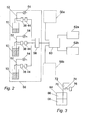
- FIG. 2 shows a plurality of kegs 10, each having a dispense path 52 to a dispense valve 54, and each having pressure sensing means 38 and local data logging unit 44 as described in relation to Fig. 1, all located in a public house or other licensed premises or the like, indicated by broken line 56.
- Each of the kegs 10 would have a gas line 28 as in Fig. 1. These have been omitted from Fig. 2 for simplicity.
- a local data network connects the units 44 to a local host data processing system 58. It will be understood that a system of this type could be arranged in a number of ways.
- a pressure sensing means 38 and unit 44 could be connected temporarily to each keg as and when required and collected data downloaded to the local host 58.
- each keg or tapping head associated with a keg
- each keg could be permanently fitted with pressure sensing means 38 and a unit 44, or the pressure sensing means could communicate directly with the local host 58, which would take over the functionality of the units 44.
- the host 58 receives and processes information which allows monitoring of the volume of liquid in the kegs 10 and/or, from the flow rate Q, the volume of liquid dispensed from the kegs 10, together with deliveries of new stock.
- This information provides the basis for sophisticated stock control functions; for example, facilitating and optimising the re-ordering of stock from an external supplier, and reconciling remaining stock with quantities dispensed and sales records.
- the system described thus far may operate as a local stand-alone system.
- a local system of this type could be connected to a wide area networked system serving a number of different premises such as 56a, 56b, each having a local system similar to that described above.
- the local host 58 of each or the premises 56, 56a, 56b may be connected by any suitable wide area network channels to a network host 60, providing a central stock monitoring/control system for any number of different premises.
- the processing of the pressure data may be performed locally or centrally. In the latter case, the local host 58 may serve simply as a communications interface between the pressure sensing means 38 and the network host 60.
- the network may be extended to communicate directly with a number of suppliers such as 62a and 62b, further automating or streamlining the ordering and delivery of new stock (alternatively, local hosts 58 could communicate directly with suppliers 62a, 62b without an intermediate network host 60).
- the ability to measure the flow rate from the kegs 10 also provides the basis for automatic control of beer dispense, particularly when combined with a load cell measurement system at the point of dispense for determining the volume of beer dispensed into a glass, such as is described in copending British Patent Applications Nos. 9920822.5 and 0001497.7.
- the invention has been described thus far specifically in relation to pressurised beer kegs in a licensed trade environment.
- the invention is also applicable to other types of liquid containers from which liquid is dispensed via a conduit extending downwards into the liquid from a point above the liquid level.
- This includes other types of container in which liquid is dispensed through the conduit by an elevated pressure in the head space above the liquid in the container, and types of container in which liquid is dispensed by means of a pressure difference DP generated by other means, such as a vacuum pump in the dispense path.
- a pressure difference DP generated by other means, such as a vacuum pump in the dispense path.
- the pressure difference DP may be measured simply by measuring the gauge pressure in the fluid path 70, upstream of the pump 72, using a gauge pressure sensor 74 which has an output connected to any suitable data processing means 76.
- Such other types of containers include underground fuel storage tanks in petrol stations and drums for storing any of a variety of liquid chemical products.
- Various arrangements for local and remote data processing and related systems may be applied in such cases in a similar manner to those described in relation to Figs. 1 and 2 for beer kegs.
- the invention also allows the checking of the volume of full containers provided that liquid is bled through the conduit/dispense path to a point higher than the P1 pressure sensing point.
- the data processing means such as 44 and/or 58 and/or 60 which interprets the pressure data from the pressure sensing means may be connected to any suitable type of alarm, indicator or automatic container changeover system. This allows empty containers to be swapped for fresh, full containers in a controlled and better managed manner.
- the measurement instrumentation required by the present invention has no moving parts and provides results without the need to untap and retap the keg or other container.
- a differential pressure transducer is used as the pressure sensing means, this is preferably located close to and with a fixed relative orientation to the P1 pressure sensing point in the dispense path.
- the pressure sensing means is preferably suited for wet operation, at least in relation to the higher pressure P2 sensing point.
- a sensor suited for dry operation may be used provided it is arranged that the higher pressure sensing point is higher than the P1 pressure sensing point so that a small air cushion is established between the sensor and the monitoring point.
Landscapes
- Physics & Mathematics (AREA)
- Fluid Mechanics (AREA)
- General Physics & Mathematics (AREA)
- Measurement Of Levels Of Liquids Or Fluent Solid Materials (AREA)
Priority Applications (4)
| Application Number | Priority Date | Filing Date | Title |
|---|---|---|---|
| GBGB0012175.6A GB0012175D0 (en) | 2000-05-20 | 2000-05-20 | Methods and apparatus for measuring the contents of liquid containers and the flow rate of liquids dispensed from liquid containers and stock control system |
| GB0112296A GB2367625A (en) | 2000-05-20 | 2001-05-21 | Methods and apparatus for measuring the contents of liquid containers and the flow rate of liquids dispensed from liquid containers |
| EP02251475A EP1340965A1 (fr) | 2000-05-20 | 2002-03-02 | Méthodes et dispositif de mesure du contenu de réservoirs de liquide et du débit de liquides distribués de réservoirs et systèmes de contrôle de stock basés dessus |
| US10/097,316 US20030172745A1 (en) | 2000-05-20 | 2002-03-14 | Methods and apparatus for measuring the contents of liquid containers and the flow rate of liquids dispensed from liquid containers and stock control systems based thereon |
Applications Claiming Priority (3)
| Application Number | Priority Date | Filing Date | Title |
|---|---|---|---|
| GBGB0012175.6A GB0012175D0 (en) | 2000-05-20 | 2000-05-20 | Methods and apparatus for measuring the contents of liquid containers and the flow rate of liquids dispensed from liquid containers and stock control system |
| EP02251475A EP1340965A1 (fr) | 2000-05-20 | 2002-03-02 | Méthodes et dispositif de mesure du contenu de réservoirs de liquide et du débit de liquides distribués de réservoirs et systèmes de contrôle de stock basés dessus |
| US10/097,316 US20030172745A1 (en) | 2000-05-20 | 2002-03-14 | Methods and apparatus for measuring the contents of liquid containers and the flow rate of liquids dispensed from liquid containers and stock control systems based thereon |
Publications (1)
| Publication Number | Publication Date |
|---|---|
| EP1340965A1 true EP1340965A1 (fr) | 2003-09-03 |
Family
ID=29721008
Family Applications (1)
| Application Number | Title | Priority Date | Filing Date |
|---|---|---|---|
| EP02251475A Withdrawn EP1340965A1 (fr) | 2000-05-20 | 2002-03-02 | Méthodes et dispositif de mesure du contenu de réservoirs de liquide et du débit de liquides distribués de réservoirs et systèmes de contrôle de stock basés dessus |
Country Status (3)
| Country | Link |
|---|---|
| US (1) | US20030172745A1 (fr) |
| EP (1) | EP1340965A1 (fr) |
| GB (2) | GB0012175D0 (fr) |
Cited By (1)
| Publication number | Priority date | Publication date | Assignee | Title |
|---|---|---|---|---|
| DE102007057832A1 (de) * | 2007-11-30 | 2009-06-04 | Niro-Plan Ag | Füllstandsmessvorrichtung und Verfahren zum Messen des Füllstandes eines flüssigen Lebensmittels in einem Behälter |
Families Citing this family (18)
| Publication number | Priority date | Publication date | Assignee | Title |
|---|---|---|---|---|
| GB0012175D0 (en) * | 2000-05-20 | 2000-07-12 | Linburn Tech Ltd | Methods and apparatus for measuring the contents of liquid containers and the flow rate of liquids dispensed from liquid containers and stock control system |
| US6766379B2 (en) * | 2002-09-03 | 2004-07-20 | Motorola, Inc. | Providing multiple unicast resource records to domain name servers for indication of simultaneously sending multiple unicast messages to different IP destinations that share a common domain name |
| US8366690B2 (en) * | 2006-09-19 | 2013-02-05 | Kci Licensing, Inc. | System and method for determining a fill status of a canister of fluid in a reduced pressure treatment system |
| US8874388B2 (en) * | 2009-09-15 | 2014-10-28 | On Site Gas Systems, Inc. | Method and system for measuring a rate of flow of an output |
| US8579859B2 (en) * | 2009-12-26 | 2013-11-12 | Board Of Regents, The University Of Texas System | Fluid balance monitoring system with fluid infusion pump for medical treatment |
| US8925382B1 (en) * | 2012-03-09 | 2015-01-06 | Kevin Beal | System and process for measuring a volume of a liquid within a keg |
| ITTO20120418A1 (it) * | 2012-05-09 | 2013-11-10 | Egro Suisse Ag | Dispositivo per misurare il livello del latte e relativo metodo di misura |
| US9221667B2 (en) | 2012-05-24 | 2015-12-29 | SteadyServ Technologies, LLC | Draft beer supply chain systems and methods |
| RU2505788C1 (ru) * | 2012-07-02 | 2014-01-27 | Федеральное государственное унитарное предприятие "Государственный космический научно-производственный центр имени М.В. Хруничева" | Способ измерения расхода жидкости |
| CA2929131C (fr) * | 2013-11-03 | 2023-11-07 | SteadyServ Technologies, LLC | Systemes et procedes pour circuit d'alimentation en biere pression |
| WO2016089389A1 (fr) * | 2014-12-03 | 2016-06-09 | Kevin Beal | Système et procédé de mesure d'un volume de liquide à l'intérieur d'un fût |
| US10745263B2 (en) | 2015-05-28 | 2020-08-18 | Sonicu, Llc | Container fill level indication system using a machine learning algorithm |
| US10746586B2 (en) | 2015-05-28 | 2020-08-18 | Sonicu, Llc | Tank-in-tank container fill level indicator |
| US10578475B2 (en) | 2016-04-29 | 2020-03-03 | Beverage Intel, Llc | Sensing devices and systems including examples of pairing sensing devices to containers |
| EP3376182A1 (fr) * | 2017-03-14 | 2018-09-19 | CSEM Centre Suisse D'electronique Et De Microtechnique SA | Système et procédé de distribution de fluide |
| CN107643076B (zh) * | 2017-09-28 | 2024-06-14 | 中国水利水电科学研究院 | 一种便携式湖库表层流场实时监测装置及其监测方法 |
| US11209300B2 (en) * | 2018-03-29 | 2021-12-28 | William Arthur Johnson | Fluid monitoring system and methods of use |
| FR3107352B1 (fr) * | 2020-02-17 | 2022-01-14 | Vitesco Technologies | Procédé de mesure d’un débit de liquide à la sortie d’une pompe |
Citations (8)
| Publication number | Priority date | Publication date | Assignee | Title |
|---|---|---|---|---|
| GB1223848A (en) * | 1967-10-10 | 1971-03-03 | Whitbread & Company Ltd | Improvements in the measurement of the volume of beer or like beverages in containers |
| GB1577499A (en) * | 1978-05-25 | 1980-10-22 | Distillers Co Yeast Ltd | Apparatus for determining the depth of beer in a keg |
| GB2077432A (en) * | 1980-06-04 | 1981-12-16 | Distillers Co Carbon Dioxide | Apparatus for determining the depth of beer in a keg |
| EP0414156A2 (fr) * | 1989-08-20 | 1991-02-27 | Control Technology, Inc. | Dispositif de distribution de boisson |
| GB2259147A (en) * | 1991-08-15 | 1993-03-03 | Burreng Limited | Pressure sensor |
| US5511694A (en) * | 1994-01-19 | 1996-04-30 | Rohm; Edward J. | Apparatus and article for determining and indicating liquid content of kegs or barrels |
| WO1998001726A1 (fr) * | 1996-07-08 | 1998-01-15 | William Gordon Willis | Dispositif et methode pour mesurer le contenu en fluide d'un conteneur |
| GB2367625A (en) * | 2000-05-20 | 2002-04-10 | Linburn Technology Ltd | Methods and apparatus for measuring the contents of liquid containers and the flow rate of liquids dispensed from liquid containers |
Family Cites Families (2)
| Publication number | Priority date | Publication date | Assignee | Title |
|---|---|---|---|---|
| GB8618276D0 (en) * | 1986-07-26 | 1986-09-03 | Bass Plc | Measuring level of beverage in keg |
| JPH02278126A (ja) * | 1989-04-20 | 1990-11-14 | Fuji Electric Co Ltd | 液位測定装置 |
-
2000
- 2000-05-20 GB GBGB0012175.6A patent/GB0012175D0/en not_active Ceased
-
2001
- 2001-05-21 GB GB0112296A patent/GB2367625A/en not_active Withdrawn
-
2002
- 2002-03-02 EP EP02251475A patent/EP1340965A1/fr not_active Withdrawn
- 2002-03-14 US US10/097,316 patent/US20030172745A1/en not_active Abandoned
Patent Citations (8)
| Publication number | Priority date | Publication date | Assignee | Title |
|---|---|---|---|---|
| GB1223848A (en) * | 1967-10-10 | 1971-03-03 | Whitbread & Company Ltd | Improvements in the measurement of the volume of beer or like beverages in containers |
| GB1577499A (en) * | 1978-05-25 | 1980-10-22 | Distillers Co Yeast Ltd | Apparatus for determining the depth of beer in a keg |
| GB2077432A (en) * | 1980-06-04 | 1981-12-16 | Distillers Co Carbon Dioxide | Apparatus for determining the depth of beer in a keg |
| EP0414156A2 (fr) * | 1989-08-20 | 1991-02-27 | Control Technology, Inc. | Dispositif de distribution de boisson |
| GB2259147A (en) * | 1991-08-15 | 1993-03-03 | Burreng Limited | Pressure sensor |
| US5511694A (en) * | 1994-01-19 | 1996-04-30 | Rohm; Edward J. | Apparatus and article for determining and indicating liquid content of kegs or barrels |
| WO1998001726A1 (fr) * | 1996-07-08 | 1998-01-15 | William Gordon Willis | Dispositif et methode pour mesurer le contenu en fluide d'un conteneur |
| GB2367625A (en) * | 2000-05-20 | 2002-04-10 | Linburn Technology Ltd | Methods and apparatus for measuring the contents of liquid containers and the flow rate of liquids dispensed from liquid containers |
Cited By (1)
| Publication number | Priority date | Publication date | Assignee | Title |
|---|---|---|---|---|
| DE102007057832A1 (de) * | 2007-11-30 | 2009-06-04 | Niro-Plan Ag | Füllstandsmessvorrichtung und Verfahren zum Messen des Füllstandes eines flüssigen Lebensmittels in einem Behälter |
Also Published As
| Publication number | Publication date |
|---|---|
| GB0012175D0 (en) | 2000-07-12 |
| GB0112296D0 (en) | 2001-07-11 |
| GB2367625A (en) | 2002-04-10 |
| US20030172745A1 (en) | 2003-09-18 |
Similar Documents
| Publication | Publication Date | Title |
|---|---|---|
| US20030172745A1 (en) | Methods and apparatus for measuring the contents of liquid containers and the flow rate of liquids dispensed from liquid containers and stock control systems based thereon | |
| US4147893A (en) | Gauging system providing remote readout of liquid levels in gasoline storage tanks | |
| US8925382B1 (en) | System and process for measuring a volume of a liquid within a keg | |
| EP1381832B1 (fr) | Procede d'estimation de precision des mesures d'un compteur de debit | |
| US20040045623A1 (en) | Method and apparatus for fluid transport, storage and dispensing | |
| US20110253746A1 (en) | Wine dispensing system | |
| EP2646738B1 (fr) | Distributeur de liquide | |
| CN110300723B (zh) | 带有燃油分析器的加油机 | |
| AU2018371404B2 (en) | Liquid sale management device | |
| US20150329346A1 (en) | Systems for monitoring and displaying information for beverage dispensing systems | |
| US20180100751A1 (en) | Temporal based measurement system providing real time tracking | |
| US20110011891A9 (en) | Method and device to measure the level of pressurized liquid in a siphon container | |
| FI106019B (fi) | Menetelmä ja laitteisto nesteen jakelussa panimoalueen eri käyttöpaikoissa oleviin nestesuursäiliöihin | |
| GB2415952A (en) | Liquid supply changeover system | |
| WO2016089389A1 (fr) | Système et procédé de mesure d'un volume de liquide à l'intérieur d'un fût | |
| JP2007309778A (ja) | 流量計およびガス流量計測システム | |
| CN113874685A (zh) | 获取关于储存流体的容器的填充水平的信息的设备和方法 | |
| US6950759B2 (en) | Apparatus and method for determining the amount of flow of a substance through a tube/pipe | |
| AU2007200878A1 (en) | Fluid transfer apparatus and method | |
| CN205035077U (zh) | 罐车原油交接动态计量系统 | |
| US20090013781A1 (en) | Method and device to measure the level of pressurized liquid in a siphon container | |
| EP1009978A1 (fr) | Dispositif et methode pour mesurer le contenu en fluide d'un conteneur | |
| JP2020070085A (ja) | 2つ以上の飲料タンクを備える炭酸飲料提供装置 | |
| CA3083088C (fr) | Dispositif de gestion de vente de liquide | |
| CN111566041B (zh) | 液体售卖管理系统 |
Legal Events
| Date | Code | Title | Description |
|---|---|---|---|
| PUAI | Public reference made under article 153(3) epc to a published international application that has entered the european phase |
Free format text: ORIGINAL CODE: 0009012 |
|
| AK | Designated contracting states |
Kind code of ref document: A1 Designated state(s): AT BE CH CY DE DK ES FI FR GB GR IE IT LI LU MC NL PT SE TR |
|
| AX | Request for extension of the european patent |
Extension state: AL LT LV MK RO SI |
|
| AKX | Designation fees paid | ||
| REG | Reference to a national code |
Ref country code: DE Ref legal event code: 8566 |
|
| STAA | Information on the status of an ep patent application or granted ep patent |
Free format text: STATUS: THE APPLICATION IS DEEMED TO BE WITHDRAWN |
|
| 18D | Application deemed to be withdrawn |
Effective date: 20040304 |