EP1341069A1 - Flow controller and valve with flow controller - Google Patents
Flow controller and valve with flow controller Download PDFInfo
- Publication number
- EP1341069A1 EP1341069A1 EP03002808A EP03002808A EP1341069A1 EP 1341069 A1 EP1341069 A1 EP 1341069A1 EP 03002808 A EP03002808 A EP 03002808A EP 03002808 A EP03002808 A EP 03002808A EP 1341069 A1 EP1341069 A1 EP 1341069A1
- Authority
- EP
- European Patent Office
- Prior art keywords
- control element
- flow controller
- flow
- valve
- section
- Prior art date
- Legal status (The legal status is an assumption and is not a legal conclusion. Google has not performed a legal analysis and makes no representation as to the accuracy of the status listed.)
- Granted
Links
Images


Classifications
-
- G—PHYSICS
- G05—CONTROLLING; REGULATING
- G05D—SYSTEMS FOR CONTROLLING OR REGULATING NON-ELECTRIC VARIABLES
- G05D7/00—Control of flow
- G05D7/01—Control of flow without auxiliary power
- G05D7/0126—Control of flow without auxiliary power the sensing element being a piston or plunger associated with one or more springs
- G05D7/0133—Control of flow without auxiliary power the sensing element being a piston or plunger associated with one or more springs within the flow-path
Definitions
- the present invention relates to a flow controller a fixed jacket part, which is essentially in axial A fluid flows through the direction and within the Shell part axially displaceable control element against a spring force, where the cross section of flow openings through the Flow controller depending on the respective position of the Control element varies.
- the invention further relates to a Thermostatic valve, in the housing of which there is a flow regulator aforementioned type is used.
- Flow regulators of the type mentioned at the outset are state of the art known in the art.
- the DE 2 258 787 A1 a flow controller in which in the peripheral area various holes are provided in the control element, whereas the inside cross section of the jacket part, within it the control element shifts in the axial direction, constant is.
- the flow takes place through openings in cylindrical Surfaces of the control element, these through openings for example in the axial direction of displacement of the control element taper so that it is achieved within a range with changing pressure the flow through the arrangement Control element and jacket part remains essentially constant.
- the control element is a part made of sheet metal a relatively thin wall so that the provision of the specific openings z. B. by punching and thus the Manufacturing this component is technically complex and is difficult.
- the PCT document WO 91/10949 describes a flow controller, at which the control element is a ball inside a hole of a jacket part is axially displaceable against a spring force.
- the control element is a ball inside a hole of a jacket part is axially displaceable against a spring force.
- the circumference of the bore of the jacket part is two axially parallel running grooves that are of different lengths. The fluid flows on Circumference of the control element passing through these grooves. The fluid flows in the axial direction into the bore of the jacket part, however, it leaves via a relatively small radial hole. This radial bore is at the level of the end of one axially parallel Circumferential groove.
- the grooves on this flow controller have none Control function, in the sense that the flow cross section changed by the grooves when the control element moves, but the grooves serve as a bypass over the ball Control element.
- the regulation takes place across the Direction of flow aligned outlet opening. It builds in Differential pressure in front of and behind the ball. The fluid flows first in the room behind the ball and then back through the radial outlet opening. With this arrangement it becomes too Turbulence comes, with increased flow noise as well is to be expected.
- the object of the present invention is a Flow regulators of the type mentioned at the beginning are also available put the while maintaining the properties mentioned a simpler manufacture in terms of flow characteristics enables and thus provides a sensible alternative.
- the object of the invention is also to provide a valve
- a flow controller with the mentioned properties includes, in addition, other functions of a Thermostatic valve provides a simple has a space-saving design.
- the solution to this problem provides a thermostatic valve, in the housing of which there is a flow regulator the aforementioned type of the invention is used accordingly the features of claim 15.
- the varying internal cross section results preferably by at least one on the inner circumference of the Shell part present essentially in the axial direction running or groove-shaped bulge, the cross section of which in Inward direction (based on the direction of movement of the Control element) reduced.
- This groove or groove-shaped bulge the jacket part can be seen, for example, in the axial direction have an approximately parabolic contour at least in sections, d. that is, the available cross section through this groove changes preferably not linear in sections.
- the control element preferably moves within one cylindrical or slightly conical bore of the jacket part.
- the control element is preferably so in diameter dimensioned so that it largely fits in size in the bore the jacket part is guided.
- This Control element can for example be cylindrical or at least partially cylindrical in shape. But it is equally good conceivable to use an approximately spherical control element. However, the aim is for the control element to have the diameter essentially fills the bore mentioned, so that the Flow cross-section through the remaining space is defined, which results from the grooves. unwanted There are secondary flows between the control element and the jacket part so preferably to be avoided.
- a precisely defined one remains Free space for the flow of the fluid through the cross section of the Groove or the grooves is determined. If you have the control element For example, made of plastic, you have the advantage that you one or more sealing lips, which one for the stated purpose needed, can spray directly on the control element.
- the Use of a control element, for example a Plastic injection molded part has the advantage of being accurate and inexpensive manufacturing, especially in the manufacture of larger ones Series.
- the maximum stroke position of the control element is preferred defined by a paragraph at the end of the bore of the jacket part, which serves as a stop.
- the solution according to the invention with groove or grooves in the jacket part also has the additional advantage that you can use different Flow controllers for different flow rates are provided, use in principle the same control element can, with only the number of grooves in the jacket part varied. With the rest of the same type you can for example by providing two grooves with the same cross section and the same variable cross-sectional characteristics at the same trained control element a flow controller with double Create volume flow.
- a series is often different Flow controllers with different volume flows are required can be made available according to the invention in that at the smallest desired volume flow only one groove in the Introduces part of the jacket, so that you then through two, three, four and more grooves can multiply the volume flow without others Changes in the design of the flow controller are necessary. This reduces the total number of parts required for one such series of flow controllers with different Volume flows.
- the invention further relates to a thermostatic valve, in whose housing uses a flow controller of the type mentioned is.
- a thermostatic valve preferably fulfills others Functions, in particular this has a spring-loaded Lifting upper part with valve stem and closure piece on the one Valve seat in the housing is assigned so that you can see the valve can open or close automatically.
- a variant of the invention is also a manually operable Upper valve part with closure body possible for manual opening or closing the valve.
- a dirt trap which the Flow controller is connected upstream in the direction of flow.
- a A strainer or the like can be a dirt trap, for example his.
- a thermostatic valve of the type mentioned has one Further development of the invention a first radially outgoing Input connector and preferably one with an axial offset to the Inlet nozzles also arranged radially outgoing Outlet connection.
- a design of the is particularly advantageous mentioned type in the so-called double corner version, since they the The advantage of a low overall height is because there are all housing openings are in one level.
- the short overall length advantageous, which is defined by the longest component, which in in this case is the flow controller insert.
- the connections in Are the area of the inlet connector and the outlet connector parallel to each other and extend to opposite Sides of the housing. The number of case openings will minimized according to the invention and the housing shape is special aerodynamically favorable for a low flow resistance.
- This one too Socket and the socket for the spring-loaded upper lifting part is included preferably on the same level as the inlet connection and Outlet connection.
- FIGS. 1 to 3 show a longitudinal sectional view
- Flow controller according to the invention which has a jacket part 1 comprises, which in principle is a sleeve-like, partially cylindrical and has a tubular basic shape.
- This jacket part 1 has in an upper section a cylindrical bore 2, inside which a control element 5 can move axially.
- Figure 1 shows this control element 5 in the right half of the drawing in an upper position and you can see that below the Control element 5 is a compression spring 4.
- the arrow above the Sectional view shows the flow direction through the flow controller according to the invention.
- the depth of the groove 3 is not constant, but in the upper Area in the area of hole 2, within which the Control element 5 can move, the groove depth 3 decreases to the Paragraph 11, with the section of the wall shown in FIG is shown on the left, and which is in bore 2 up to paragraph 11 extends, an approximately parabolic contour of the wall of the jacket part 1 with the groove depth decreasing further inwards.
- flow rates can be regulated with flow controllers
- Use control elements of the type shown in Figure 1 that are similar are built up, considering only the number of available Grooves 3 varies so that, for example, if two are provided Grooves instead of a groove can double the volume flow etc.
- a starting position of the control element 5 see Figure 1, right half of the drawing, in which the maximum Flow cross section through the grooves between control element 5 and Wall of the jacket part 1 is given, serves one end in the Sheath part 1 inserted stop 14.
- the control element 5 has a closed floor so that it covers the entire hole 2 covers the jacket part and the flow of the fluid only laterally the grooves 3 can take place, whereas for example molded sealing lips 6, which are preferably on the front and are attached on the back to the control element 5 on the circumference (see FIG. 6), the control element for the inner wall of the bore 2 of the jacket part 1 seals out, so that there is a side stream of Fluid is prevented. As a result, the volume flow through the Cross section of the groove 3 or the grooves defined.
- valve has a spring-loaded upper lifting part 23, with a valve spindle 22, one at the front end Has closure body 31 which against a valve seat 32 in Housing is movable to allow the passage of the fluid through the valve to close.
- the valve spindle 22 for example is electrically drivable, with a sleeve 34 on the valve spindle 22 sits, which is acted upon by a prestressed spring 35, so that the closing of the closure piece 31 against the force of the Spring 35 takes place.
- the flow controller 1 also preferably has an outside integrally formed sealing lip 38, creating a seal to the housing is created.
- the valve further comprises a housing with an essentially cylindrical middle part 27, of which a first in the lower region Inlet port 26 radially goes through which the fluid into the
- the interior of the housing passes through the flow regulator flows with the control element 5, which is different here than in the previous variant described is a ball, the flow controller in Figure 4 in a position rotated by 180 ° compared to Figure 1 is shown according to the direction of flow of the fluid.
- the valve housing also includes a radial one outgoing outlet connection 28 in the upper area below the Valve upper part 23, so that the outlet port 28 is parallel but with axial offset to the inlet port 26 goes from the cylindrical housing middle part 27. So it is in principle a so-called double corner arrangement with double angular offset in the flow direction, which enables the housing of the Overall, the thermostatic valve is particularly flat because the existing nozzles are all on one level.
- the Input connector 26 and the output connector 28 are in an axial Extension to the housing middle part 27 arranged further Lower nozzle 24 provided, the end in an axial extension of the housing middle part 27 is arranged and this one on opposite end of the short connector 33, which the Valve upper part 23 receives, which for example in the nozzle can be screwed in.
- an annular strainer 21 which consists of a Wire sieve or a similar sieve-like material can exist.
- the strainer 21 is approximately at the level of Arranged inlet connector 26 of the housing, so that there flowing fluid flows through the strainer 21 and in particular coarser particles are kept away from it so these do not get into the area of the control element 5 and its Can impair mobility.
- FIG. 5 shows an alternative variant of the invention, in which the In principle, the valve is constructed in the housing parts just like that The previously described valve according to FIG. 4. Also in the valve according to Figure 5 is the jacket part 1 with the control element 5 in the cylindrical housing middle part 27 used. Different from the previously described thermostatic valve variant is in the variant 5 a manually operable valve upper part 30 in the Stub 33 used so that the valve by operating the Closure body 31, which in turn has a valve seat 32 of the housing is assigned, the valve can open or close.
- the Flow direction and the function of the flow controller with the Control element 5 otherwise corresponds to that previously shown in FIG. 4 described embodiment.
- By unscrewing the Closure piece 25 is the inside of the valve housing for the Service accessible and for example the flow controller 1, 5 can be exchanged.
Landscapes
- Physics & Mathematics (AREA)
- General Physics & Mathematics (AREA)
- Engineering & Computer Science (AREA)
- Automation & Control Theory (AREA)
- Lift Valve (AREA)
- Steering Control In Accordance With Driving Conditions (AREA)
- Flow Control (AREA)
- Temperature-Responsive Valves (AREA)
Abstract
Durchflussregler umfassend ein feststehendes Mantelteil, welches im wesentlichen in axialer Richtung von einem Fluid durchströmt wird und ein innerhalb des Mantelteils gegen eine Federkraft axial verschiebbares Regelelement, wobei der Querschnitt von Durchflussöffnungen durch den Durchflussregler abhängig von der jeweiligen Stellung des Regelelements variiert, wobei das Regelelement (5) eine geschlossene Umfangsfläche aufweist, und wobei das Mantelteil (1) in dem Abschnitt, innerhalb dessen das Regelelement (5) verschiebbar ist, einen variierenden Innenquerschnitt aufweist, so dass sich der verfügbare Durchflussquerschnitt für das Fluid zwischen dem äußeren Umfang des Regelelements (5) und dem Innenquerschnitt des Mantelteils (1) bei Einwärtsbewegung des Regelelements reduziert. <IMAGE>Flow controller comprising a stationary jacket part through which a fluid flows essentially in the axial direction and a control element which can be displaced axially against a spring force within the jacket part, the cross section of flow openings through the flow controller depending on the respective position of the control element, the control element ( 5) has a closed circumferential surface, and the jacket part (1) has a varying internal cross section in the section within which the control element (5) can be displaced, so that the available flow cross section for the fluid is between the outer circumference of the control element (5 ) and the inner cross section of the jacket part (1) is reduced when the control element moves inwards. <IMAGE>
Description
Die vorliegende Erfindung betrifft einen Durchflussregler umfassend ein feststehendes Mantelteil, welches im wesentlichen in axialer Richtung von einem Fluid durchströmt wird und ein innerhalb des Mantelteils gegen eine Federkraft axial verschiebbares Regelelement, wobei der Querschnitt von Durchflussöffnungen durch den Durchflussregler abhängig von der jeweiligen Stellung des Regelelements variiert. Die Erfindung betrifft weiterhin ein Thermostatventil, in dessen Gehäuse ein Durchflussregler der vorgenannten Art eingesetzt ist.The present invention relates to a flow controller a fixed jacket part, which is essentially in axial A fluid flows through the direction and within the Shell part axially displaceable control element against a spring force, where the cross section of flow openings through the Flow controller depending on the respective position of the Control element varies. The invention further relates to a Thermostatic valve, in the housing of which there is a flow regulator aforementioned type is used.
Durchflussregler der eingangs genannten Gattung sind aus dem Stand
der Technik bekannt. Beispielsweise beschreibt die
DE 2 258 787 A1 einen Durchflussregler, bei dem im Umfangsbereich
des Regelelements verschiedene Bohrungen vorgesehen sind,
wohingegen der Innenquerschnitt des Mantelteils, innerhalb dessen
sich das Regelelement in axialer Richtung verschiebt, gleichbleibend
ist. Der Durchfluss erfolgt durch Durchlassöffnungen in zylindrischen
Flächen des Regelelements, wobei sich diese Durchlassöffnungen
beispielsweise in axialer Verschieberichtung des Regelelements
verjüngen, so dass erreicht wird, dass innerhalb eines Bereichs mit
sich änderndem Druck der Durchfluss durch die Anordnung aus
Regelelement und Mantelteil im wesentlichen konstant bleibt. Bei
dieser bekannten Lösung ist das Regelelement ein Teil aus Blech mit
einer relativ dünnen Wandung, so dass das Vorsehen der
spezifischen Durchlassöffnungen z. B. durch Stanzen und damit die
Herstellung dieses Bauteils insgesamt technisch aufwendig und
schwierig ist.Flow regulators of the type mentioned at the outset are state of the art
known in the art. For example, the
Die PCT-Schrift WO 91/10949 beschreibt einen Durchflussregler, bei dem das Regelelement eine Kugel ist, die innerhalb einer Bohrung eines Mantelteils gegen eine Federkraft axial verschiebbar ist. Am Umfang der Bohrung des Mantelteils befinden sich zwei achsparallel verlaufende Nuten, die unterschiedlich lang sind. Das Fluid fließt am Umfang des Regelelements vorbei durch diese Nuten. Das Fluid strömt zwar in axialer Richtung in die Bohrung des Mantelteils hinein, verlässt diese jedoch über eine relativ kleine radiale Bohrung. Diese radiale Bohrung liegt in Höhe des Endes der einen achsparallelen Umfangsnut. Bei diesem Durchflussregler haben die Nuten keine Regelfunktion, in dem Sinne, dass sich der Durchflussquerschnitt durch die Nuten bei Bewegung des Regelelements verändert, sondern die Nuten dienen als Bypass über das als Kugel ausgebildete Regelelement. Die Regelung erfolgt über die quer zur Strömungsrichtung ausgerichtete Austrittsöffnung. Es baut sich ein Differenzdruck vor und hinter der Kugel auf. Das Fluid strömt zunächst in den Raum hinter der Kugel und dann wieder zurück durch die radiale Austrittsöffnung. Durch diese Anordnung wird es zu Turbulenzen kommen, wobei auch mit erhöhten Strömungsgeräuschen zu rechnen ist.The PCT document WO 91/10949 describes a flow controller, at which the control element is a ball inside a hole of a jacket part is axially displaceable against a spring force. At the The circumference of the bore of the jacket part is two axially parallel running grooves that are of different lengths. The fluid flows on Circumference of the control element passing through these grooves. The fluid flows in the axial direction into the bore of the jacket part, however, it leaves via a relatively small radial hole. This radial bore is at the level of the end of one axially parallel Circumferential groove. The grooves on this flow controller have none Control function, in the sense that the flow cross section changed by the grooves when the control element moves, but the grooves serve as a bypass over the ball Control element. The regulation takes place across the Direction of flow aligned outlet opening. It builds in Differential pressure in front of and behind the ball. The fluid flows first in the room behind the ball and then back through the radial outlet opening. With this arrangement it becomes too Turbulence comes, with increased flow noise as well is to be expected.
Die Aufgabe der vorliegenden Erfindung besteht darin, einen Durchflussregler der eingangs genannten Gattung zur Verfügung zu stellen, der bei Beibehaltung der genannten Eigenschaften hinsichtlich der Durchflusscharakteristik eine einfachere Herstellung ermöglicht und somit eine sinnvolle Alternative liefert.The object of the present invention is a Flow regulators of the type mentioned at the beginning are also available put the while maintaining the properties mentioned a simpler manufacture in terms of flow characteristics enables and thus provides a sensible alternative.
Die Lösung dieser Aufgabe liefert ein Durchflussregler der eingangs genannten Gattung mit den kennzeichnenden Merkmalen des Hauptanspruchs.The solution to this task is provided by a flow controller at the beginning mentioned genus with the characteristic features of the Main claim.
Die Aufgabe der Erfindung besteht weiterhin darin, ein Ventil zur Verfügung zu stellen, welches einen Durchflussregler mit den genannten Eigenschaften umfasst, daneben weitere Funktionen eines Thermostatventils zur Verfügung stellt und dabei eine einfache platzsparende Bauform aufweist. Die Lösung dieser Aufgabe liefert ein Thermostatventil, in dessen Gehäuse ein Durchflussregler der zuvor genannten erfindungsgemäßen Art eingesetzt ist, entsprechend den Merkmalen des Patentanspruchs 15.The object of the invention is also to provide a valve To provide which a flow controller with the mentioned properties includes, in addition, other functions of a Thermostatic valve provides a simple has a space-saving design. The solution to this problem provides a thermostatic valve, in the housing of which there is a flow regulator the aforementioned type of the invention is used accordingly the features of claim 15.
Bei der erfindungsgemäßen Lösung befinden sich die Öffnungen zur Durchflussregelung nicht in dem Regelelement, welches sich in dem Mantelelement bewegt, sondern in dem nichtbeweglichen Mantelelement. Die Durchflusscharakteristik ergibt sich durch einen variierenden Innenquerschnitt des Mantelteils, wodurch man erreicht, dass sich der verfügbare Durchflussquerschnitt für das Fluid, der sich zwischen dem äußeren Umfang des Regelelements und dem Innenquerschnitt des Mantelteils ergibt, bei variierendem Differenzdruck und somit Einwärtsbewegung des Regelelements reduziert, wodurch der Durchflussregler über einen bestimmten variierenden Differenzdruckbereich einen im wesentlichen konstanten Volumenstrom liefert. Der variierende Innenquerschnitt ergibt sich dabei vorzugsweise durch wenigstens eine am inneren Umfang des Mantelteils vorhandene im wesentlichen in axialer Richtung verlaufender oder nutförmige Ausbuchtung, deren Querschnitt sich in Einwärtsrichtung (bezogen auf die Bewegungsrichtung des Regelelements) reduziert. Diese Nut oder nutförmige Ausbuchtung des Mantelteils kann beispielsweise in axialer Richtung gesehen mindestens abschnittsweise eine etwa parabolische Kontur aufweisen, d. h., der verfügbare Querschnitt durch diese Nut ändert sich vorzugsweise abschnittsweise nicht linear. Man kann dabei z. B. die Tiefe oder die Breite der Nut ändern oder auch die Querschnittsform der Nut, die auch einen nicht rechteckigen Querschnitt haben kann. Das Regelelement bewegt sich dabei vorzugsweise innerhalb einer zylindrischen oder leicht kegelförmigen Bohrung des Mantelteils. Das Regelelement ist dabei vorzugsweise in seinem Durchmesser so dimensioniert, dass es maßlich weitgehend passend in der Bohrung des Mantelteils geführt ist. Für die Form des Regelelements kommen dabei die unterschiedlichsten Grundformen in Betracht. Dieses Regelelement kann beispielsweise zylindrisch oder mindestens teilweise in der Grundform zylindrisch sein. Ebenso gut ist aber denkbar ein etwa kugelförmiges Regelelement zu verwenden. Angestrebt wird dabei aber, dass das Regelelement den Durchmesser der genannten Bohrung im wesentlichen ausfüllt, so dass der Durchflussquerschnitt durch den dann verbleibenden Freiraum definiert wird, der sich durch die Nuten ergibt. Unerwünschte Nebenströme zwischen dem Regelelement und dem Mantelteil sind also vorzugsweise zu vermeiden. Hier kann man beispielsweise das Regelelement an seinem Umfang mit wenigstens einem Dichtelement wie beispielsweise einer Dichtlippe versehen, die zur Innenwand der Bohrung hin abdichtet. Es verbleibt dann ein genau definierter Freiraum für den Durchfluss des Fluids, der durch den Querschnitt der Nut oder der Nuten bestimmt wird. Wenn man das Regelelement beispielsweise aus Kunststoff herstellt, hat man den Vorteil, dass man eine oder mehrere Dichtlippen, die man zu dem genannten Zweck benötigt, direkt an dem Regelelement anspritzen kann. Die Verwendung eines Regelelements, welches beispielsweise ein Kunststoffspritzteil ist, hat den Vorteil einer genauen und kostengünstigen Fertigung, insbesondere bei der Herstellung größerer Serien.In the solution according to the invention there are openings for Flow control not in the control element, which is in the Sheath element moves, but in the immobile Shell member. The flow characteristic results from a varying inner cross-section of the jacket part, whereby one achieves that the available flow area for the fluid that is between the outer periphery of the control element and the Internal cross section of the jacket part results with varying Differential pressure and thus inward movement of the control element reduced, causing the flow controller to over a certain varying differential pressure range an essentially constant Volume flow delivers. The varying internal cross section results preferably by at least one on the inner circumference of the Shell part present essentially in the axial direction running or groove-shaped bulge, the cross section of which in Inward direction (based on the direction of movement of the Control element) reduced. This groove or groove-shaped bulge the jacket part can be seen, for example, in the axial direction have an approximately parabolic contour at least in sections, d. that is, the available cross section through this groove changes preferably not linear in sections. You can z. B. the Change depth or width of the groove or also the cross-sectional shape the groove, which can also have a non-rectangular cross section. The control element preferably moves within one cylindrical or slightly conical bore of the jacket part. The The control element is preferably so in diameter dimensioned so that it largely fits in size in the bore the jacket part is guided. Come for the shape of the control element different basic forms are taken into account. This Control element can for example be cylindrical or at least partially cylindrical in shape. But it is equally good conceivable to use an approximately spherical control element. However, the aim is for the control element to have the diameter essentially fills the bore mentioned, so that the Flow cross-section through the remaining space is defined, which results from the grooves. unwanted There are secondary flows between the control element and the jacket part so preferably to be avoided. Here you can, for example Control element on its circumference with at least one sealing element such as a sealing lip provided to the inner wall of the Seals the hole. A precisely defined one remains Free space for the flow of the fluid through the cross section of the Groove or the grooves is determined. If you have the control element For example, made of plastic, you have the advantage that you one or more sealing lips, which one for the stated purpose needed, can spray directly on the control element. The Use of a control element, for example a Plastic injection molded part has the advantage of being accurate and inexpensive manufacturing, especially in the manufacture of larger ones Series.
Die maximale Hubposition des Regelelements wird vorzugsweise durch einen Absatz am Ende der Bohrung des Mantelteils definiert, der als Anschlag dient.The maximum stroke position of the control element is preferred defined by a paragraph at the end of the bore of the jacket part, which serves as a stop.
Die erfindungsgemäße Lösung mit Nut oder Nuten in dem Mantelteil hat auch den weiteren Vorteil, dass man bei verschiedenen Durchflussreglern, die für unterschiedliche Durchflussmengen vorgesehen sind, ein im Prinzip gleiches Regelelement verwenden kann, wobei man lediglich die Anzahl der Nuten in dem Mantelteil variiert. Bei im übrigen gleicher Bauart kann man beispielsweise durch Vorsehen von zwei Nuten mit dem gleichen Querschnitt und der gleichen veränderlichen Querschnittscharakteristik bei gleich ausgebildetem Regelelement einen Durchflussregler mit doppeltem Volumenstrom schaffen. Häufig wird eine Serie verschiedener Durchflussregler mit unterschiedlichen Volumenströmen benötigt, die man erfindungsgemäß dadurch zur Verfügung stellen kann, dass man bei dem kleinsten gewünschten Volumenstrom nur eine Nut in das Mantelteil einbringt, so dass man dann durch zwei, drei, vier und mehr Nuten den Volumenstrom vervielfachen kann, ohne dass andere Änderungen in der Bauform des Durchflussreglers notwendig sind. Dies reduziert die Anzahl der insgesamt notwendigen Teile für eine solche Serie von Durchflussreglern mit verschiedenen Volumenströmen.The solution according to the invention with groove or grooves in the jacket part also has the additional advantage that you can use different Flow controllers for different flow rates are provided, use in principle the same control element can, with only the number of grooves in the jacket part varied. With the rest of the same type you can for example by providing two grooves with the same cross section and the same variable cross-sectional characteristics at the same trained control element a flow controller with double Create volume flow. A series is often different Flow controllers with different volume flows are required can be made available according to the invention in that at the smallest desired volume flow only one groove in the Introduces part of the jacket, so that you then through two, three, four and more grooves can multiply the volume flow without others Changes in the design of the flow controller are necessary. This reduces the total number of parts required for one such series of flow controllers with different Volume flows.
Gegenstand der Erfindung ist weiterhin ein Thermostatventil, in dessen Gehäuse ein Durchflussregler der genannten Art eingesetzt ist. Ein solches Thermostatventil erfüllt vorzugsweise weitere Funktionen, insbesondere weist dieses ein federbelastetes Huboberteil mit Ventilspindel und Verschlussstück auf, dem ein Ventilsitz im Gehäuse zugeordnet ist, so dass man das Ventil automatisch öffnen oder schließen kann. Gemäß einer alternativen Variante der Erfindung ist aber auch ein manuell betätigbares Ventiloberteil mit Verschlusskörper möglich für ein manuelles Öffnen oder Schließen des Ventils.The invention further relates to a thermostatic valve, in whose housing uses a flow controller of the type mentioned is. Such a thermostatic valve preferably fulfills others Functions, in particular this has a spring-loaded Lifting upper part with valve stem and closure piece on the one Valve seat in the housing is assigned so that you can see the valve can open or close automatically. According to an alternative A variant of the invention is also a manually operable Upper valve part with closure body possible for manual opening or closing the valve.
Um zu verhindern, dass sich mit dem Fluid mitgerissene Partikel in dem Durchflussregler insbesondere zwischen dem Regelelement und dem Mantelteil festsetzen, verwendet man vorzugsweise im Inneren des Gehäuses des Thermostatventils einen Schmutzfänger, der dem Durchflussregler in Strömungsrichtung vorgeschaltet ist. Ein solcher Schmutzfänger kann beispielsweise ein Drahtsieb oder dergleichen sein.To prevent particles entrained in the fluid from entering the flow controller in particular between the control element and fix the jacket part, is preferably used inside the housing of the thermostatic valve a dirt trap, which the Flow controller is connected upstream in the direction of flow. Such a A strainer or the like can be a dirt trap, for example his.
Ein Thermostatventil der genannten Art hat gemäß einer Weiterbildung der Erfindung einen ersten radial abgehenden Eingangsstutzen und vorzugsweise einen mit axialem Versatz zu dem Eingangsstutzen angeordneten ebenfalls radial abgehenden Ausgangsstutzen. Besonders vorteilhaft ist eine Bauform der genannten Art in der sogenannten Doppeleckausführung, da sie den Vorteil einer geringen Bauhöhe hat, weil sich alle Gehäuseöffnungen in einer Ebene befinden. Außerdem ist die geringe Baulänge vorteilhaft, die durch das längste Bauteil definiert wird, welches in diesem Fall der Durchflussreglereinsatz ist. Die Anschlüsse im Bereich des Eingangsstutzens und des Ausgangsstutzens sind zueinander parallel und erstrecken sich zu gegenüberliegenden Seiten des Gehäuses hin. Die Anzahl der Gehäuseöffnungen wird erfindungsgemäß minimiert und die Gehäuseform ist besonders strömungsgünstig für einen geringen Strömungswiderstand.A thermostatic valve of the type mentioned has one Further development of the invention a first radially outgoing Input connector and preferably one with an axial offset to the Inlet nozzles also arranged radially outgoing Outlet connection. A design of the is particularly advantageous mentioned type in the so-called double corner version, since they the The advantage of a low overall height is because there are all housing openings are in one level. In addition, the short overall length advantageous, which is defined by the longest component, which in in this case is the flow controller insert. The connections in Are the area of the inlet connector and the outlet connector parallel to each other and extend to opposite Sides of the housing. The number of case openings will minimized according to the invention and the housing shape is special aerodynamically favorable for a low flow resistance.
Das genannte federbelastete Huboberteil bzw. das manuell zu betätigende Ventiloberteil kann in axialer Verlängerung zu einem Mittelteil des Gehäuses angeordnet sein, wobei das Mittelteil den Durchflussregler aufnimmt und die Achse des Ausgangsstutzens ist vorzugsweise rechtwinklig zur Achse der Hubbewegung des Verschlussstücks angeordnet. Wenn man einen weiteren Stutzen am Gehäuse vorsieht, der vorzugsweise am gegenüberliegenden Ende zu dem federbelasteten Huboberteil angeordnet ist und der beispielsweise über ein einschraubbares Verschlussstück verschließbar ist, kann man dort einen Zugang zum Gehäuseinneren schaffen, insbesondere für Wartungszwecke, beispielsweise um den genannten Schmutzfänger auszutauschen. Auch dieser weitere Stutzen und der Stutzen für das federbelastete Huboberteil liegt dabei vorzugsweise in der gleichen Ebene wie Eingangsstutzen und Ausgangsstutzen.Said spring-loaded upper lifting part or that manually Actuating valve upper part can be axially extended to a Middle part of the housing can be arranged, the middle part of the Flow controller picks up and is the axis of the outlet nozzle preferably at right angles to the axis of the lifting movement of the Closure piece arranged. If you have another nozzle on Provides housing that preferably at the opposite end the spring-loaded upper lifting part is arranged and the for example via a screw-in closure piece is lockable, there is access to the interior of the housing create, especially for maintenance purposes, for example around the replace the strainer mentioned. This one too Socket and the socket for the spring-loaded upper lifting part is included preferably on the same level as the inlet connection and Outlet connection.
Die in den Unteransprüchen genannten Merkmale betreffen bevorzugte Weiterbildungen des erfindungsgemäßen Durchflussreglers bzw. des erfindungsgemäßen Thermostatventils. Weitere Vorteile der Erfindung ergeben sich aus der nachfolgenden Detailbeschreibung. The features mentioned in the subclaims relate to preferred developments of the invention Flow controller or the thermostatic valve according to the invention. Further advantages of the invention result from the following Detailed description.
Nachfolgend wird die vorliegende Erfindung anhand von Ausführungsbeispielen unter Bezugnahme auf die beiliegenden Zeichnungen näher beschrieben. Dabei zeigen
- Fig. 1
- eine Ansicht eines erfindungsgemäßen Durchflussreglers im Längsschnitt;
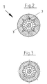
- Fig. 2
- einen Querschnitt durch den Durchflussregler gemäß
Figur 1 entlang der Linie II II vonFigur 1; - Fig. 3
- einen Querschnitt durch den Durchflussregler entlang der
Linie III III von
Figur 1 gesehen; - Fig. 4
- einen Längsschnitt durch ein erfindungsgemäßes Thermostatventil, welches sich automatisch öffnen bzw. schließen lässt;
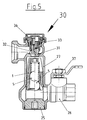
- Fig. 5
- einen Längsschnitt durch ein Ventil gemäß einer Variante der Erfindung, welches manuell geöffnet bzw. geschlossen wird;
- Fig. 6
- eine vergrößerte Einzelansicht eines Regelelements.
- Fig. 1
- a view of a flow controller according to the invention in longitudinal section;
- Fig. 2
- a cross section through the flow controller according to Figure 1 along the line II II of Figure 1;
- Fig. 3
- seen a cross section through the flow controller along the line III III of Figure 1;
- Fig. 4
- a longitudinal section through an inventive thermostatic valve which can be opened or closed automatically;
- Fig. 5
- a longitudinal section through a valve according to a variant of the invention, which is opened or closed manually;
- Fig. 6
- an enlarged individual view of a control element.
Zunächst wird auf die Figuren 1 bis 3 Bezug genommen. Die
Längsschnittdarstellung gemäß Figur 1 zeigt einen
erfindungsgemäßen Durchflussregler, welcher ein Mantelteil 1
umfasst, welches im Prinzip eine hülsenartige, teilweise zylindrische
und rohrförmige Grundform aufweist. Dieses Mantelteil 1 weist in
einem oberen Abschnitt eine zylindrische Bohrung 2 auf, innerhalb
derer sich ein Regelelement 5 axial verschieblich bewegen kann.
Figur 1 zeigt dieses Regelelement 5 in der rechten Zeichnungshälfte
in einer oberen Position und man erkennt, dass sich unterhalb des
Regelelements 5 eine Druckfeder 4 befindet. Der Pfeil über der
Schnittdarstellung zeigt die Durchflussrichtung durch den
erfindungsgemäßen Durchflussregler. Wird nun aufgrund eines
Differenzdrucks im Strömungsweg vor bzw. nach dem
Durchflussregler das Regelelement 5 beaufschlagt, dann bewegt sich
dieses gegen die Kraft der Druckfeder bei steigendem Differenzdruck
in axialer Richtung innerhalb der Bohrung 2 nach unten bis in die
Maximalposition, die in Figur 1 in der linken Zeichnungshälfte
dargestellt ist und bei der das Regelelement 5 durch einen Absatz 11
am Ende der Bohrung 2 einen Anschlag in seiner maximalen
Hubposition findet. Lässt dagegen der Druck nach, dann bewegt sich
das Regelelement 5 zurück, da es an der Unterseite von der durch die
Druckfeder 4 erzeugten Gegenkraft beaufschlagt wird. Unterhalb des
Absatzes 11 ist eine weitere Bohrung 12 in dem Mantelteil 1, die die
Druckfeder 4 aufnimmt und die, wie man sieht, einen geringeren
Querschnitt hat, als die obere Bohrung 2, wodurch der Absatz 11 am
Ende der oberen querschnittsweiteren Bohrung 2 gebildet ist. Nach
unten hin schließt sich an die Bohrung 12 mit geringerem
Durchmesser eine Gewindebohrung 13 an, die eine Justierschraube 8
aufnimmt, welche einen Innensechskant aufweist. Auf dem Kopf 13a
dieser Justierschraube 8 stützt sich die Unterseite der Druckfeder 4
ab. Dadurch besteht die Möglichkeit, durch herstellerseitiges
Justieren, indem die Justierschraube 8 weiter hereingeschraubt wird
in die Gewindebohrung 13 oder weiter aus dieser herausgeschraubt
wird, eine Feineinstellung und Eichung der ursprünglichen Federkraft
der Druckfeder 4 vorzunehmen.First, reference is made to FIGS. 1 to 3. The
1 shows a longitudinal sectional view
Flow controller according to the invention, which has a
Wie man weiterhin aus Figur 1 und auch aus den Figuren 2 und 3
erkennen kann, befinden sich in Längsrichtung, d. h., in axialer
Richtung verlaufende Nuten 3 im Bereich der Innenseite des
Mantelteils 1, wobei mehrere solcher Nuten 3 über den inneren
Umfang des Mantelteils verteilt angeordnet sind, beispielsweise acht
solcher Nuten wie man in Figur 2 erkennt. Diese Nuten 3 erstrecken
sich durch die gesamte Länge der Wandung des Mantelteils 1, sind
jedoch etwa in der unteren Hälfte des Mantelteils nach außen hin
offen, so dass sich Schlitze 3a ergeben, durch die das Wasser radial
nach außen austreten kann, wie man Figur 1 entnehmen kann. Jedoch
ist die Tiefe der Nut 3 nicht gleichbleibend, sondern im oberen
Bereich und zwar im Bereich der Bohrung 2, innerhalb derer sich das
Regelelement 5 bewegen kann, nimmt die Nuttiefe 3 ab bis zu dem
Absatz 11, wobei sich in dem Abschnitt der Wandung, der in Figur 1
links gezeigt ist, und der sich in der Bohrung 2 bis zu dem Absatz 11
erstreckt, eine etwa parabolische Kontur der Wandung des Mantelteils
1 mit weiter einwärts abnehmender Nuttiefe ergibt. Dadurch verringert
sich der Freiraum zwischen dem äußeren Umfang des Regelelements
5 und der Innenseite der Nut, so dass bei einer Stellung, in der sich
das Regelelement weiter oben befindet (siehe Figur 1 rechts) eine
größere Menge an Fluid durch die Nuten 3 fließen kann, als wenn sich
das Regelelement 5 weiter unten befindet bis zu einem minimalen
Volumenstrom, der durch die maximale in der Zeichnung gemäß Figur
1 links dargestellte Hubposition des Regelelements 5 gegeben ist, bei
der dieses auf dem Absatz 11 aufliegt. Somit wird bei zunehmendem
Differenzdruck, bei dem sich das Regelelement 5 weiter einwärts in
der Bohrung 2 in Richtung auf den Absatz 11 verschiebt, der für das
Fluid verfügbare Querschnitt immer weiter verringert. Dadurch lässt
sich innerhalb eines vorgegebenen Druckbereichs ein konstanter
Volumenstrom erzeugen. Für verschiedene gewünschte
Volumenströme kann man im Prinzip Durchflussregler mit
Regelelementen der in Figur 1 gezeigten Art verwenden, die ähnlich
aufgebaut sind, wobei man lediglich die Anzahl der vorhandenen
Nuten 3 variiert, so dass man beispielsweise bei Vorsehen von zwei
Nuten anstelle von einer Nut den Volumenstrom verdoppeln kann usw.
Um eine Ausgangsposition des Regelelements 5 vorzugeben (siehe
Figur 1, rechte Zeichnungshälfte), in der der maximale
Durchflussquerschnitt durch die Nuten zwischen Regelelement 5 und
Wandung des Mantelteils 1 gegeben ist, dient ein endseitig in das
Mantelteil 1 eingesetzter Anschlag 14.How to continue from Figure 1 and also from Figures 2 and 3
can see, are in the longitudinal direction, d. that is, in
Das Regelelement 5 weist, wie man aus Figur 1 und Figur 6 erkennt,
einen geschlossenen Boden auf, so dass es die gesamte Bohrung 2
des Mantelteils abdeckt und der Strom des Fluids nur seitlich durch
die Nuten 3 erfolgen kann, wohingegen über beispielsweise
angespritzte Dichtlippen 6, die vorzugsweise vorderseitig und
rückseitig jeweils am Umfang an dem Regelelement 5 angebracht sind
(siehe Figur 6), das Regelelement zur Innenwandung der Bohrung 2
des Mantelteils 1 hin abdichtet, so dass dort ein Nebenstrom des
Fluids verhindert wird. Dadurch wird der Volumenstrom durch den
Querschnitt der Nut 3 bzw. der Nuten definiert.As can be seen from FIG. 1 and FIG. 6, the
Nachfolgend wird der Aufbau eines beispielhaften Thermostatventils,
bei dem ein Durchflussregler gemäß Figur 1 verwendet wird, unter
Bezugnahme auf die Darstellung gemäß Figur 4 näher erläutert. Man
erkennt, dass das Ventil ein federbelastetes Huboberteil 23 aufweist,
mit einer Ventilspindel 22, die am vorderen Ende einen
Verschlusskörper 31 aufweist, der gegen einen Ventilsitz 32 im
Gehäuse bewegbar ist, um den Durchgang des Fluids durch das Ventil
zu verschließen. Es handelt sich im Prinzip um einen herkömmlichen
Thermostatventilaufsatz, bei dem die Ventilspindel 22 beispielsweise
elektrisch antreibbar ist, wobei auf der Ventilspindel 22 eine Hülse 34
sitzt, die von einer vorgespannten Feder 35 beaufschlagt wird, so
dass das Schließen des Verschlussstücks 31 gegen die Kraft der
Feder 35 erfolgt.In the following, the construction of an exemplary thermostatic valve,
in which a flow controller according to FIG. 1 is used, under
Reference to the representation of Figure 4 explained in more detail. you
recognizes that the valve has a spring-loaded
Der Durchflussregler 1 weist außerdem außen eine vorzugsweise
angeformte Dichtlippe 38 auf, wodurch eine Abdichtung zum Gehäuse
hin geschaffen wird. The
Das Ventil umfasst weiterhin ein Gehäuse mit einem im wesentlichen
zylindrischen Mittelteil 27, von dem im unteren Bereich ein erster
Eingangsstutzen 26 radial abgeht, durch den das Fluid in das
Gehäuseinnere gelangt, wobei es dann durch den Durchflussregler
mit dem Regelelement 5 strömt, das hier anders als bei der zuvor
beschriebenen Variante eine Kugel ist, wobei der Durchflussregler in
Figur 4 in einer gegenüber Figur 1 um 180° gedrehten Position
entsprechend der Durchflussrichtung des Fluids dargestellt ist.The valve further comprises a housing with an essentially
cylindrical
Das Ventilgehäuse umfasst weiterhin einen ebenfalls radial
abgehenden Ausgangsstutzen 28 im oberen Bereich unterhalb des
Ventiloberteils 23, so dass der Ausgangsstutzen 28 parallel aber mit
axialem Versatz zu dem Eingangsstutzen 26 abgeht von dem
zylindrischen Gehäusemittelteil 27. Es handelt sich also im Prinzip um
eine sogenannte Doppeleckanordnung mit zweifachem Winkelversatz
in der Strömungsrichtung, welches ermöglicht, das Gehäuse des
Thermostatventils insgesamt besonders flach zu bauen, da die
vorhandenen Stutzen alle in einer Ebene liegen. Neben dem
Eingangsstutzen 26 und dem Ausgangsstutzen 28 sind ein in axialer
Verlängerung zu dem Gehäusemittelteil 27 angeordneter weiterer
unterer Stutzen 24 vorgesehen, der endseitig in axialer Verlängerung
des Gehäusemittelteils 27 angeordnet ist sowie ein diesem am
anderen Ende gegenüberliegender kurzer Stutzen 33, der das
Ventiloberteil 23 aufnimmt, welches beispielsweise in den Stutzen
eingeschraubt werden kann. In dem Bereich zwischen dem
Gehäusemittelteil 27 und dem unteren endseitigen Stutzen 24, der
über ein einschraubbares Verschlussstück 25 verschlossen ist,
befindet sich in axialer Verlängerung zu dem Mantelteil 1 mit dem
Regelelement 5 ein ringförmiger Schmutzfänger 21, der aus einem
Drahtsieb oder einem ähnlichen siebartigen Material bestehen kann.
Wie man sieht, ist der Schmutzfänger 21 etwa in Höhe des
Eingangsstutzens 26 des Gehäuses angeordnet, so dass das dort
einströmende Fluid durch den Schmutzfänger 21 strömt und
insbesondere gröbere Partikel von diesem abgehalten werden, damit
diese nicht in den Bereich des Regelelements 5 gelangen und dessen
Beweglichkeit beeinträchtigen können.The valve housing also includes a radial one
Figur 5 zeigt eine alternative Variante der Erfindung, bei der das
Ventil im Prinzip in den Gehäuseteilen ebenso aufgebaut ist, wie das
zuvor beschriebene Ventil gemäß Figur 4. Auch bei dem Ventil gemäß
Figur 5 ist das Mantelteil 1 mit dem Regelelement 5 in dem
zylindrischen Gehäusemittelteil 27 eingesetzt. Anders als jedoch bei
der zuvor beschriebenen Thermostatventilvariante ist bei der Variante
gemäß Figur 5 ein manuell betätigbares Ventiloberteil 30 in den
Stutzen 33 eingesetzt, so dass man das Ventil durch Betätigung des
Verschlusskörpers 31, dem wiederum ein Ventilsitz 32 des Gehäuses
zugeordnet ist, das Ventil öffnen bzw. verschließen kann. Die
Durchflussrichtung und die Funktion des Durchflussreglers mit dem
Regelelement 5 entspricht im übrigen dem zuvor anhand von Figur 4
beschriebenen Ausführungsbeispiel. Durch Herausschrauben des
Verschlussstücks 25 ist das Innere des Ventilgehäuses für den
Service zugänglich und es kann beispielsweise der Durchflussregler
1, 5 ausgetauscht werden. Nach Abnehmen einer auf den oberen
Stutzen 33 aufgeschraubten Kappe 36 ist das manuell betätigbare
Ventiloberteil 30 zugänglich. Außerdem ist hier noch im Bereich des
Eingangsstutzens 26 ein betätigbarer Kugelhahn 37 angeordnet,
damit man auch hier absperren kann, wenn das Ventil z. B. zur
Wartung von unten her geöffnet werden soll. Figure 5 shows an alternative variant of the invention, in which the
In principle, the valve is constructed in the housing parts just like that
The previously described valve according to FIG. 4. Also in the valve according to
Figure 5 is the
- 1.1.
- Mantelteiljacket part
- 2.Second
- Bohrungdrilling
- 3.Third
- Nutgroove
- 4.4th
- Druckfedercompression spring
- 5.5th
- Regelelementcontrol element
- 6.6th
- Dichtelementsealing element
- 8.8th.
- Justierschraubeadjusting screw
- 11.11th
- Absatzparagraph
- 12.12th
- Bohrungdrilling
- 13.13th
- Gewindebohrungthreaded hole
- 14.14th
- Anschlagattack
- 21.21st
- Schmutzfängerstrainer
- 22.22nd
- VentilspindelValve stem
- 23.23rd
- Huboberteilupper stroke
- 24.24th
- unterer Stutzenlower neck
- 25.25th
- Verschlussstückclosing piece
- 26.26th
- Eingangsstutzeninlet connection
- 27.27th
- zylindrisches Mittelteilcylindrical middle part
- 28.28th
- Ausgangsstutzenoutlet connection
- 30.30th
- VentiloberteilValve top
- 31.31st
- Verschlusskörperclosure body
- 32.32nd
- Ventilsitzvalve seat
- 33.33rd
- StutzenSupport
- 34.34th
- Hülseshell
- 35.35th
- Federfeather
- 36.36th
- Kappecap
Claims (22)
Applications Claiming Priority (2)
| Application Number | Priority Date | Filing Date | Title |
|---|---|---|---|
| DE10205406A DE10205406A1 (en) | 2002-02-09 | 2002-02-09 | Flow controller e.g. for thermostat valve, has enclosure part with variable internal cross-section |
| DE10205406 | 2002-02-09 |
Publications (2)
| Publication Number | Publication Date |
|---|---|
| EP1341069A1 true EP1341069A1 (en) | 2003-09-03 |
| EP1341069B1 EP1341069B1 (en) | 2006-08-23 |
Family
ID=27618505
Family Applications (1)
| Application Number | Title | Priority Date | Filing Date |
|---|---|---|---|
| EP03002808A Expired - Lifetime EP1341069B1 (en) | 2002-02-09 | 2003-02-07 | Flow controller and valve with flow controller |
Country Status (4)
| Country | Link |
|---|---|
| EP (1) | EP1341069B1 (en) |
| AT (1) | ATE337577T1 (en) |
| DE (2) | DE10205406A1 (en) |
| DK (1) | DK1341069T3 (en) |
Citations (4)
| Publication number | Priority date | Publication date | Assignee | Title |
|---|---|---|---|---|
| US3093155A (en) * | 1960-06-20 | 1963-06-11 | Bendix Corp | Variable-restriction valve |
| US4383550A (en) * | 1980-11-26 | 1983-05-17 | Rikuta Sotokazu | Constant flow valve |
| DE20022166U1 (en) * | 2000-12-20 | 2001-06-21 | Huthmann, André, 27632 Midlum | Device for regulating the flow rate of a fluid medium |
| US20020100506A1 (en) * | 2000-12-18 | 2002-08-01 | May John Henry | Flow control valve |
Family Cites Families (6)
| Publication number | Priority date | Publication date | Assignee | Title |
|---|---|---|---|---|
| US3015341A (en) * | 1958-01-10 | 1962-01-02 | William Waterman | Flow regulators |
| DE1473034A1 (en) * | 1964-08-11 | 1968-11-07 | Benkisser Werk Kg | Flow regulator |
| US4306585A (en) * | 1979-10-03 | 1981-12-22 | Manos William S | Constant flow valve |
| DE3310007A1 (en) * | 1983-03-19 | 1984-09-20 | Schlösser GmbH, 5960 Olpe | Thermostat-controlled three-way directional regulating valve, in particular for single-pipe heating systems |
| WO1991010949A1 (en) * | 1990-01-08 | 1991-07-25 | Alco Standard Corporation | Fluid flow regulator |
| US5383489A (en) * | 1993-10-26 | 1995-01-24 | Flow Design, Inc. | Flow control valve with enhanced flow control piston |
-
2002
- 2002-02-09 DE DE10205406A patent/DE10205406A1/en not_active Withdrawn
-
2003
- 2003-02-07 AT AT03002808T patent/ATE337577T1/en active
- 2003-02-07 EP EP03002808A patent/EP1341069B1/en not_active Expired - Lifetime
- 2003-02-07 DE DE50304698T patent/DE50304698D1/en not_active Expired - Lifetime
- 2003-02-07 DK DK03002808T patent/DK1341069T3/en active
Patent Citations (4)
| Publication number | Priority date | Publication date | Assignee | Title |
|---|---|---|---|---|
| US3093155A (en) * | 1960-06-20 | 1963-06-11 | Bendix Corp | Variable-restriction valve |
| US4383550A (en) * | 1980-11-26 | 1983-05-17 | Rikuta Sotokazu | Constant flow valve |
| US20020100506A1 (en) * | 2000-12-18 | 2002-08-01 | May John Henry | Flow control valve |
| DE20022166U1 (en) * | 2000-12-20 | 2001-06-21 | Huthmann, André, 27632 Midlum | Device for regulating the flow rate of a fluid medium |
Also Published As
| Publication number | Publication date |
|---|---|
| DE50304698D1 (en) | 2006-10-05 |
| DE10205406A1 (en) | 2003-08-21 |
| EP1341069B1 (en) | 2006-08-23 |
| DK1341069T3 (en) | 2007-01-02 |
| ATE337577T1 (en) | 2006-09-15 |
Similar Documents
| Publication | Publication Date | Title |
|---|---|---|
| DE10325846B4 (en) | Pressure reducing regulator | |
| EP3213803B1 (en) | Filter assembly | |
| DE3150100C2 (en) | Float-controlled water inlet valve | |
| EP1516237B1 (en) | Flow rate regulator | |
| DE69217946T2 (en) | RETURN VALVE | |
| EP3362713B1 (en) | Poppet valve | |
| EP0061415A1 (en) | Valve for hydraulic systems | |
| DE3817270A1 (en) | Jet regulator | |
| DE2608791A1 (en) | MODULATING FLOW CONTROL VALVE ARRANGEMENT | |
| DE3338418C2 (en) | ||
| DE202005004196U1 (en) | Flow regulator | |
| DE202005010233U1 (en) | Lever-operated, automatic shut-off arrangement | |
| EP1341069B1 (en) | Flow controller and valve with flow controller | |
| DE102004049253B4 (en) | thermostatic valve | |
| DE10132001C2 (en) | Thermostatic controller for regulating the flow rate of a fluid | |
| DE19710983C2 (en) | check valve | |
| DE102005011947B3 (en) | Continuous flow controller, has controlling mechanisms designed for different flow rate capacities and/or pressure ranges, where one mechanism exhibits opening that acts as bypass channel, which is openable and closeable | |
| DE10156500C5 (en) | Pressure reducing valve | |
| DE202021100188U1 (en) | Sanitary assembly for generating a time-varying water jet | |
| DE102006039730B3 (en) | Cartridge valve | |
| DE69212031T2 (en) | Pneumatic connection system with an improved air control valve | |
| DE102022132067B4 (en) | Sanitary fitting and use of a sanitary fitting | |
| EP0258595B1 (en) | Sanitary armature | |
| DE20311848U1 (en) | Hose rupture valve | |
| EP1536170B1 (en) | Valve |
Legal Events
| Date | Code | Title | Description |
|---|---|---|---|
| PUAI | Public reference made under article 153(3) epc to a published international application that has entered the european phase |
Free format text: ORIGINAL CODE: 0009012 |
|
| 17P | Request for examination filed |
Effective date: 20030628 |
|
| AK | Designated contracting states |
Kind code of ref document: A1 Designated state(s): AT BE BG CH CY CZ DE DK EE ES FI FR GB GR HU IE IT LI LU MC NL PT SE SI SK TR |
|
| AX | Request for extension of the european patent |
Extension state: AL LT LV MK RO |
|
| AKX | Designation fees paid |
Designated state(s): AT BE BG CH CY CZ DE DK EE ES FI FR GB GR HU IE IT LI LU MC NL PT SE SI SK TR |
|
| RAP1 | Party data changed (applicant data changed or rights of an application transferred) |
Owner name: HONEYWELL TECHNOLOGIES SARL |
|
| GRAP | Despatch of communication of intention to grant a patent |
Free format text: ORIGINAL CODE: EPIDOSNIGR1 |
|
| GRAS | Grant fee paid |
Free format text: ORIGINAL CODE: EPIDOSNIGR3 |
|
| GRAA | (expected) grant |
Free format text: ORIGINAL CODE: 0009210 |
|
| AK | Designated contracting states |
Kind code of ref document: B1 Designated state(s): AT BE BG CH CY CZ DE DK EE ES FI FR GB GR HU IE IT LI LU MC NL PT SE SI SK TR |
|
| PG25 | Lapsed in a contracting state [announced via postgrant information from national office to epo] |
Ref country code: FI Free format text: LAPSE BECAUSE OF FAILURE TO SUBMIT A TRANSLATION OF THE DESCRIPTION OR TO PAY THE FEE WITHIN THE PRESCRIBED TIME-LIMIT Effective date: 20060823 Ref country code: SK Free format text: LAPSE BECAUSE OF FAILURE TO SUBMIT A TRANSLATION OF THE DESCRIPTION OR TO PAY THE FEE WITHIN THE PRESCRIBED TIME-LIMIT Effective date: 20060823 Ref country code: IE Free format text: LAPSE BECAUSE OF FAILURE TO SUBMIT A TRANSLATION OF THE DESCRIPTION OR TO PAY THE FEE WITHIN THE PRESCRIBED TIME-LIMIT Effective date: 20060823 Ref country code: SI Free format text: LAPSE BECAUSE OF FAILURE TO SUBMIT A TRANSLATION OF THE DESCRIPTION OR TO PAY THE FEE WITHIN THE PRESCRIBED TIME-LIMIT Effective date: 20060823 Ref country code: IT Free format text: LAPSE BECAUSE OF FAILURE TO SUBMIT A TRANSLATION OF THE DESCRIPTION OR TO PAY THE FEE WITHIN THE PRESCRIBED TIME-LIMIT;WARNING: LAPSES OF ITALIAN PATENTS WITH EFFECTIVE DATE BEFORE 2007 MAY HAVE OCCURRED AT ANY TIME BEFORE 2007. THE CORRECT EFFECTIVE DATE MAY BE DIFFERENT FROM THE ONE RECORDED. Effective date: 20060823 |
|
| REG | Reference to a national code |
Ref country code: GB Ref legal event code: FG4D Free format text: NOT ENGLISH |
|
| REG | Reference to a national code |
Ref country code: CH Ref legal event code: EP |
|
| REG | Reference to a national code |
Ref country code: IE Ref legal event code: FG4D Free format text: LANGUAGE OF EP DOCUMENT: GERMAN |
|
| REF | Corresponds to: |
Ref document number: 50304698 Country of ref document: DE Date of ref document: 20061005 Kind code of ref document: P |
|
| PG25 | Lapsed in a contracting state [announced via postgrant information from national office to epo] |
Ref country code: BG Free format text: LAPSE BECAUSE OF FAILURE TO SUBMIT A TRANSLATION OF THE DESCRIPTION OR TO PAY THE FEE WITHIN THE PRESCRIBED TIME-LIMIT Effective date: 20061123 |
|
| REG | Reference to a national code |
Ref country code: SE Ref legal event code: TRGR |
|
| PG25 | Lapsed in a contracting state [announced via postgrant information from national office to epo] |
Ref country code: ES Free format text: LAPSE BECAUSE OF FAILURE TO SUBMIT A TRANSLATION OF THE DESCRIPTION OR TO PAY THE FEE WITHIN THE PRESCRIBED TIME-LIMIT Effective date: 20061204 |
|
| GBT | Gb: translation of ep patent filed (gb section 77(6)(a)/1977) |
Effective date: 20061115 |
|
| REG | Reference to a national code |
Ref country code: DK Ref legal event code: T3 |
|
| PG25 | Lapsed in a contracting state [announced via postgrant information from national office to epo] |
Ref country code: PT Free format text: LAPSE BECAUSE OF FAILURE TO SUBMIT A TRANSLATION OF THE DESCRIPTION OR TO PAY THE FEE WITHIN THE PRESCRIBED TIME-LIMIT Effective date: 20070124 |
|
| PG25 | Lapsed in a contracting state [announced via postgrant information from national office to epo] |
Ref country code: MC Free format text: LAPSE BECAUSE OF NON-PAYMENT OF DUE FEES Effective date: 20070228 |
|
| REG | Reference to a national code |
Ref country code: IE Ref legal event code: FD4D |
|
| ET | Fr: translation filed | ||
| PLBE | No opposition filed within time limit |
Free format text: ORIGINAL CODE: 0009261 |
|
| STAA | Information on the status of an ep patent application or granted ep patent |
Free format text: STATUS: NO OPPOSITION FILED WITHIN TIME LIMIT |
|
| 26N | No opposition filed |
Effective date: 20070524 |
|
| BERE | Be: lapsed |
Owner name: HONEYWELL TECHNOLOGIES SARL Effective date: 20070228 |
|
| PG25 | Lapsed in a contracting state [announced via postgrant information from national office to epo] |
Ref country code: BE Free format text: LAPSE BECAUSE OF NON-PAYMENT OF DUE FEES Effective date: 20070228 |
|
| PG25 | Lapsed in a contracting state [announced via postgrant information from national office to epo] |
Ref country code: GR Free format text: LAPSE BECAUSE OF FAILURE TO SUBMIT A TRANSLATION OF THE DESCRIPTION OR TO PAY THE FEE WITHIN THE PRESCRIBED TIME-LIMIT Effective date: 20061124 |
|
| PG25 | Lapsed in a contracting state [announced via postgrant information from national office to epo] |
Ref country code: EE Free format text: LAPSE BECAUSE OF FAILURE TO SUBMIT A TRANSLATION OF THE DESCRIPTION OR TO PAY THE FEE WITHIN THE PRESCRIBED TIME-LIMIT Effective date: 20060823 |
|
| PG25 | Lapsed in a contracting state [announced via postgrant information from national office to epo] |
Ref country code: LU Free format text: LAPSE BECAUSE OF NON-PAYMENT OF DUE FEES Effective date: 20070207 Ref country code: CY Free format text: LAPSE BECAUSE OF FAILURE TO SUBMIT A TRANSLATION OF THE DESCRIPTION OR TO PAY THE FEE WITHIN THE PRESCRIBED TIME-LIMIT Effective date: 20060823 |
|
| PG25 | Lapsed in a contracting state [announced via postgrant information from national office to epo] |
Ref country code: HU Free format text: LAPSE BECAUSE OF FAILURE TO SUBMIT A TRANSLATION OF THE DESCRIPTION OR TO PAY THE FEE WITHIN THE PRESCRIBED TIME-LIMIT Effective date: 20070224 Ref country code: TR Free format text: LAPSE BECAUSE OF FAILURE TO SUBMIT A TRANSLATION OF THE DESCRIPTION OR TO PAY THE FEE WITHIN THE PRESCRIBED TIME-LIMIT Effective date: 20060823 |
|
| REG | Reference to a national code |
Ref country code: FR Ref legal event code: PLFP Year of fee payment: 14 |
|
| REG | Reference to a national code |
Ref country code: FR Ref legal event code: PLFP Year of fee payment: 15 |
|
| REG | Reference to a national code |
Ref country code: FR Ref legal event code: PLFP Year of fee payment: 16 |
|
| PGFP | Annual fee paid to national office [announced via postgrant information from national office to epo] |
Ref country code: NL Payment date: 20190225 Year of fee payment: 17 |
|
| PGFP | Annual fee paid to national office [announced via postgrant information from national office to epo] |
Ref country code: CH Payment date: 20190225 Year of fee payment: 17 Ref country code: IT Payment date: 20190221 Year of fee payment: 17 Ref country code: CZ Payment date: 20190206 Year of fee payment: 17 Ref country code: GB Payment date: 20190227 Year of fee payment: 17 |
|
| PGFP | Annual fee paid to national office [announced via postgrant information from national office to epo] |
Ref country code: FR Payment date: 20190226 Year of fee payment: 17 Ref country code: AT Payment date: 20190227 Year of fee payment: 17 Ref country code: SE Payment date: 20190222 Year of fee payment: 17 Ref country code: DK Payment date: 20190225 Year of fee payment: 17 |
|
| REG | Reference to a national code |
Ref country code: DK Ref legal event code: EBP Effective date: 20200229 |
|
| REG | Reference to a national code |
Ref country code: SE Ref legal event code: EUG |
|
| REG | Reference to a national code |
Ref country code: CH Ref legal event code: PL |
|
| REG | Reference to a national code |
Ref country code: NL Ref legal event code: MM Effective date: 20200301 |
|
| REG | Reference to a national code |
Ref country code: AT Ref legal event code: MM01 Ref document number: 337577 Country of ref document: AT Kind code of ref document: T Effective date: 20200207 |
|
| GBPC | Gb: european patent ceased through non-payment of renewal fee |
Effective date: 20200207 |
|
| PG25 | Lapsed in a contracting state [announced via postgrant information from national office to epo] |
Ref country code: SE Free format text: LAPSE BECAUSE OF NON-PAYMENT OF DUE FEES Effective date: 20200208 Ref country code: CZ Free format text: LAPSE BECAUSE OF NON-PAYMENT OF DUE FEES Effective date: 20200207 |
|
| PG25 | Lapsed in a contracting state [announced via postgrant information from national office to epo] |
Ref country code: CH Free format text: LAPSE BECAUSE OF NON-PAYMENT OF DUE FEES Effective date: 20200229 Ref country code: LI Free format text: LAPSE BECAUSE OF NON-PAYMENT OF DUE FEES Effective date: 20200229 Ref country code: AT Free format text: LAPSE BECAUSE OF NON-PAYMENT OF DUE FEES Effective date: 20200207 |
|
| PG25 | Lapsed in a contracting state [announced via postgrant information from national office to epo] |
Ref country code: NL Free format text: LAPSE BECAUSE OF NON-PAYMENT OF DUE FEES Effective date: 20200301 |
|
| PG25 | Lapsed in a contracting state [announced via postgrant information from national office to epo] |
Ref country code: GB Free format text: LAPSE BECAUSE OF NON-PAYMENT OF DUE FEES Effective date: 20200207 Ref country code: DK Free format text: LAPSE BECAUSE OF NON-PAYMENT OF DUE FEES Effective date: 20200229 Ref country code: FR Free format text: LAPSE BECAUSE OF NON-PAYMENT OF DUE FEES Effective date: 20200229 |
|
| PG25 | Lapsed in a contracting state [announced via postgrant information from national office to epo] |
Ref country code: IT Free format text: LAPSE BECAUSE OF NON-PAYMENT OF DUE FEES Effective date: 20200207 |
|
| PGFP | Annual fee paid to national office [announced via postgrant information from national office to epo] |
Ref country code: DE Payment date: 20220329 Year of fee payment: 20 |
|
| REG | Reference to a national code |
Ref country code: DE Ref legal event code: R071 Ref document number: 50304698 Country of ref document: DE |