EP1341280A2 - Arrangement dérivateur de surtensions, en particulier pour dispositifs de télécommunication; module dérivatuer de surtensions et arrangement de connexion de terre pour une barette de hachage - Google Patents
Arrangement dérivateur de surtensions, en particulier pour dispositifs de télécommunication; module dérivatuer de surtensions et arrangement de connexion de terre pour une barette de hachage Download PDFInfo
- Publication number
- EP1341280A2 EP1341280A2 EP03003673A EP03003673A EP1341280A2 EP 1341280 A2 EP1341280 A2 EP 1341280A2 EP 03003673 A EP03003673 A EP 03003673A EP 03003673 A EP03003673 A EP 03003673A EP 1341280 A2 EP1341280 A2 EP 1341280A2
- Authority
- EP
- European Patent Office
- Prior art keywords
- contact
- protection module
- circuit board
- connection
- surge protection
- Prior art date
- Legal status (The legal status is an assumption and is not a legal conclusion. Google has not performed a legal analysis and makes no representation as to the accuracy of the status listed.)
- Granted
Links
Images


Classifications
-
- H—ELECTRICITY
- H01—ELECTRIC ELEMENTS
- H01T—SPARK GAPS; OVERVOLTAGE ARRESTERS USING SPARK GAPS; SPARKING PLUGS; CORONA DEVICES; GENERATING IONS TO BE INTRODUCED INTO NON-ENCLOSED GASES
- H01T4/00—Overvoltage arresters using spark gaps
- H01T4/06—Mounting arrangements for a plurality of overvoltage arresters
Definitions
- the invention relates to an overvoltage protection arrangement, in particular for telecommunications devices and / or systems which have at least one separating strip have with plug contacts in grid dimensions and with the isolating strip at least has a grounding contact or grounding point, according to the preamble of Claim 1.
- the invention further relates to an overvoltage protection module in particular for an overvoltage protection arrangement for telecommunications devices and an earthing arrangement for a separating strip, the again in particular for an overvoltage protection arrangement for telecommunications devices Can be used.
- a protective module for telecommunications technology is known from German utility model DE 200 02 378 U1, which has tapping contacts for forming an electrically conductive connection with the contacts of a connection module for telecommunications technology and can be combined accordingly.
- At least one overvoltage protection component is provided there, which is connected either electrically via its contact legs, which extend parallel to a contact slot formed in the associated tapping contact, or via an adapter to the tapping contacts.
- all the tapping contacts should be essentially flat.
- the space required for the protection module is considerable and there are problems with the formation of particularly current-carrying earth connections.
- the surge protection magazine has a housing that contains several surge arresters each have an earth contact. There is also an earth rail with the earth contacts are conductively connected. An earth tap is on the exception of the earth tap itself completely assembled surge protection magazine can be retrofitted in such a way that contact is made with the earth rail.
- the earth tap is designed to snap into place, with the housing of the surge protection magazine a locking hook is provided which in one in the earth tap trained recess engages when the earth tap at the intended location is introduced into the surge protection magazine.
- Terminal strips for telecommunications technology belong to the prior art and are known for example from DE 200 00 506 U1.
- Such terminal strips can also include an integrated grounding section or element have at least one contact area to form an electrical conductive connection with a surge protection component and other contacts to form an electrically conductive connection with different carrier systems having.
- the terminal block according to DE 200 00 506 U1 has two laterally integrated earth contacts, so that a plugged-in surge protection module also receives the necessary connection to ground or earth.
- a housing is provided for the surge protection magazine according to WO 99/56361, which consists of several individual parts, with a large number of tapping contacts with a section extending from the back of the case and attached State contacts of the establishment of the telecommunications technology taps.
- An earth contact is also provided there and it is in the surge protection magazine several surge arresters can be used, the legs have in the inserted state with the corresponding contacts are directly electrically connectable.
- the structure there, in particular regarding the use of the individual surge protection elements is very time consuming as it is not easily possible to put all the items in not cohesively contact a work step at the same time.
- WO 99/54965 discloses a similar arrangement of a protective plug for a device in telecommunications technology. There, the surge protection components are fixed directly to the contacts without a printed circuit board using clamping slots.
- Another object of the invention is to develop a further Surge protection arrangement, in particular for telecommunications devices and / or systems to be specified, which is generally inexpensive to manufacture, which has the required surge current carrying capacity and which easily and can be easily replaced.
- Another object of the invention is in specifying a special surge protection module that is very small Installation space includes energetically coordinated surge arresters, each one Form a group for several pairs of a known isolating strip.
- the surge protection arrangement and in particular the Surge protection module to be designed so that it fits the miniaturized Connection technology is, especially here on the so-called RCT (Rapid Contact Technology).
- the object of the invention is achieved with an overvoltage protection arrangement, especially for telecommunications equipment, according to the Features of claim 1, with an overvoltage protection module according to the features of claim 3 and with an earthing arrangement according to the features of claim 1 (?), the subclaims at least represent expedient refinements and developments.
- the surge protection arrangement according to the invention in particular for Telecommunications facilities and / or systems, goes from one in itself known separation strip, in particular for the so-called RCT connection technology.
- a separating strip has plug contacts in grid dimensions and also has the possibility of making earth connections.
- a surge protection module for a plurality of Twin wires of the isolating strip are provided, with the surge protection module has a wiring support, in particular a printed circuit board.
- the circuit board has quasi integral contact pins at one end the pitch of the plug contacts of the isolating strip and carries a group of energetically coordinated surge arresters, which according to the respective Protective circuit are wired.
- surge arresters include e.g. Varistors and gas arresters.
- the surge protection module has at least one earth connection, which lies in the plane of the contact pins, and is surrounded by a housing which only or at least the sections of the ground connection and the contact pins leaves free.
- the surge protection module can now be inserted from above into the corresponding Plug contacts of the isolating strip are inserted and fixed there, also at plugged surge arrester or module, the routing of outgoing wires is easily possible and the labeling of the bar remains visible.
- one or more surge protection modules are integrated in the Separating strip can be inserted, by plugging in the electrical connection between the plug contacts and the contact pins on the one hand and the Ground connection and the ground contact on the other hand is formed.
- the earth contact within the isolating strip has an earthing bracket which has at least two notched or bent tabs which engage in slot-shaped cutouts in the isolating strip base body.
- the tabs are preferably located on the side next to a group of plug contacts.
- the earthing clip also has contact claws for making the external earth connection, for example via a mounting trough or similar means.
- the earthing bracket with the tabs and the contact claws can be retrofitted into the separating strip base. Alternatively, the earthing bracket can already be located in the mounting trough and the earthing bracket is positioned in the slot-shaped recesses when the isolating strip is attached.
- the surge protection module according to the invention which is particularly for The aforementioned surge protection arrangement for telecommunications equipment can be used with separating strips, consists of a printed circuit board, a wiring carrier for both semiconductor and gas arrester surge protection components, which is energetically coordinated and electrically connected are, forms.
- the gas arresters are accommodated by a fixing body, which has cutouts corresponding to the external dimensions of the respective gas arrester (s).
- the fixing body has openings on its bottom side, each of which receives a connection contact wire of the respective gas arrester.
- the gas conductor connecting contact wires passed through the openings are connected to corresponding contact areas on the printed circuit board by soldering.
- a common contact plate is provided for the mating contacts of the gas discharge tube, the contact plate comprising recesses with spring clamping in accordance with the position of the mating contacts, so that when the contact plate is put on, all mating contacts are electrically connected together in one step.
- the contact plate has angled tongues, at least one tongue one Ground connection and at least one other tongue forms the fixing body outside encompasses and with an earth connection point on the circuit board side force and / or is cohesively connected.
- Contact pins or the circuit board are formed at one end of the circuit board itself is structured in such a way that several quasi-integral pins are created.
- the pin spacing then corresponds to the specified grid dimension of the separating strip or there provided mother contacts.
- the at least one tongue for the earth connection is arranged laterally adjacent to the contact pins, in such a way that An earth contact can be made with the tabs of the earthing bracket.
- the gas arresters extend with their connections essentially perpendicular to PCB level, with the contact pins lying in the PCB level itself or run accordingly.
- the contact plate can have two laterally opposite, outer earthing tongues and two inner, the fixing body have tabs on the sides.
- the contact plate is preferably a metallic one Stamped-bent part executed, each recess for the counter contacts the gas arrester has several spring claws oriented towards the center, which enter into a positive / positive connection with the respective connecting wire of the arrester.
- the contact pins of the circuit board and the at least one tongue for the Grounding means are designed as father contacts.
- the spring claws of the contact plate can each form a plate spring, which provides mechanical resistance to the connecting wire when inserted, so that a safe, low-resistance and permanent electrical contact given is.
- the fixing body consists of an insulating plastic and the recesses are designed as multi-row chambers. Furthermore, the fixing body has lateral Extensions that lead around the circuit board in a lateral section.
- the side wall of the fixing body also has at least one groove for the Picking up at least one other tongue.
- the fixing body can be pre-assembled with a corresponding gas arrester Form assembly aid.
- the grounding arrangement for a isolating strip in particular for an overvoltage protection arrangement, assumes a separating strip base body, which has several, has slot-shaped recesses spaced apart in the grid.
- a proposed one Grounding bracket includes tabs, which when inserted into the recesses of the Basic body are guided by these.
- the grounding bracket also has Contact claws or protrusions connected to earth. This earth connection can, for example, via a separating strip holder or separating strip mounting tray getting produced.
- the surge protection module described above comprising a Contact plate with spring elements, are when the contact plate is attached the printed circuit board connected all equipped gas arresters to the contact plate.
- the Contact sheet is designed as stated so that it is the grounding point for the Surge protection device suitable for isolating strips of the Rapid Contact system represents.
- the side tabs or tongues hold the contact plate on the circuit board and simultaneously form an electrical connection.
- the contact plate made of solid metal ensures the desired high surge current carrying capacity the arrangement achieved with mechanical stability.
- the contact plate 1 shown in FIG. 1 is a metallic stamped and bent part executed and has rear tongues 4, the fixing body 5 (Fig. 3) and Grasp circuit board 2.
- the rear tongues 4 have a lower, inward bend.
- the area of this offset then simultaneously forms a solder connection section with a connection panel located on the underside of the printed circuit board 2.
- front tongues 6 are formed on the contact plate 1, which are the ground connection form.
- the top surface of the contact plate 1 comprises recesses 7, each one Pick up the connecting wire of a gas arrester 3.
- the area of the recesses 7 in the contact plate 1 is spring-loaded Provide properties or form a plate spring itself.
- the lateral offset dimension of the front tongues 6 is on the width of the circuit board 2 and the contact pins 8 located there at one end.
- the front tongues 6 can then when inserting the complete module 10 in a known separating strip 11 in contact with corresponding tabs 12 a Ground strap 13 kick.
- the contact plate 1 is from above placed on the fixing body 5 and contacted all in one step Connection wires of the gas arrester 3.
- the fixing body 5 has a large number of cutouts, which correspond to the external dimensions the respective gas arrester are matched, and includes bottom Openings (not shown) that each receive the other connection contact wire. These other connection contact wires are then made with appropriate ones Contact surfaces that are on the back of the PCB by soldering connected.
- the gas traps 3 are essentially perpendicular to their connections Level of the circuit board 2, the contact pins 8 being in the circuit board level extend.
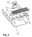
- a grounding bracket 13 is in the partition 11 Rapid Contact Systems inserted.
- the trained on the earthing bracket 13, e.g. notched tabs 12 provide two grounding points for each complete module 10 to disposal.
- the earthing clip When attaching the separating strip 11 to the mounting trough 15, the earthing clip becomes 13 electrically connected to this.
- the earthing to the mounting trough 15 is made the earth strap 13 made.
- the Isolating strip 11 up to four surge protection devices, i.e. Complete modules 10 that Contact ten single wires each, insertable.
- others are Versions of the isolating strip for one or two surge protection devices in the In terms of the invention lying.
- Two grounding points are available for each surge protection device provided, in connection with the contact plate for sufficient Current carrying capacity is ensured. The contact itself takes place when it is pushed open the separating strip on the mounting tray, so that no additional effort arises.
Landscapes
- Emergency Protection Circuit Devices (AREA)
Applications Claiming Priority (2)
| Application Number | Priority Date | Filing Date | Title |
|---|---|---|---|
| DE10208698 | 2002-02-28 | ||
| DE10208698A DE10208698B4 (de) | 2002-02-28 | 2002-02-28 | Überspannungsschutz-Modul, Überspannungsschutz-Anordnung, insbesondere für Telekommunikations-Einrichtungen, sowie Erdungsanordnung für die Trennleiste der Überspannungs-Schutzanordnung |
Publications (3)
| Publication Number | Publication Date |
|---|---|
| EP1341280A2 true EP1341280A2 (fr) | 2003-09-03 |
| EP1341280A3 EP1341280A3 (fr) | 2009-10-07 |
| EP1341280B1 EP1341280B1 (fr) | 2011-09-21 |
Family
ID=27675115
Family Applications (1)
| Application Number | Title | Priority Date | Filing Date |
|---|---|---|---|
| EP03003673A Expired - Lifetime EP1341280B1 (fr) | 2002-02-28 | 2003-02-18 | Arrangement dérivateur de surtensions, en particulier pour dispositifs de télécommunication; module dérivatuer de surtensions et arrangement de connexion de terre pour une barette de hachage |
Country Status (3)
| Country | Link |
|---|---|
| EP (1) | EP1341280B1 (fr) |
| AT (1) | ATE525776T1 (fr) |
| DE (1) | DE10208698B4 (fr) |
Family Cites Families (10)
| Publication number | Priority date | Publication date | Assignee | Title |
|---|---|---|---|---|
| DE8902245U1 (de) * | 1989-02-25 | 1989-05-11 | Thomas & Betts Corp., Bridgewater, N.J. | Vielfachstecker |
| DE4005942A1 (de) * | 1990-02-26 | 1991-08-29 | Dehn & Soehne | Ueberspannungsschutzstecker fuer trennleisten |
| FR2732164B1 (fr) * | 1995-03-20 | 1997-04-30 | Alcatel Cable Interface | Reglette de connexion de lignes a haut debit et ensemble resultant de connexion |
| US5627721A (en) * | 1995-07-14 | 1997-05-06 | Lucent Technologies Inc. | Protector cartridge for modular connector blocks |
| DE19816907B4 (de) * | 1998-04-16 | 2006-09-28 | Quante Ag | Schutzstecker für eine Einrichtung der Telekommunikationstechnik |
| DE19818477A1 (de) * | 1998-04-24 | 1999-10-28 | Quante Ag | Überspannungsschutzmagazin für eine Einrichtung der Telekommunikationstechnik |
| US6166894A (en) * | 1999-03-15 | 2000-12-26 | Lucent Technologies Inc. | PCB based protector cartridge |
| DE19917824A1 (de) * | 1999-04-20 | 2000-10-26 | Quante Ag | Überspannungsschutzmagazin |
| DE20000506U1 (de) * | 2000-01-13 | 2000-03-16 | Quante Ag, 42109 Wuppertal | Anschlussleiste der Telekommunikationstechnik |
| DE20002378U1 (de) * | 2000-02-11 | 2000-04-27 | Quante Ag, 42109 Wuppertal | Schutzmodul der Telekommunikationstechnik |
-
2002
- 2002-02-28 DE DE10208698A patent/DE10208698B4/de not_active Expired - Fee Related
-
2003
- 2003-02-18 EP EP03003673A patent/EP1341280B1/fr not_active Expired - Lifetime
- 2003-02-18 AT AT03003673T patent/ATE525776T1/de active
Also Published As
| Publication number | Publication date |
|---|---|
| DE10208698B4 (de) | 2004-03-04 |
| ATE525776T1 (de) | 2011-10-15 |
| DE10208698A1 (de) | 2003-10-02 |
| EP1341280B1 (fr) | 2011-09-21 |
| EP1341280A3 (fr) | 2009-10-07 |
Similar Documents
| Publication | Publication Date | Title |
|---|---|---|
| EP0709917B1 (fr) | Bloc de connexion avec module électronique | |
| EP0272200B1 (fr) | Bloc de connexion pour les télécommunications | |
| EP2862364B1 (fr) | Module de branchement de répartiteur | |
| DE10317621B4 (de) | Überspannungsschutzmagazin für eine Einrichtung der Telekommunikationstechnik | |
| EP3241261B1 (fr) | Dispositif de protection contre des surtensions pour la technique des informations et des télécommunications | |
| EP2608323B1 (fr) | Liaison pour passage de boîtier | |
| DE102005042163B3 (de) | Schutzstecker für ein Anschlussmodul | |
| DE19617114C2 (de) | Erdungsmodul | |
| DE19547557A1 (de) | Elektrische Klemmen mit steckbaren Querbrückern | |
| DE3730662C2 (fr) | ||
| EP0952635B1 (fr) | Connecteur électrique | |
| DE102013017157B4 (de) | Vorrichtung zur Montage mindestens eines als Steckmodul ausgebildeten Überspannungsschutzgeräts | |
| DE102011101201B4 (de) | Verteileranschlussmodul und Verfahren zur Beschaltung eines Verteileranschlussmoduls | |
| DE3901307C2 (de) | Elektrische Anschlußklemme | |
| BE1026787B1 (de) | Anschlussvorrichtung für elektrische Leiter | |
| DE10208698B4 (de) | Überspannungsschutz-Modul, Überspannungsschutz-Anordnung, insbesondere für Telekommunikations-Einrichtungen, sowie Erdungsanordnung für die Trennleiste der Überspannungs-Schutzanordnung | |
| DD297285A5 (de) | Verteilerleiste fuer eine telekommunikationsanlage | |
| DE102008046653B4 (de) | Bauelementestecker | |
| EP0413978A2 (fr) | Dispositif de protection pour un distributeur dans une installation de télécommunication | |
| DE29909701U1 (de) | Schutzstecker für eine Einrichtung der Telekommunikationstechnik | |
| DE10120720A1 (de) | Erdungsvorrichtung und Erdungseinrichtung für eine Verteilereinrichtung und Handhabungsvorrichtung zum Montieren einer Erdungsvorrichtung sowie Schutzstecker und Verteilereinrichtung | |
| DE102013003389B4 (de) | Baugruppe bestehend aus mindestens zwei benachbart zueinander angeordneten elektrischen Anschlussklemmen und einem Querverbinder | |
| DE102011016062B4 (de) | Verteileranschlussmodul | |
| DE1803669C3 (de) | Anordnung der für den Überspannungsschutz von Fernmeldekabelendverschlüssen in Kabelverzweigergehäusen erforderlichen Elemente | |
| EP1846944A1 (fr) | Appareil de commutation electromagnetique, en particulier un contacteur electromagnetique |
Legal Events
| Date | Code | Title | Description |
|---|---|---|---|
| PUAI | Public reference made under article 153(3) epc to a published international application that has entered the european phase |
Free format text: ORIGINAL CODE: 0009012 |
|
| AK | Designated contracting states |
Kind code of ref document: A2 Designated state(s): AT BE BG CH CY CZ DE DK EE ES FI FR GB GR HU IE IT LI LU MC NL PT SE SI SK TR |
|
| AX | Request for extension of the european patent |
Extension state: AL LT LV MK RO |
|
| PUAL | Search report despatched |
Free format text: ORIGINAL CODE: 0009013 |
|
| AK | Designated contracting states |
Kind code of ref document: A3 Designated state(s): AT BE BG CH CY CZ DE DK EE ES FI FR GB GR HU IE IT LI LU MC NL PT SE SI SK TR |
|
| AX | Request for extension of the european patent |
Extension state: AL LT LV MK RO |
|
| 17P | Request for examination filed |
Effective date: 20091027 |
|
| 17Q | First examination report despatched |
Effective date: 20091210 |
|
| AKX | Designation fees paid |
Designated state(s): AT BE BG CH CY CZ DE DK EE ES FI FR GB GR HU IE IT LI LU MC NL PT SE SI SK TR |
|
| GRAP | Despatch of communication of intention to grant a patent |
Free format text: ORIGINAL CODE: EPIDOSNIGR1 |
|
| GRAS | Grant fee paid |
Free format text: ORIGINAL CODE: EPIDOSNIGR3 |
|
| GRAA | (expected) grant |
Free format text: ORIGINAL CODE: 0009210 |
|
| AK | Designated contracting states |
Kind code of ref document: B1 Designated state(s): AT BE BG CH CY CZ DE DK EE ES FI FR GB GR HU IE IT LI LU MC NL PT SE SI SK TR |
|
| REG | Reference to a national code |
Ref country code: GB Ref legal event code: FG4D Free format text: NOT ENGLISH |
|
| REG | Reference to a national code |
Ref country code: CH Ref legal event code: EP |
|
| REG | Reference to a national code |
Ref country code: IE Ref legal event code: FG4D Free format text: LANGUAGE OF EP DOCUMENT: GERMAN |
|
| REG | Reference to a national code |
Ref country code: DE Ref legal event code: R096 Ref document number: 50313957 Country of ref document: DE Effective date: 20111117 |
|
| REG | Reference to a national code |
Ref country code: NL Ref legal event code: VDEP Effective date: 20110921 |
|
| PG25 | Lapsed in a contracting state [announced via postgrant information from national office to epo] |
Ref country code: SE Free format text: LAPSE BECAUSE OF FAILURE TO SUBMIT A TRANSLATION OF THE DESCRIPTION OR TO PAY THE FEE WITHIN THE PRESCRIBED TIME-LIMIT Effective date: 20110921 Ref country code: FI Free format text: LAPSE BECAUSE OF FAILURE TO SUBMIT A TRANSLATION OF THE DESCRIPTION OR TO PAY THE FEE WITHIN THE PRESCRIBED TIME-LIMIT Effective date: 20110921 |
|
| PG25 | Lapsed in a contracting state [announced via postgrant information from national office to epo] |
Ref country code: SI Free format text: LAPSE BECAUSE OF FAILURE TO SUBMIT A TRANSLATION OF THE DESCRIPTION OR TO PAY THE FEE WITHIN THE PRESCRIBED TIME-LIMIT Effective date: 20110921 Ref country code: CY Free format text: LAPSE BECAUSE OF FAILURE TO SUBMIT A TRANSLATION OF THE DESCRIPTION OR TO PAY THE FEE WITHIN THE PRESCRIBED TIME-LIMIT Effective date: 20110921 Ref country code: GR Free format text: LAPSE BECAUSE OF FAILURE TO SUBMIT A TRANSLATION OF THE DESCRIPTION OR TO PAY THE FEE WITHIN THE PRESCRIBED TIME-LIMIT Effective date: 20111222 |
|
| REG | Reference to a national code |
Ref country code: IE Ref legal event code: FD4D |
|
| PG25 | Lapsed in a contracting state [announced via postgrant information from national office to epo] |
Ref country code: IE Free format text: LAPSE BECAUSE OF FAILURE TO SUBMIT A TRANSLATION OF THE DESCRIPTION OR TO PAY THE FEE WITHIN THE PRESCRIBED TIME-LIMIT Effective date: 20110921 Ref country code: SK Free format text: LAPSE BECAUSE OF FAILURE TO SUBMIT A TRANSLATION OF THE DESCRIPTION OR TO PAY THE FEE WITHIN THE PRESCRIBED TIME-LIMIT Effective date: 20110921 Ref country code: CZ Free format text: LAPSE BECAUSE OF FAILURE TO SUBMIT A TRANSLATION OF THE DESCRIPTION OR TO PAY THE FEE WITHIN THE PRESCRIBED TIME-LIMIT Effective date: 20110921 |
|
| PGFP | Annual fee paid to national office [announced via postgrant information from national office to epo] |
Ref country code: FR Payment date: 20120316 Year of fee payment: 10 |
|
| PG25 | Lapsed in a contracting state [announced via postgrant information from national office to epo] |
Ref country code: PT Free format text: LAPSE BECAUSE OF FAILURE TO SUBMIT A TRANSLATION OF THE DESCRIPTION OR TO PAY THE FEE WITHIN THE PRESCRIBED TIME-LIMIT Effective date: 20120123 Ref country code: EE Free format text: LAPSE BECAUSE OF FAILURE TO SUBMIT A TRANSLATION OF THE DESCRIPTION OR TO PAY THE FEE WITHIN THE PRESCRIBED TIME-LIMIT Effective date: 20110921 Ref country code: NL Free format text: LAPSE BECAUSE OF FAILURE TO SUBMIT A TRANSLATION OF THE DESCRIPTION OR TO PAY THE FEE WITHIN THE PRESCRIBED TIME-LIMIT Effective date: 20110921 |
|
| PGFP | Annual fee paid to national office [announced via postgrant information from national office to epo] |
Ref country code: IT Payment date: 20120228 Year of fee payment: 10 |
|
| PLBE | No opposition filed within time limit |
Free format text: ORIGINAL CODE: 0009261 |
|
| STAA | Information on the status of an ep patent application or granted ep patent |
Free format text: STATUS: NO OPPOSITION FILED WITHIN TIME LIMIT |
|
| PG25 | Lapsed in a contracting state [announced via postgrant information from national office to epo] |
Ref country code: DK Free format text: LAPSE BECAUSE OF FAILURE TO SUBMIT A TRANSLATION OF THE DESCRIPTION OR TO PAY THE FEE WITHIN THE PRESCRIBED TIME-LIMIT Effective date: 20110921 |
|
| 26N | No opposition filed |
Effective date: 20120622 |
|
| BERE | Be: lapsed |
Owner name: DEHN + SOHNE G.M.B.H. + CO KG Effective date: 20120228 |
|
| PG25 | Lapsed in a contracting state [announced via postgrant information from national office to epo] |
Ref country code: MC Free format text: LAPSE BECAUSE OF NON-PAYMENT OF DUE FEES Effective date: 20120229 |
|
| REG | Reference to a national code |
Ref country code: CH Ref legal event code: PL |
|
| REG | Reference to a national code |
Ref country code: DE Ref legal event code: R097 Ref document number: 50313957 Country of ref document: DE Effective date: 20120622 |
|
| GBPC | Gb: european patent ceased through non-payment of renewal fee |
Effective date: 20120218 |
|
| PG25 | Lapsed in a contracting state [announced via postgrant information from national office to epo] |
Ref country code: LI Free format text: LAPSE BECAUSE OF NON-PAYMENT OF DUE FEES Effective date: 20120229 Ref country code: CH Free format text: LAPSE BECAUSE OF NON-PAYMENT OF DUE FEES Effective date: 20120229 |
|
| REG | Reference to a national code |
Ref country code: DE Ref legal event code: R119 Ref document number: 50313957 Country of ref document: DE Effective date: 20120901 |
|
| PG25 | Lapsed in a contracting state [announced via postgrant information from national office to epo] |
Ref country code: BE Free format text: LAPSE BECAUSE OF NON-PAYMENT OF DUE FEES Effective date: 20120228 |
|
| PG25 | Lapsed in a contracting state [announced via postgrant information from national office to epo] |
Ref country code: GB Free format text: LAPSE BECAUSE OF NON-PAYMENT OF DUE FEES Effective date: 20120218 |
|
| REG | Reference to a national code |
Ref country code: AT Ref legal event code: MM01 Ref document number: 525776 Country of ref document: AT Kind code of ref document: T Effective date: 20120218 |
|
| PG25 | Lapsed in a contracting state [announced via postgrant information from national office to epo] |
Ref country code: ES Free format text: LAPSE BECAUSE OF FAILURE TO SUBMIT A TRANSLATION OF THE DESCRIPTION OR TO PAY THE FEE WITHIN THE PRESCRIBED TIME-LIMIT Effective date: 20120101 |
|
| PG25 | Lapsed in a contracting state [announced via postgrant information from national office to epo] |
Ref country code: DE Free format text: LAPSE BECAUSE OF NON-PAYMENT OF DUE FEES Effective date: 20120901 Ref country code: AT Free format text: LAPSE BECAUSE OF NON-PAYMENT OF DUE FEES Effective date: 20120218 Ref country code: BG Free format text: LAPSE BECAUSE OF FAILURE TO SUBMIT A TRANSLATION OF THE DESCRIPTION OR TO PAY THE FEE WITHIN THE PRESCRIBED TIME-LIMIT Effective date: 20111221 |
|
| REG | Reference to a national code |
Ref country code: FR Ref legal event code: ST Effective date: 20131031 |
|
| PG25 | Lapsed in a contracting state [announced via postgrant information from national office to epo] |
Ref country code: IT Free format text: LAPSE BECAUSE OF NON-PAYMENT OF DUE FEES Effective date: 20130218 |
|
| PG25 | Lapsed in a contracting state [announced via postgrant information from national office to epo] |
Ref country code: FR Free format text: LAPSE BECAUSE OF NON-PAYMENT OF DUE FEES Effective date: 20130228 |
|
| PG25 | Lapsed in a contracting state [announced via postgrant information from national office to epo] |
Ref country code: TR Free format text: LAPSE BECAUSE OF FAILURE TO SUBMIT A TRANSLATION OF THE DESCRIPTION OR TO PAY THE FEE WITHIN THE PRESCRIBED TIME-LIMIT Effective date: 20110921 |
|
| PG25 | Lapsed in a contracting state [announced via postgrant information from national office to epo] |
Ref country code: LU Free format text: LAPSE BECAUSE OF NON-PAYMENT OF DUE FEES Effective date: 20120218 |
|
| PG25 | Lapsed in a contracting state [announced via postgrant information from national office to epo] |
Ref country code: HU Free format text: LAPSE BECAUSE OF FAILURE TO SUBMIT A TRANSLATION OF THE DESCRIPTION OR TO PAY THE FEE WITHIN THE PRESCRIBED TIME-LIMIT Effective date: 20030218 |