EP1341393A2 - Noeud pour un réseau optique, et réseau optique - Google Patents
Noeud pour un réseau optique, et réseau optique Download PDFInfo
- Publication number
- EP1341393A2 EP1341393A2 EP03100464A EP03100464A EP1341393A2 EP 1341393 A2 EP1341393 A2 EP 1341393A2 EP 03100464 A EP03100464 A EP 03100464A EP 03100464 A EP03100464 A EP 03100464A EP 1341393 A2 EP1341393 A2 EP 1341393A2
- Authority
- EP
- European Patent Office
- Prior art keywords
- lsp
- path
- establishment
- node
- section
- Prior art date
- Legal status (The legal status is an assumption and is not a legal conclusion. Google has not performed a legal analysis and makes no representation as to the accuracy of the status listed.)
- Granted
Links
Images

















Classifications
-
- H—ELECTRICITY
- H04—ELECTRIC COMMUNICATION TECHNIQUE
- H04Q—SELECTING
- H04Q11/00—Selecting arrangements for multiplex systems
- H04Q11/0001—Selecting arrangements for multiplex systems using optical switching
- H04Q11/0062—Network aspects
-
- H—ELECTRICITY
- H04—ELECTRIC COMMUNICATION TECHNIQUE
- H04Q—SELECTING
- H04Q11/00—Selecting arrangements for multiplex systems
- H04Q11/0001—Selecting arrangements for multiplex systems using optical switching
- H04Q11/0062—Network aspects
- H04Q11/0066—Provisions for optical burst or packet networks
-
- H—ELECTRICITY
- H04—ELECTRIC COMMUNICATION TECHNIQUE
- H04Q—SELECTING
- H04Q11/00—Selecting arrangements for multiplex systems
- H04Q11/0001—Selecting arrangements for multiplex systems using optical switching
- H04Q11/0062—Network aspects
- H04Q11/0071—Provisions for the electrical-optical layer interface
-
- H—ELECTRICITY
- H04—ELECTRIC COMMUNICATION TECHNIQUE
- H04Q—SELECTING
- H04Q11/00—Selecting arrangements for multiplex systems
- H04Q11/0001—Selecting arrangements for multiplex systems using optical switching
- H04Q11/0062—Network aspects
- H04Q2011/0086—Network resource allocation, dimensioning or optimisation
Definitions
- the present invention relates to a photonic network of a multi-layered structure comprising optical paths upon optical wavelengths and electrical paths which use the optical paths.
- the present invention relates to a path establishment method in a multi-layer photonic network, which is required for implementing cooperative operation of a high capacity photonic path network which is implemented with photonic cross connect devices, and a service network which is implemented with Layer 2/3 switches, which typically are IP routers or the like.
- the present invention is applicable to a multi-layer photonic network which is an electrical/optical path integrated communication network.
- the present invention concerns the technical field of traffic engineering related to methods and procedures for establishing and releasing optical paths dynamically according to traffic quantities between sub-networks.
- photonic network which comprises a plurality of sub-networks which perform switching and transfer by units of packets, optical transmission lines which connect these sub-networks, and nodes which terminate these optical transmission lines.
- optical wavelength switching capability which is the capability of switching by optical wavelength units
- PSC packet switching capability
- this type of photonic network possesses such a two-layered structure including both O-LSPs and E-LSPs, it is termed a multi-layer photonic network. Since when performing IP transfer of packets with this type of multi-layer photonic network, the transmission upon some intermediate paths is performed as optical signal packets by O-LSPs. Accordingly, as compared with the case of the transfer along the entire path being performed as electrical signal packets, it is possible to obtain the great variety of beneficial effects which an optical transmission line possesses, such as being able to have great transmission speed and/or multiplicity.
- the O-LSPs and the E-LSPs are managed independently, so that it is not possible to modify the O-LSPs freely according to the demand upon the E-LSPs or the traffic fluctuation.
- each of the O-LSPs operates fixedly via a common carrier leased line or the like, there are the problems that their provision cannot respond to the fluctuations of the packet traffic immediately, and that it is not possible efficiently to make the best possible use of the O-LSP resources. Furthermore there is the problem that, when varying the O-LSP provision, it is necessary to make application to the photonic network administrator, and it is also necessary for the photonic network administrator to change over and establish the O-LSPs manually, and the like.
- each node calculates a path in its own most efficient manner by every node in the photonic network having the same path establishment information, this is troublesome, because it is not necessary to advertise the information regarding a path which is established in order to respond to temporary increase in traffic, to all of the nodes.
- a photonic network is constructed using an optical transmission line and nodes which terminate this optical transmission line.
- a plurality of sub-networks are connected to the photonic network, and these sub-networks are mutually interconnected by electrical paths.
- These electrical paths include one or a plurality of optical paths belonging to the photonic network.
- the optical paths and the electrical paths are managed independently, and it has not been possible freely to vary the optical paths according to the demand for the electrical paths or the fluctuations of traffic or the like.
- node devices have progressively been introduced which at the present have a throughput in the Tbit/sec range, and it is anticipated that in the near future the next generation of devices will have throughputs of 10 to 100 Tbits/sec or greater.
- a photonic router By using such a photonic router, it becomes possible more closely to cooperate a conventional type of IP network which operates by packet switching (PSC), and a high capacity photonic path network (hereinafter termed a photonic network) which operates by optical switching (LSC).
- PSC packet switching
- LSC optical switching
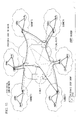
- FIG. 53 shows a multi-layer photonic network.
- the multi-layer photonic network shown in FIG. 53 comprises a photonic core network and several electrical packet switching sub-networks.
- the multi-layer photonic network of FIG. 53 is a multi-layered network, in which optical paths are established over the photonic core network, while electrical path switching sub-network groups which are connected together by these optical paths constitute the overall structure of the electrical packet switching network.
- the photonic core network comprises a plurality of photonic cross connects (PXCs) and a plurality of optical fiber cables which link between these PXCs.
- PXCs photonic cross connects
- optical fiber cables which link between these PXCs.
- optical paths by optical fiber cables are established over the photonic core network, and mutually connect together different ones of the electrical packet switching sub-networks. Information is transparently transferred between the different electrical packet switching sub-networks over these optical paths.
- FIGS. 54A to 54C show a state of affairs in which it is possible to implement two types of electrical packet switching network topology (FIGS. 54B and 54C) when a single optical path network topology has been provided (FIG. 54A).
- the optical paths are denoted by the symbol O-LSP, while the electrical paths are denoted by the symbol E-LSP.
- the E-LSPs are routed upon the overall electrical packet switching network which is made up from the electrical packet switching sub-networks which are mutually connected together by the O-LSPs.
- the E-LSPs are connected together in multiple hop routing.
- two of the electrical packet switching sub-networks are connected together via two of the O-LSPs in series.
- the E-LSPs are connected together with a single hop.
- two of the electrical packet switching sub-networks are connected together via a single one of the O-LSPs.
- the overall electrical packet switching network must possess a "connected" structure, in the terminology of graph theory.
- FIGS. 55A to 55C show a connected electrical packet switching network (FIG. 55B), and a non-connected electrical packet switching network (FIG. 55C).
- the conventional type BXCQ scheme has been known as a means for solution of the dynamic optical path topology optimization problem, which is one part of the problem which the present invention seeks to address.
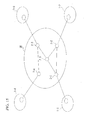
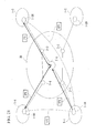
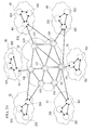
- FIG. 56 shows an example in which the four electrical packet switching sub-networks shown in FIG. 53 are mutually connected together.
- the electrical packet switching sub-network 1 is directly connected to the electrical packet switching sub-networks 2 and 3 by optical paths; and, similarly, the electrical packet switching sub-network 2 is connected directly to the electrical packet switching sub-networks 1 and 4 by optical paths, the electrical packet switching sub-network 3 is connected directly to the electrical packet switching sub-networks 1 and 4 by optical paths, and the electrical packet switching sub-network 4 is connected directly to the electrical packet switching sub-networks 2 and 3 by optical paths.
- FIG. 57 shows an example in which, just as in FIG. 56, the four electrical packet switching sub-networks shown in FIG. 53 are mutually connected together, but in this case optical paths are established along diagonal paths between the electrical packet switching sub-networks 1 and 4, and between the electrical packet switching sub-networks 2 and 3.
- an electrical border router upon the boundary of each of the electrical packet switching sub-networks is provided with two electrical packet transmission/reception ports connected to the photonic core network.
- the configuration shown in FIG. 56 is the most advantageous one; while, on the contrary, if this diagonal traffic is high, then the configuration shown in FIG. 57 is the most advantageous one.
- optical paths are established without any consideration of the quantity of the traffic, then, for example, it may be the case that no direct optical path is established between some pair of the electrical packet switching sub-networks between which the packet transfer traffic is heavy, and then a necessity may arise for such packet transfer to be performed by multiple hop routing, which may lead to occurrence of the problem of congestion arising upon the optical paths.
- the mutual traffic quantities between the electrical packet switching sub-networks can be determined by counting the number of packets which flow over the E-LSPs, or by counting the number of bytes in the packets.
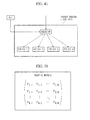
- the mutual traffic between all of the electrical packet switching sub-networks can be expressed in the form of a matrix, and this is termed the traffic matrix.
- FIG. 58 An example of a traffic matrix is shown in FIG. 58.
- a traffic matrix for a network which is made up of N electrical packet switching sub-networks, and the (i, j)-th component of the matrix represents the quantity of traffic between the electrical packet switching sub-networks i and j.
- the traffic varies with time, so that, even after an optical path has been established for the time being, it may later become necessary dynamically to re-establish the optical path according to the current conditions.
- the present invention has been conceived against this background, and it takes as its objective to propose a multi-layer photonic network, a node, a program, a recording medium, and a path establishment method with which efficient operation can be anticipated, by each node calculating the most suitable paths and automatically establishing O-LSPs and E-LSPs.
- the present invention is distinguished by the fact that the path establishment for the O-LSPs is controlled by the nodes of the E-LSPs which include the O-LSPs.
- path establishment for O-LSPs as occasion may require is performed according to the traffic conditions upon the nodes of the E-LSPs, so that it is possible to implement efficient management of a multi-layer photonic network.
- the first aspect of the present invention is a multi-layer photonic network, comprising a plurality of sub-networks which perform switching and transfer in units of packets, optical transmission lines which are connected between these sub-networks, and nodes which terminate these optical transmission lines; and having a two layer construction consisting of O-LSPs provided with LSC at both their ends, and E-LSPs which include the O-LSPs and have PSC at both their ends, and wherein, at both ends of the optical wavelength links which are constituted by the optical transmission lines and the nodes, there are provided both LSC which is capable of switching in units of optical wavelengths and also PSC which is capable of switching in units of packets.
- the distinguishing feature of the present invention is that there is provided a section which automatically establishes a path for an O-LSP according to an establishment request for an E-LSP while taking account of path information which includes path cost, resource consumption, and traffic quantity.
- the second aspect of the present invention is a node which is applied in the multi-layer photonic network of the present invention, and which is particularly distinguished by comprising a section which automatically establishes a path for the O-LSP according to an establishment request for the E-LSP while taking account of path information which includes path cost, resource consumption, and traffic quantity.
- the establishment section comprises: a calculation section. provided to the node which requests establishment of the E-LSP, which calculates a path for the O-LSP; and a section, provided to the node on the destination side of the O-LSP, which establishes the path of the O-LSP based upon the result of calculation by the calculation section.
- the node which requests the establishment of an E-LSP conjointly to perform O-LSP path establishment. Accordingly, since it is possible for a user uses an E-LSP to perform even as much as path establishment of an O-LSP which is included therein in response to a request, along with it being possible to enhance the convenience to the user, the network manager is not required himself to perform path establishment of O-LSPs, and furthermore, by the most suitable O-LSP path establishment being provided in response to the traffic conditions of the E-LSP, it is possible to reduce the trouble of O-LSP path establishment, and it is therefore possible to perform multi-layer photonic network management at high efficiency.
- the establishment section may comprise a section, provided to the node which requests establishment of the E-LSP, which calculates a path for the O-LSP, and which issues a path establishment request based upon the result of the calculation; and a section, provided to the node on the destination side of the O-LSP, which, after having received the path establishment request, makes a decision as to whether or not it is possible to establish a path based upon the calculation result which is included in the path establishment request; and, if such establishment is possible, establishes a path based upon the calculation result; while on the other hand, if such establishment is not possible, it calculates the path for a second time, and establishes the path of the O-LSP.
- the establishment section may comprise a section, provided to the node which requests establishment of the E-LSP, which issues a path establishment request for the O-LSP; and a section, provided to a node which can establish the O-LSP, which: performs calculation of the path of the O-LSP based upon the path establishment request, makes a decision as to whether or not it is possible to establish the O-LSP, and, along with communicating the results thereof to the section which issues the path establishment request, establishes the O-LSP, if such establishment is possible.
- the node which requests the establishment of an E-LSP does not perform path calculation of an O-LSP; and furthermore, it does not perform establishment of the path of the O-LSP either; rather, the path calculation for the O-LSP and the establishment of the O-LSP are entrusted to a node which is capable thereof. By doing this, the load upon the node which requests the establishment of the E-LSP is alleviated.
- the node which requests the establishment of the E-LSP may perform the path establishment request for the O-LSP to a node which is capable of establishing the O-LSP, and in this case, the node which requests the establishment of the E-LSP may select a node which is capable of establishing the O-LSP which is best from the point of view of its own convenience. By doing this, it is possible to ensure a path and an optical wavelength at high probability.
- the path establishment request issuing section may comprise a section which issues a path establishment request by selecting, as the node at which the O-LSP can be established, that node for which the hop number from the current node or the total cost of the link is the minimum.
- the establishment section may comprise a section, provided to the node which requests the establishment of the O-LSP, which issues a path establishment request for the O-LSP; and a section, provided to a node which can establish the O-LSP, which: performs calculation of the path of the O-LSP based upon the path establishment request, makes a decision as to whether or not it is possible to establish the O-LSP, and communicates the result thereof to the section which issues the path establishment request; and the path establishment request issuing section may comprise a section for, if a plurality of communications to the effect that path establishment is possible have arrived from the communication section of a plurality of nodes, actually requesting the establishment of the O-LSP to that node, from among the nodes that have issued the communications to the effect that path establishment is possible, from which the communication to the effect that establishment is possible has arrived most quickly, or for which the hop number from the current node or the total cost of the link is the minimum.
- the node which requests the establishment of an E-LSP does not perform path calculation of an O-LSP; and furthermore, it does not perform establishment of the path of the O-LSP either; rather, the path calculation for the O-LSP and the establishment of the O-LSP are entrusted to a node which is capable thereof. By doing this, the load upon the node which requests the establishment of the E-LSP is alleviated.
- the node which requests the establishment of the E-LSP may perform path establishment requests for an O-LSP to a plurality of nodes which are capable of establishing the O-LSP; and, in this case, the node which requests the establishment of the E-LSP may select, from among a plurality of nodes which are capable of establishing the O-LSP and from which communication has arrived to the effect that establishment is possible, that node which is capable of establishing the O-LSP which is best from the point of view of its own convenience.
- the node which is capable of establishing the O-LSP which is best from the point of view of its own convenience may be, for example, the node from which the communication to the effect that establishment is possible has arrived most quickly, or for which the hop number from the current node or the total cost of the link is the minimum. By doing this, it is possible to ensure a path and an optical wavelength at high probability.
- a third aspect of the present invention is a program which, by being installed upon an information processing device, implements upon the information processing device a function which corresponds to a node which is employed in the multi-layer photonic network of the present invention.
- the feature by which the present invention is particularly distinguished is that a function is implemented of automatically establishing a path for an O-LSP according to an establishment request for an E-LSP while taking account of path information which includes path cost, resource consumption, and traffic quantity.
- the establishment function it is desirable to implement a function of calculating a path for the O-LSP, provided to the node which requests establishment of the E-LSP, and a function which establishes the path of the O-LSP based upon the result of calculation by the calculation function, provided to the node on the destination side of the O-LSP.
- the establishment function there may be implemented a function, provided to the node which requests establishment of the E-LSP, of calculating a path for the O-LSP, and of issuing a path establishment request based upon the result of the calculation; and a function, provided to the node on the destination side of the O-LSP, of, after having received the path establishment request, making a decision as to whether or not it is possible to establish a path based upon the calculation result which is included in the path establishment request; and, if such establishment is possible, establishing a path based upon the calculation result; while on the other hand, if such establishment is not possible, calculating the path for a second time, and establishing the path of the O-LSP.
- the establishment function there may be implemented a function, provided to the node which requests establishment of the E-LSP, for issuing a path establishment request for the O-LSP; and a function, provided to a node which can establish the O-LSP, which: performs calculation of the path of the O-LSP based upon the path establishment request, makes a decision as to whether or not it is possible to establish the O-LSP, and, along with communicating the results thereof to the section for issuing the path establishment request, establishes the O-LSP, if such establishment is possible.
- the establishment function there may be implemented a function, provided to the node which requests the establishment of the O-LSP, of issuing a path establishment request for the O-LSP; and a function, provided to a node which can establish the O-LSP, of: performing calculation of the path of the O-LSP based upon the path establishment request, making a decision as to whether or not it is possible to establish the O-LSP, and communicating the result thereof to the function which issues the path establishment request; and, as the path establishment request issuing function, there may be implemented a function of, if a plurality of communications to the effect that path establishment is possible have arrived from the communication section of a plurality of nodes, actually requesting the establishment of the O-LSP to that node, from among the nodes that have issued the communications to the effect that path establishment is possible, from which the communication to the effect that establishment is possible has arrived most quickly, or for which the hop number from the current node or the total cost of the link is the minimum.
- a fourth aspect of the present invention is a recording medium which can be read by the information processing device, upon which the program according to the present invention is recorded.
- recording the program of the present invention upon the recording medium of the present invention it is possible to install the program of the present invention upon the information processing device by using this recording medium.
- a fifth aspect of the present invention is a path establishment method which is utilized in a multi-layer photonic network of the present invention, and which is particularly distinguished by the feature that, according to the E-LSP establishment request, a path for the O-LSP is automatically established while taking account of path information which includes path cost, resource consumption, and traffic quantity.
- the path for the O-LSP is calculated at the node which requests the establishment of the E-LSP, and for the path of the O-LSP to be established based upon the result of the calculation by the node on the destination side of the O-LSP.
- a path establishment request for the O-LSP to be issued from the node which requests establishment of the E-LSP; and, by a node which can establish the O-LSP, calculation of the path of the O-LSP to be performed based upon the path establishment request, a decision to be made as to whether or not it is possible to establish the O-LSP, and, along with communicating the results thereof to the node which issued the path establishment request, the O-LSP to be established, if such establishment is possible.
- a path establishment request it is desirable for a path establishment request to be issued by. for example, selecting as that node at which the O-LSP can be established, that node for which the hop number from the current node or the total cost of the link is the least.
- a path establishment request for the O-LSP to be issued; by a node which can establish the O-LSP, calculation of the path of the O-LSP to be performed based upon the path establishment request, a decision to be made as to whether or not it is possible to establish the O-LSP, and the result thereof to be communicated to the node which issued the path establishment request; and, if the node has received communications to the effect that path establishment is possible from a plurality of nodes, the establishment of the O-LSP to be actually requested to that node, from among the nodes that have issued the communications to the effect that path establishment is possible, from which the communication to the effect that establishment is possible has arrived most quickly, or for which the hop number from the current node or the total cost of the link is the minimum.
- each node calculates and automatically establishing the most suitable path for O-LSPs and E-LSPs.
- the present invention is particularly distinguished by the feature that operation of the network at high efficiency is implemented by alleviating the processing load upon all the nodes by preventing the spreading of topology information updating in relation to negligible path establishment or to the establishment of a path which is released over a short time period to the entire network, by suppressing its advertisement to the entire network.
- a sixth aspect of the present invention is a path establishment information advertisement method which is utilized for a multi-layer photonic network having a two layer construction consisting of optical wavelength links (termed “O-LSP”s) having optical wavelength switching capability (LSC) which is capable of switching in units of optical wavelengths at both their ends, and packet links (termed “E-LSP”s) which include the O-LSPs and have packet switching capability (PSC) which is capable of switching in units of packets at both their ends, and comprising a plurality of sub-networks which perform switching and transfer in units of packets, optical transmission lines which are connected between these sub-networks, and nodes which terminate these optical transmission lines; and wherein, at both ends of the optical wavelength links which are constituted by the optical transmission lines and the nodes, there are provided both LSC and also PSC.
- O-LSP optical wavelength switching capability
- E-LSP packet links
- PSC packet switching capability
- the particular characteristic of the present invention is that, when newly establishing an O-LSP or an E-LSP, the node related to the establishment of the O-LSP or the E-LSP retains the establishment information for the O-LSP or the E-LSP, and advertises it to all the nodes, only provided that a specified condition is satisfied.
- traffic is not present upon the newly established O-LSP or E-LSP of an amount which exceeds a threshold value which is established in common for the network as a whole, to shift the traffic to another O-LSP or E-LSP, and to release the newly established O-LSP or E-LSP.
- the specified condition may be, for example, that the newly established O-LSP or E-LSP has not been released even after a predetermined time period has elapsed.
- the specified condition may be, for example, that an E-LSP has been established in the newly established O-LSP after a predetermined time period has elapsed of priority which is greater than a threshold value which determines the level of the priority among the priorities which are allocated when establishing E-LSPs.
- this type of high priority E-LSP may be predicted that the traffic quantity will be large even without observing the traffic quantity, so that, since it may be predicted that the newly established O-LSP will continue in existence over a long time period, accordingly its advertisement to all the nodes is performed.
- the E-LSP When, after a predetermined time period has elapsed, in a newly established O-LSP, an E-LSP has been established of which the priority does not exceed a threshold value which determines the level of the priority among the priorities which are allocated when establishing the E-LSPs, the E-LSP may be shifted to another O-LSP or E-LSP, and the newly established O-LSP may be released.
- an O-LSP which has not been advertised is established under the pre-supposition that it will be released within a short time period, and, when an E-LSP of high priority is established over this type of O-LSP, it becomes necessary to re-advertise this O-LSP as an O-LSP which is established to continue over a long time period; and, since the procedures for such re-advertisement are troublesome, with the present invention, it is desirable for the establishment of a high priority E-LSP over an O-LSP whose advertisement has not been performed to be prohibited.
- a seventh aspect of the present invention is a node which is used for a multi-layer photonic network having a two layer construction consisting of optical wavelength links (termed “O-LSP”s) having optical wavelength switching capability (LSC) which is capable of switching in units of optical wavelengths at both their ends, and packet links (termed “E-LSP”s) which include the O-LSPs and have packet switching capability (PSC) which is capable of switching in units of packets at both their ends, and comprising a plurality of sub-networks which perform switching and transfer in units of packets, optical transmission lines which are connected between these sub-networks, and nodes which terminate these optical transmission lines; wherein, at both ends of the optical wavelength links which are constituted by the optical transmission lines and the nodes, there are provided both LSC and also PSC.
- OFP optical wavelength switching capability
- LSC optical wavelength switching capability
- this node is a node related to a newly established O-LSP or an E-LSP, this node retains the establishment information for the O-LSP or the E-LSP, and advertises it to all the nodes, only provided that a specified condition is satisfied.
- a section which releases the O-LSP or E-LSP if after a predetermined time period has elapsed no traffic is present upon the newly established O-LSP or E-LSP, or if, although traffic is present after a predetermined time period has elapsed, the traffic can be shifted to another O-LSP or E-LSP.
- a section which, if, after a predetermined time period has elapsed, traffic is not present upon the newly established O-LSP or E-LSP of an amount which exceeds a threshold value which is established in common for the network as a whole, shifts the traffic to another O-LSP or E-LSP, and releases the newly established O-LSP or E-LSP.
- the specified condition may, for example, be the condition that the newly established O-LSP or E-LSP has not been released by the release section even after a predetermined time period has elapsed.
- the specified condition may, for example, be the condition that an E-LSP has been established in the newly established O-LSP after a predetermined time period has elapsed of priority which is greater than a threshold value which determines the level of the priority among the priorities which are allocated when establishing E-LSPs.
- a section which, when, after a predetermined time period has elapsed, in a newly established O-LSP, an E-LSP has been established of which the priority does not exceed a threshold value which determines the level of the priority among the priorities which are allocated when establishing the E-LSPs, shifts the E-LSP to another O-LSP or E-LSP, and releases the newly established O-LSP.
- An eighth aspect of the present invention is a multi-layer photonic network whose particular feature is that it comprises a node according to the present invention.
- a ninth aspect of the present invention is a program which, by being installed upon an information processing device, implements upon the information processing device a function of controlling a node which is used for a multi-layer photonic network having a two layer construction consisting of optical wavelength links (termed “O-LSP”s) having optical wavelength switching capability (LSC) which is capable of switching in units of optical wavelengths at both their ends, and packet links (termed “E-LSP”s) which include the O-LSPs and have packet switching capability (PSC) which is capable of switching in units of packets at both their ends, and comprising a plurality of sub-networks which perform switching and transfer in units of packets, optical transmission lines which are connected between these sub-networks, and nodes which terminate these optical transmission lines; wherein, at both ends of the optical wavelength links which are constituted by the optical transmission lines and the nodes, there are provided both LSC and PSC.
- OFP optical wavelength switching capability
- LSC optical wavelength switching capability
- the particular distinguishing feature of the present invention is that there is further implemented a function for, when this node is a node related to a newly established O-LSP or an E-LSP, this node retaining the establishment information for the O-LSP or the E-LSP, and advertising it to all the nodes, only provided that a specified condition is satisfied.
- the specified condition may, for example, be the condition that the newly established O-LSP or E-LSP has not been released by the release section even after a predetermined time period has elapsed.
- the specified condition may, for example, be the condition that an E-LSP has been established in the newly established O-LSP after a predetermined time period has elapsed of priority which is greater than a threshold value which determines the level of the priority among the priorities which are allocated when establishing E-LSPs.
- this node is a node related to a newly established O-LSP or E-LSP for which the advertisement by the advertising section has not been performed, and an establishment request for a new O-LSP or E-LSP arrives from another node, refusing the establishment request.
- a tenth aspect of the present invention is a recording medium which can be read by the information processing device, upon which the program according to the present invention is recorded.
- recording the program of the present invention upon the recording medium of the present invention it is possible to install the program of the present invention upon the information processing device by using this recording medium.
- an information processing device such as a computer device or the like, it is possible to keep the advertisement of the establishment information for the optical paths and for the electrical paths to the necessary minimum level, so that it is possible to implement a multi-layer photonic network and a node which can be anticipated to operate at high efficiency.
- the present invention by keeping the advertisement of the establishment information for the optical paths and for the electrical paths to the necessary minimum level, that it is possible for the multi-layer photonic network to operate at high efficiency.
- the present invention takes as an objective to propose a multi-layer photonic network, an optical relay router, a program, and a recording medium which are capable of performing establishment, alteration, and release of optical paths autonomously according to demand upon electrical paths.
- the present invention is one which can take efficient advantage of network resources by suitably changing or releasing optical paths using nodes and border routers which are provided with PSC or LSC, in order to implement establishment of electrical paths.
- an eleventh aspect of the present invention is a multi-layer photonic network, and it is distinguished in that it comprises a plurality of sub-networks which perform switching and transfer in units of packets, optical transmission lines which are mutually connected between this plurality of sub-networks, and nodes which terminate these optical transmission lines; in which, at the end points of the optical wavelength links which are connected mutually between the nodes, and between the nodes and border routers within the sub-networks, there are provided optical wavelength switching section which perform switching in units of optical wavelengths, or packet switching section which perform switching in units of packets; and by comprising optical paths, both ends of which are connected to the packet switching section, and electrical paths, both ends of which are connected to the packet switching section, and which are made using one or a plurality of the optical paths.
- the path of the optical path is calculated by taking as an object this type of optical wavelength link.
- an optical wavelength link which is provided with LSC at both of its ends as a relay for optical path.
- an optical wavelength link which is provided at one of its ends with LSC and at the other of its ends with PSC as an end portion of an optical path.
- optical relay router which comprises the packet switching section and the optical wavelength switching section, and to make this optical relay router so that a portion of the input and output ports of the optical wavelength switching section are connected to the packet switching section.
- a twelfth aspect of the present invention is an optical relay router which is used in the multi-layer photonic network of the present invention, comprising the packet switching section and the optical wavelength switching section, and in which a portion of the input and output ports of the optical wavelength switching section are connected to the packet switching section.
- a thirteenth aspect of the present invention is a program which, by being installed upon an information processing device, implements upon the information processing device, as a function which corresponds to a device which is employed in the multi-layer photonic network of the present invention: a function of calculating a path for the optical path, taking as object an optical wavelength link which comprises the optical wavelength switching section at least at one of its ends; and a function of calculating a path for the electrical path based upon the path of the optical path which has been calculated by this calculation function.
- a fourteenth aspect of the present invention is a recording medium which can be read by the information processing device, upon which the program according to the present invention is recorded.
- recording the program of the present invention upon the recording medium of the present invention it is possible to install the program of the present invention upon the information processing device by using this recording medium.
- an information processing device such as a computer or the like, it is possible to implement a multi-layer photonic network in which it is possible to perform establishment, alteration, and release of optical paths autonomously, in response to demand upon electrical paths.
- the present invention aims to solve the above described problems, and it takes as its objective to make it possible newly to establish optical paths dynamically according to requests for accommodation of packet traffic, and moreover to perform new establishment of the most suitable optical paths according to the conditions of network load.
- a fifteenth aspect of the present invention is, in a multi-layer network comprising a packet network which comprises optical path links and packet switches, and a photonic network which comprises fiber links which accommodate the packet network and optical switches, to perform accommodation of packet traffic between specified grounds by searching out the path for which the optical path link cost, as seen from the point of view of the packet network, is minimum; and only to perform new establishment of an optical path if it is impossible for the packet traffic to reach the destination via an already established optical path.
- a sixteenth aspect of the present invention is, in the above described fifteenth aspect of the present invention, to perform the new establishment of the optical path when it is impossible for the packet traffic which is to be accommodated to reach the destination via an already established optical path within a number of hops which is determined in advance.
- a seventeenth aspect of the present invention is, in a multi-layer network comprising a packet network which comprises optical path links and packet switches, and a photonic network which comprises fiber links which accommodate the packet network and optical switches, to perform accommodation of packet traffic between specified grounds by searching out the path for which the fiber link cost, as seen from the point of view of the photonic network, is minimum; and only to perform new establishment of an optical path if it is impossible for the packet traffic upon the path to reach the destination via an already established optical path.
- An eighteenth aspect of the present invention is, in the above described seventeenth aspect of the present invention, to perform the new establishment of the optical path when it is impossible for the packet traffic which is to be accommodated to reach the destination via an already established optical path within a number of hops which is determined in advance.
- a nineteenth aspect of the present invention is, in a multi-layer network comprising a packet network which comprises optical path links and packet switches, and a photonic network which comprises fiber links which accommodate the packet network and optical switches, to perform new establishment of an optical path in response to a request for accommodation of packet traffic between specified grounds, and, at this time, newly to establish the optical path upon a path for which the fiber link cost, as seen from the point of view of the photonic network, is minimum.
- the present invention takes as an objective to propose a multi-layer photonic network, a program, a recording medium, and a traffic engineering method for the network, with which it is possible to perform establishment, release, and rearrangement of the most suitable O-LSPs or E-LSPs dynamically according to the traffic which changes over time.
- the present invention is particularly distinguished by the feature that rearrangement of all the E-LSPs is performed in response to detection of congestion upon any one of the O-LSPs in the network. By doing this, it is possible to perform establishment, release, and rearrangement of the most suitable O-LSPs or E-LSPs dynamically according to the traffic which changes over time.
- the O-LSP may be conjointly perform rearrangement of the O-LSPs along with the rearrangement of all the E-LSPs. For example, it may be decided whether or not it is possible newly to make an O-LSP in a single hop by which is made the E-LSP whose bandwidth used is the widest, or whose hop number is the largest, or whose path cost is the highest, and, if it is possible to do so, the O-LSP may be newly made.
- E-LSPs and O-LSPs may be newly established or rearranged according to a predetermined policy.
- the policy may, for example, include a policy of, in regard to a request to make a new E-LSP: deciding whether or not it is possible to accommodate the E-LSP in an already established O-LSP of a single hop; if such accommodation is possible, thus accommodating it; if it is not possible to accommodate the E-LSP in an already established O-LSP of a single hop, deciding whether or not it is possible to accommodate the E-LSP in an already established O-LSP whose hop number is within a predetermined hop number; if such accommodation is possible, thus accommodating it; if it is not possible to accommodate the E-LSP in an already established O-LSP whose hop number is within the predetermined hop number, deciding whether or not it is possible to make a newly established O-LSP of a single hop; and, if it is possible to make one, accommodating the E-LSP in the newly established O-LSP.
- a policy of, in regard to a request to make a new E-LSP deciding whether or not it
- an attempt is made to implement the E-LSP in a single hop; but, if this implementation is difficult, an attempt is made to implement the E-LSP within the predetermined hop number. By doing this, the flow of traffic is made smooth, and it is possible to take advantage of network resources efficiently.
- the policy may, for example, include a policy of, in regard to a request to make a new E-LSP: deciding whether or not it is possible to accommodate the E-LSP in an already established O-LSP of a single hop; if such accommodation is possible, thus accommodating it; if it is not possible to accommodate the E-LSP in an already established O-LSP of a single hop, deciding whether or not it is possible to make a newly established O-LSP of a single hop; if it is possible to make one, accommodating the E-LSP in the newly established O-LSP; if it is not possible to make the newly established O-LSP, deciding whether or not it is possible to accommodate the E-LSP in an already established O-LSP whose hop number is within a predetermined hop number; and, if such accommodation is possible, thus accommodating it.
- a policy of, in regard to a request to make a new E-LSP deciding whether or not it is possible to accommodate the E-LSP in an already established O-LSP
- the policy by making an attempt, as far as possible, to implement the E-LSP in a single hop, the flow of traffic is made smooth, and it is possible to take advantage of network resources efficiently.
- the policy may, for example, include a policy of, in regard to a request to make a new E-LSP: deciding whether or not it is possible to make a newly established O-LSP of a single hop which accommodates the E-LSP; if it is possible to make one, newly establishing the O-LSP and accommodating the E-LSP in it; if it is not possible to make one, deciding whether or not it is possible to accommodate the E-LSP in an already established O-LSP of a single hop; if such accommodation is possible, accommodating the E-LSP in the already established O-LSP; if it is not possible to accommodate the E-LSP in the already established O-LSP, deciding whether or not it is possible to accommodate the E-LSP in an already established O-LSP whose hop number is within a predetermined hop number; and, if such accommodation is possible, thus accommodating it.
- a policy of, in regard to a request to make a new E-LSP deciding whether or not it is possible to make a
- a structure of a newly established O-LSP is attempted; and, if this is impossible, an attempt is made to take advantage of an already established O-LSP, so that it is possible to perform the rearrangement procedure at a higher speed, as compared to the case of initially searching through the O-LSPs which are already established.
- the policy may, for example, include a policy of, in regard to a request to make a new E-LSP: deciding whether or not it is possible to accommodate the E-LSP by making a single newly established O-LSP whose hop number is within a predetermined hop number; if such accommodation is possible, accommodating the E-LSP in the newly established O-LSP, and, at this time, if a plurality of candidates for the newly established O-LSP are available, selecting from among the candidates the one for which, after accommodating the E-LSP, the path cost is the minimum; while, if it is not possible to accommodate the E-LSP by making such a single newly established O-LSP, deciding whether or not it is possible to accommodate the E-LSP by making up to M newly established O-LSPs whose hop number is within the predetermined hop number; and, if it is possible to make them, accommodating the E-LSP by distributing it among the up to M newly established O-LSPs.
- an attempt is made to implement the E-LSP in a single hop; but, if this implementation is difficult, an attempt is made to implement the E-LSP by distributing it over a plurality of O-LSPs within the predetermined hop number. By doing this, the flow of traffic is made smooth, and it is possible to take advantage of network resources efficiently.
- a twentieth aspect of the present invention is a multi-layer photonic network having a two layer construction consisting of optical wavelength links (termed “O-LSP”s) having optical wavelength switching capability (LSC) which is capable of switching in units of optical wavelengths at both their ends, and packet links (termed “E-LSP”s) which include the O-LSPs and have packet switching capability (PSC) which is capable of switching in units of packets at both their ends, and comprising a plurality of sub-networks which perform switching and transfer in units of packets, optical transmission lines which are connected between these sub-networks, and nodes which terminate these optical transmission lines; wherein, at both ends of the optical wavelength links which are constituted by the optical transmission lines and the nodes, there are provided both LSC and also PSC.
- OFP optical wavelength switching capability
- LSC optical wavelength switching capability
- the particular distinguishing feature of the present invention is that a rearrangement section is provided for performing rearrangement of all the E-LSPs in response to detection of congestion upon any one of the O-LSPs.
- the rearrangement section comprises a section for conjointly performing rearrangement of the O-LSPs along with the rearrangement of all the E-LSPs.
- the conjointly performing section may, for example, comprise a section for deciding whether or not it is possible newly to make an O-LSP in a single hop by which is made the E-LSP whose bandwidth used is the widest, or whose hop number is the largest, or whose path cost is the highest, and, if it is possible to do so, newly making the O-LSP.
- the conjointly performing section may comprise a rearrangement simulation section which performs rearrangement of the O-LSPs virtually a plurality of times, and a section for actually executing that rearrangement of the O-LSPs, from among the results of rearrangement performed by the rearrangement simulation section a plurality of times, whose path cost is the least.
- the rearrangement simulation section comprises a section for restricting the number of times, or the time period, for which the rearrangement of the O-LSPs is virtually performed.
- the rearrangement simulation section comprises a section for performing the rearrangement of the O-LSPs virtually by cut and try
- the actual execution section to comprise a section for actually rearranging the O-LSPs according to the order of the cut and try which has been performed virtually.
- the policy may, for example, include a policy of, in regard to a request to make a new E-LSP: deciding whether or not it is possible to accommodate the E-LSP in an already established O-LSP of a single hop; if such accommodation is possible, thus accommodating it; if it is not possible to accommodate the E-LSP in an already established O-LSP of a single hop, deciding whether or not it is possible to accommodate the E-LSP in an already established O-LSP whose hop number is within a predetermined hop number; if such accommodation is possible, thus accommodating it; if it is not possible to accommodate the E-LSP in an already established O-LSP whose hop number is within the predetermined hop number, deciding whether or not it is possible to make a newly established O-LSP of a single hop; and, if it is possible to make one, accommodating the E-LSP in the newly established O-LSP.
- a policy of, in regard to a request to make a new E-LSP deciding whether or not it
- the policy may, for example, include a policy of, in regard to a request to make a new E-LSP: deciding whether or not it is possible to accommodate the E-LSP in an already established O-LSP of a single hop; if such accommodation is possible, thus accommodating it; if it is not possible to accommodate the E-LSP in an already established O-LSP of a single hop, deciding whether or not it is possible to make a newly established O-LSP of a single hop; if it is possible to make one, accommodating the E-LSP in the newly established O-LSP; if it is not possible to make the newly established O-LSP, deciding whether or not it is possible to accommodate the E-LSP in an already established O-LSP whose hop number is within a predetermined hop number; and, if such accommodation is possible, thus accommodating it.
- a policy of, in regard to a request to make a new E-LSP deciding whether or not it is possible to accommodate the E-LSP in an already established O-LSP
- the policy may, for example, include a policy of, in regard to a request to make a new E-LSP: deciding whether or not it is possible to make a newly established O-LSP of a single hop which accommodates the E-LSP; if it is possible to make one, newly establishing the O-LSP and accommodating the E-LSP in it; if it is not possible to make one, deciding whether or not it is possible to accommodate the E-LSP in an already established O-LSP of a single hop; if such accommodation is possible, accommodating the E-LSP in the already established O-LSP; if it is not possible to accommodate the E-LSP in the already established O-LSP, deciding whether or not it is possible to accommodate the E-LSP in an already established O-LSP whose hop number is within a predetermined hop number; and, if such accommodation is possible, thus accommodating it.
- a policy of, in regard to a request to make a new E-LSP deciding whether or not it is possible to make a
- the policy may, for example, include a policy of, in regard to a request to make a new E-LSP: deciding whether or not it is possible to accommodate the E-LSP by making a single newly established O-LSP whose hop number is within a predetermined hop number; if such accommodation is possible, accommodating the E-LSP in the newly established O-LSP, and, at this time, if a plurality of candidates for the newly established O-LSP are available, selecting from among the candidates the one for which, after accommodating the E-LSP, the path cost is the minimum; while, if it is not possible to accommodate the E-LSP by making such a single newly established O-LSP, deciding whether or not it is possible to accommodate the E-LSP by making up to M newly established O-LSPs whose hop number is within the predetermined hop number; and, if it is possible to make them, accommodating the E-LSP by distributing it among the up to M newly established O-LSPs.
- section for performing rearrangement it is desirable to provide a section for performing rearrangement with the exception of E-LSPs of the already established bandwidth reservation type.
- a twenty-first aspect of the present invention is a program which, by being installed upon an information processing device, implements upon the information processing device a function which is applied in the multi-layer network of the present invention; and, here, the feature by which the present invention is particularly distinguished is that a function is implemented of performing rearrangement of all the E-LSPs in response to detection of congestion upon any one of the O-LSPs.
- a function may be implemented of deciding whether or not it is possible newly to make an O-LSP in a single hop by which is made the E-LSP whose bandwidth used is the widest, or whose hop number is the largest, or whose path cost is the highest, and, if it is possible to do so, newly making the O-LSP.
- a rearrangement simulation function of performing rearrangement of the O-LSPs virtually a plurality of times, and a function of actually executing that rearrangement of the O-LSPs, from among the results of rearrangement performed by the rearrangement simulation function a plurality of times, whose path cost is the minimum.
- the rearrangement simulation function a function of limiting the number of times or the time period that the virtual rearrangement of the O-LSPs is performed.
- a function may be implemented of, in regard to a request to make a new E-LSP, newly establishing or arranging E-LSPs and O-LSPs according to a predetermined policy.
- the policy may, for example, include a policy of, in regard to a request to make a new E-LSP: deciding whether or not it is possible to accommodate the E-LSP in an already established O-LSP of a single hop; if such accommodation is possible, thus accommodating it; if it is not possible to accommodate the E-LSP in an already established O-LSP of a single hop, deciding whether or not it is possible to accommodate the E-LSP in an already established O-LSP whose hop number is within a predetermined hop number; if such accommodation is possible, thus accommodating it; if it is not possible to accommodate the E-LSP in an already established O-LSP whose hop number is within the predetermined hop number, deciding whether or not it is possible to make a newly established O-LSP of a single hop; and, if it is possible to make one, accommodating the E-LSP in the newly established O-LSP.
- a policy of, in regard to a request to make a new E-LSP deciding whether or not it
- the policy may, for example, include a policy of, in regard to a request to make a new E-LSP: deciding whether or not it is possible to accommodate the E-LSP in an already established O-LSP of a single hop; if such accommodation is possible, thus accommodating it; if it is not possible to accommodate the E-LSP in an already established O-LSP of a single hop, deciding whether or not it is possible to make a newly established O-LSP of a single hop; if it is possible to make one, accommodating the E-LSP in the newly established O-LSP; if it is not possible to make the newly established O-LSP, deciding whether or not it is possible to accommodate the E-LSP in an already established O-LSP whose hop number is within a predetermined hop number; and, if such accommodation is possible, thus accommodating it.
- a policy of, in regard to a request to make a new E-LSP deciding whether or not it is possible to accommodate the E-LSP in an already established O-LSP
- the policy may, for example, include a policy of, in regard to a request to make a new E-LSP: deciding whether or not it is possible to make a newly established O-LSP of a single hop which accommodates the E-LSP; if it is possible to make one, newly establishing the O-LSP and accommodating the E-LSP in it; if it is not possible to make one, deciding whether or not it is possible to accommodate the E-LSP in an already established O-LSP of a single hop; if such accommodation is possible, accommodating the E-LSP in the already established O-LSP; if it is not possible to accommodate the E-LSP in the already established O-LSP, deciding whether or not it is possible to accommodate the E-LSP in an already established O-LSP whose hop number is within a predetermined hop number; and, if such accommodation-is possible, thus accommodating it.
- a policy of, in regard to a request to make a new E-LSP deciding whether or not it is possible to make
- the policy may, for example, include a policy of, in regard to a request to make a new E-LSP: deciding whether or not it is possible to accommodate the E-LSP by making a single newly established O-LSP whose hop number is within a predetermined hop number; if such accommodation is possible, accommodating the E-LSP in the newly established O-LSP, and, at this time, if a plurality of candidates for the newly established O-LSP are available, selecting from among the candidates the one for which, after accommodating the E-LSP, the path cost is the minimum; while, if it is not possible to accommodate the E-LSP by making such a single newly established O-LSP, deciding whether or not it is possible to accommodate the E-LSP by making up to M newly established O-LSPs whose hop number is within the predetermined hop number; and, if it is possible to make them, accommodating the E-LSP by distributing it among the up to M newly established O-LSPs.
- the twenty-second aspect of the present invention is a recording medium which is capable of being read by the information processing device, upon which the program of the present invention is recorded.
- recording the program of the present invention upon the recording medium of the present invention it is possible to install the program of the present invention upon the information processing device by using this recording medium.
- a twenty-third aspect of the present invention is a traffic engineering method which is applied in the multi-layer photonic network of the present invention, in which the particular distinguishing feature is that rearrangement of all the E-LSPs is performed in response to detection of congestion upon any one of the O-LSPs.
- rearrangement of the O-LSPs may be performed virtually a plurality of times, and, from among these results of rearrangement a plurality of times, that rearrangement of the O-LSPs may be actually executed whose path cost is the minimum.
- E-LSP E-LSP
- O-LSP O-LSP
- this policy may include a policy of, in regard to a request to make a new E-LSP: deciding whether or not it is possible to accommodate the E-LSP in an already established O-LSP of a single hop; if such accommodation is possible, thus accommodating it; if it is not possible to accommodate the E-LSP in an already established O-LSP of a single hop, deciding whether or not it is possible to accommodate the E-LSP in an already established O-LSP whose hop number is within a predetermined hop number; if such accommodation is possible, thus accommodating it; if it is not possible to accommodate the E-LSP in an already established O-LSP whose hop number is within the predetermined hop number, deciding whether or not it is possible to make a newly established O-LSP of a single hop; and, if it is possible to make one, accommodating the E-LSP in the newly established O-LSP.
- the policy may include a policy of, for example, in regard to a request to make a new E-LSP: deciding whether or not it is possible to accommodate the E-LSP in an already established O-LSP of a single hop; if such accommodation is possible, thus accommodating it; if it is not possible to accommodate the E-LSP in an already established O-LSP of a single hop, deciding whether or not it is possible to make a newly established O-LSP of a single hop; if it is possible to make one, accommodating the E-LSP in the newly established O-LSP; if it is not possible to make the newly established O-LSP, deciding whether or not it is possible to accommodate the E-LSP in an already established O-LSP whose hop number is within a predetermined hop number; and, if such accommodation is possible, thus accommodating it.
- a policy of, for example, in regard to a request to make a new E-LSP deciding whether or not it is possible to accommodate the E-LSP in an already established O-
- the policy may include a policy of, for example, in regard to a request to make a new E-LSP: deciding whether or not it is possible to make a newly established O-LSP of a single hop which accommodates the E-LSP; if it is possible to make one, newly establishing the O-LSP and accommodating the E-LSP in it; if it is not possible to make one, deciding whether or not it is possible to accommodate the E-LSP in an already established O-LSP of a single hop; if such accommodation is possible, accommodating the E-LSP in the already established O-LSP; if it is not possible to accommodate the E-LSP in the already established O-LSP, deciding whether or not it is possible to accommodate the E-LSP in an already established O-LSP whose hop number is within a predetermined hop number; and, if such accommodation is possible, thus accommodating it.
- the policy may include a policy of, for example, in regard to a request to make a new E-LSP: deciding whether or not it is possible to accommodate the E-LSP by making a single newly established O-LSP whose hop number is within a predetermined hop number; if such accommodation is possible, accommodating the E-LSP in the newly established O-LSP, and, at this time, if a plurality of candidates for the newly established O-LSP are available, selecting from among the candidates the one for which, after accommodating the E-LSP, the path cost is the minimum; while, if it is not possible to accommodate the E-LSP by making such a single newly established O-LSP, deciding whether or not it is possible to accommodate the E-LSP by making up to M newly established O-LSPs whose hop number is within the predetermined hop number; and, if it is possible to make them, accommodating the E-LSP by distributing it among the up to M newly established O-LSPs.
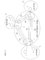
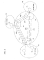
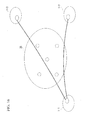
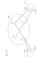
- FIG. 1 is a diagram showing the overall structure of the multi-layer photonic network of these first through fifth preferred embodiments.
- each of these preferred embodiments is a multi-layer photonic network, comprising a plurality of sub-networks 9 through 11 which perform switching and transfer in packet units, optical paths OP1 through OP3 which are O-LSPs which connect these sub-networks 9 through 11, and nodes 1 through 3 which terminate these optical paths OP1 through OP3; and, in addition to the nodes 1 through 3 which are LSCs which are capable of switching in units of optical wavelengths at both ends of the optical wavelength links which consist of the optical paths OP1 through OP3 and the nodes 1 through 3, there are provided respective border routers 4 through 8 as nodes which comprise PSCs which are capable of switching in units of packets.
- the multi-layer photonic network has a two layer construction including the optical paths OP1 through OP3 which are O-LSPs which comprise the nodes 1 through 3 at both their ends, and electrical paths EP1 through EP3 which are E-LSPs which comprise the border routers 4 through 8 at both their ends and include these optical paths OP1 through OP3.
- the distinguishing feature of these first through fifth preferred embodiments of the present invention is that the nodes 1 through 3 establish the paths of the optical paths OP1 through OP3 automatically, according to establishment requests of the electrical paths EP1 through EP3 by the border routers 4 through 8, while taking into consideration path information which includes path cost, resource consumption, and traffic quantity.
- the border routers 4 through 8 calculate the optical paths OP1 through OP3, and the nodes 1 through 3 establish the optical paths OP through OP3 based upon the result of that calculation.
- the border routers 4 through 8 also to serve the function of establishing the optical paths OP1 through OP3. Accordingly, a user who is utilizing the border routers 4 through 8 is able to perform path establishment for the optical paths OP 1 through OP3 which are included in the multi-layer photonic network according to requests. Therefore, along with being able to enhance the convenience for the user, it is not necessary for the network administrator himself to perform path establishment for the optical paths OP1 through OP3.
- the border routers 4 through 8 calculate the optical paths OP1 through OP3 and issue a path establishment request based upon the result of that calculation, and the nodes 1 through 3, after having received this path establishment request, make a decision as to whether or not to establish a path based upon the result of that calculation which is included in this path establishment request; and, if the result is that such path establishment is possible, they establish the path based upon the calculation result; while, if the result is that such path establishment is not possible, they calculate the path for a second time, and establish the optical paths OP1 through OP3.
- the border routers 4 through 8 issue a path establishment request for the optical paths OP1 through OP3, and the nodes 1 through 3 perform path calculation for the optical paths OP1 through OP3 based upon this path establishment request, and make a decision as to whether or not it is possible to establish the optical paths OP1 through OP3; and, as well as communicating the result of this decision to the border routers 4 through 8, the border routers 4 through 8 establish the O-LSP, if such establishment is possible.
- the border routers 4 through 8 issue the path establishment request by selecting, as the one of the nodes 1 through 3 for which establishment of the optical paths OP1 through OP3 is possible, that node i (i is one of 1 through 3) for which the number of hops from that same border router, or the total cost of the link, is the least.
- the border routers 4 through 8 do not perform path calculation for the optical paths OP1 through OP3, and also they are arranged not to perform the establishment of the paths either; but; rather, the path calculation for the optical paths OP1 through OP3 is entrusted to the nodes 1 through 3.
- the load upon the border routers 4 through 8 is alleviated.
- the border routers 4 through 8 are able to perform path establishment requests for the optical paths OP1 through OP3 to the nodes 1 through 3, and, at this time, the border routers 4 through 8 are each able to select the node i for which the convenience is the greatest, from the point of view of this border router itself. Due to this, it is possible to ensure the path and the optical wavelength at high probability.
- the border routers 4 through 8 issue a path establishment request for the optical paths OP1 through OP3, and the nodes 1 through 3 perform path calculation for the optical paths OP1 through OP3 based upon this path establishment request and make a decision as to whether or not it is possible to establish the optical paths OP1 through OP3, and communicate the result of this decision to the border routers 4 through 8; and, if a plurality of communications to the effect that establishment is possible have arrived from a plurality of the nodes 1 through 3, the border routers 4 through 8, from among the nodes 1 through 3 which have issued these communications to the effect that establishment is possible, actually request the establishment of the optical path OPi to that node i from which the communication to the effect that establishment is possible has arrived the most quickly, or to that node i for which the number of hops from this border router itself or the total cost of the link is the least.
- the border routers 4 through 8 do not perform the path calculation for the optical paths OP1 through OP3, and also it is not arranged for them to perform the path establishment; but, rather, the path calculation for the optical paths OP1 through OP3 is entrusted to the nodes 1 through 3. Due to this, the load upon the border routers 4 through 8 is alleviated.
- the border routers 4 through 8 are able to perform path establishment requests for the optical paths OP1 through OP3 to the plurality of nodes 1 through 3, and, at this time, the border routers 4 through 8 are each able to select, from the plurality of the nodes 1 through 3 from which communication to the effect that establishment is possible has been received, that node i for which the convenience is the greatest, from the point of view of this border router itself.
- this node for which the convenience is the greatest for example, there may be taken that node i from which the communication to the effect that establishment is possible has arrived the most quickly, or that node i for which the number of hops from this border router itself or the total cost of the link is the least. Due to this, it is possible to ensure the path and the optical wavelength at high probability.
- the nodes 1 through 3 and the border routers 4 through 8 of these preferred embodiments can be implemented by the use of a computer device, which is an information processing device. That is to say, by installing upon a computer device a program which implements, on this computer device, functions which correspond to the nodes 1 through 3 and to the border routers 4 through 8 which are used in the multi-layer photonic network of these preferred embodiments, and by installing upon the computer device a program which implements a function of automatically establishing the optical paths OP1 through OP3 according to establishment requests of the electrical paths EP1 through EP3, in consideration of path information which includes path cost, resource consumption, and traffic quantity, it is possible to make this computer device serve as a device which corresponds to the nodes 1 through 3 and the border routers 4 through 8 of these preferred embodiments.
- this establishment function by installing upon the computer device a program which implements the function provided to the border routers 4 through 8 of calculating the optical paths OP1 through OP3, and the function provided to the nodes 1 through 3 of establishing the optical paths OP1 through OP3 based upon the calculation result of the calculation function, it is possible to make this computer device serve as a device which corresponds to the nodes 1 through 3 and the border routers 4 through 8 of the first preferred embodiment.
- this establishment function by installing upon the computer device a program which implements the function provided to the border routers 4 through 8 of calculating a path of the optical paths OP through OP3 and of issuing a path establishment request based upon the result of that calculation, and the function provided to the nodes 1 through 3 of, after receiving this path establishment request, based upon that calculation result which is included in the path establishment request, making a decision as to whether or not path establishment is possible, and, if such path establishment is possible, establishing a path based upon that calculation result, while, if such path establishment is not possible, calculating a path for a second time and establishing the optical paths OP1 through OP3, it is possible to make this control device serve as a device which corresponds to the nodes 1 through 3 and the border routers 4 through 8 of the second preferred embodiment.
- this establishment function by installing upon the computer device a program which implements: the function provided to the border routers 4 through 8 of issuing a path establishment request for the optical paths OP1 through OP3; the function provided to the nodes 1 through 3 of performing a calculation of the optical paths OP1 through OP3 based upon this path establishment request and making a decision as to whether or not establishment of the optical paths OP1 through OP3 is possible, and.
- this establishment function by installing upon the computer device a program which implements: the function provided to the border routers 4 through 8 of issuing a path establishment request for the optical paths OP1 through OP3; the function provided to the nodes 1 through 3 of performing a calculation of the optical paths OP1 through OP3 based upon this path establishment request, making a decision as to whether or not establishment of the optical paths OP1 through OP3 is possible, and communicating the result thereof to the border routers 4 through 8; and, as the function of issuing the path establishment request, a function of, if a plurality of communications to the effect that establishment is possible have arrived by the communication function from a plurality of the nodes 1 through 3, actually requesting the establishment of the optical path OPi for the node i, from among those nodes 1 through 3 which have issued these communications to the effect that establishment is possible, for which the communication to the effect that establishment is possible has arrived the most quickly, or for which the number of hops from this border router itself or the total cost of the link is the least;
- each of the nodes 1 through 3 and the border routers 4 through 8 calculating the most suitable path and automatically establishing the O-LSP and the E-LSP, it is possible to implement a multi-layer photonic network and nodes which can be expected to operate efficiently. using a computer device.
- the first preferred embodiment of the present invention will be explained with reference to FIG. 1.
- the reference symbols 1, 2, and 3 denote nodes of the multi-layer photonic network, while the reference symbols 4, 5, 6, 7, and 8 denote border routers of the sub-networks; and OP1, OP2, and OP3 are optical paths (O-LSPs), EP1, EP2 and EP3 are electrical paths, and the reference symbols 9, 10, and 11 denote the sub-networks.
- the electrical path EP 1 is established. for the border router 4 and the border router 5 by using the optical path OP1.
- the electrical path EP2 is established for the border router 6 and the border router 7 by using the optical path OP2.
- the border router 8 requests the establishment of an E-LSP with the border router 7 to the node 1.
- the node 1 since there is no O-LSP between the node 1 and the node 3, while it is possible to establish an E-LSP with the border router 7 via the node 2, it is also possible to establish the electrical path EP3 by newly establishing the optical path OP3 directly with the node 3. The decision as to which of these is the most suitable to be established is made by the node 1.
- FIG. 2 is a diagram for explanation of the O-LSP establishment procedure of this second preferred embodiment of the present invention.
- the reference symbols 12, 13, and 14 denote nodes which can terminate O-LSPs and each of which has both PSC and LSC, while R1 is an O-LSP path designation signal and OP4 is an O-LSP.
- the node 12 If the node 12 has decided to establish an E-LSP which uses the node 14 via the node 13 as the current result of path calculation of the E-LSP, then the node 12 dispatches a signal R1 to the node 13 which designates the use of the optical path OP4 between the node 12 and the node 14, and the node 13 performs establishment of an E-LSP using the optical path OP4.
- FIG. 3 is a diagram for explanation of the O-LSP establishment procedure of this third preferred embodiment of the present invention.
- the reference symbol R2 denotes an O-LSP establishment designation signal. If the node 12 has decided to establish an E-LSP via the node 13 as the result of current path calculation of the E-LSP, then the node 12 dispatches a signal R2 to the node 13 which designates the establishment of the optical path OP4 between the node 12 and the node 14. In the node 13, path calculation is performed for a second time, and the optical path OP4 is established with the node 14 which is considered to be the most suitable one.
- FIG. 4 is a diagram for explanation of the O-LSP establishment procedure of this fourth preferred embodiment of the present invention.
- the reference symbol 15 denotes a node which is capable of terminating an O-LSP and which, just like the other nodes, has both PSC and LSC, while R3 denotes an O-LSP establishment request signal and A3 denotes an O-LSP establishment possible/impossible notification signal.
- the node 12 calculates the path for making the E-LSP, and dispatches the signal R3 which requests the establishment of an O-LSP with the next node to the node 13 which possesses an O-LSP establishment capability.
- the node 13 it is investigated whether or not it is possible to establish the O-LSP, based upon the signal R3, and if it is possible then the O-LSP is established, and a signal A3 is returned to the node 12 with contents which indicate that establishment has been possible; while if the establishment of the O-LSP which has been designated by the signal R3 is not possible, then a signal A3 is returned with contents which indicate that such establishment is not possible.
- the returned signal is inspected, and if the signal A3 from the node 13 is a signal which indicates that establishment is not possible, then the path calculation is performed for a second time, and a signal R3 requesting the establishment of an O-LSP is dispatched to the node 14. If a signal that establishment of an O-LSP is not possible is returned from the node 14, then next an O-LSP establishment request signal is dispatched to the node 15. This operation is repeated until the node 12 is able to make an E-LSP path. It should be understood that the order of the partner nodes to which the node 12 dispatches O-LSP establishment requests is performed in order of the results of path calculation of the E-LSP. or, if an O-LSP is established, in the order of smallest hop number, or in the order of smallest total cost.
- FIG. 5 is a diagram for explanation of the O-LSP establishment procedure of this fifth preferred embodiment of the present invention.
- the reference symbols R41, R42, and R43 denote O-LSP path calculation request signals, while A41, A42, and A43 denote O-LSP path calculation result signals.
- the node 12 dispatches O-LSP path calculation request signals at the same time to all of the nodes which have O-LSP establishment capability at the present time.
- the nodes which have received the O-LSP path calculation request signals perform their respective O-LSP path calculations, and return the results thereof to the node 12 carried in O-LSP path calculation result signals. From among the nodes which have returned contents as their returned O-LSP path calculation result signals which indicate that O-LSP establishment is possible, one or the other of the node which has returned its O-LSP path calculation result signal the most quickly, or the node for which the calculated cost is the least, or the node for which the calculated number of hops is the least, is adopted in the node 12 as the result, and an O-LSP establishment command is issued to its node.
- FIG. 6 is an overall structural view of the multi-layer photonic network according to these preferred embodiments.
- the reference numerals 1A, 2A, and 3A denote nodes of the photonic network, while 4A, 5A, 6A, and 7A denote border routers of sub-networks, 8A, 9A, and 10A denote the sub-networks themselves, OP1, OP2, and OP3 denote optical paths (O-LSPs), and EP1, EP2, and EP3 denote electrical paths (E-LSPs).
- the electrical path EP1 is established for the border router 4A and the border router 5A using the optical path OP1.
- the electrical path EP2 is established for the border router 6A and the border router 7A using the optical path OP1 and the optical path OP2.
- the electrical path EP2 is relayed at the node 2A.
- each comprises the plurality of sub-networks 8A through 10A which perform switching and transfer by packet units, the optical paths OP1 through OP3 which are O-LSPs which connect these sub-networks 8A through 10A, and the nodes 1A through 3A which terminate these optical paths OP1 through OP3; and, at both the ends of the optical wavelength links which are constituted by the optical paths OP through OP3 and the nodes 1A through 3A, in addition to the nodes 1A through 3A which are endowed with the LSC capability of switching in units of optical wavelengths, the border routers 4A through 7A are also respectively provided as nodes which are endowed with the PSC capability of switching in units of packets.
- a node 1A through 3A or a border router 4A through 7A is applied to a multi-layer photonic network of a two layer construction, consisting of the optical paths OP1 through OP3 which are O-LSPs which are provided with the nodes 1A through 3A at both their ends. and the electrical paths EP1 through EP3 which are E-LSPs which are provided with the border routers 4A through 7A at both their ends and include these optical paths OP1 through OP3.
- the characteristic feature of these preferred embodiments is that, when a node 1A through 3A or a border router 4A through 7A is a node 1A through 3A or a border router 4A through 7A which is related to an O-LSP or an E-LSP which has been newly established, this is advertised to all the nodes, only provided that the establishment information for the O-LSP or E-LSP which the node 1A through 3A or the border router 4A through 7A maintains satisfies a specified condition.
- FIG. 7 is a flow chart showing the establishment procedure for an O-LSP or an E-LSP of the sixth preferred embodiment
- the node 1A through 3A or the border router 4A through 7A releases the O-LSP or E-LSP.
- the node 1A through 3A or the border router 4A through 7A newly establishes an O-LSP or E-LSP (in the step 1), and after a predetermined time period has elapsed (in the step 2), then the traffic is observed (in the step 3). If the result of this observation is that no traffic is present (in the step 4), then the newly established O-LSP or E-LSP is released (in the step 5). Furthermore, if the result of the observation in the step 3 is that traffic is present (in the step 4), and if it is possible to shift this traffic to another O-LSP or E-LSP (in the step 6), then the newly established O-LSP or E-LSP is released (in the step 5).
- step 3 if the result of the observation in the step 3 is that traffic is present (in the step 4), and if it is not possible to shift this traffic to another O-LSP or E-LSP (in the step 6), then the establishment of the newly established O-LSP or E-LSP is continued (in the step 7).
- FIG. 8 is a flow chart showing the establishment procedure for an O-LSP or an E-LSP of this seventh preferred embodiment of the present invention.
- node 1A through 3A or the border router 4A through 7A shifts the traffic to a different O-LSP or E-LSP and releases the newly established O-LSP or E-LSP.
- the node 1A through 3A or the border router 4A through 7A newly establishes an O-LSP or an E-LSP (in the step 1), and after a predetermined time period has elapsed (in the step 2), observes the traffic (in the step 3). If the result of this observation is that the traffic is not greater than a threshold value (in the step 4), then the traffic upon the newly established O-LSP or E-LSP is shifted to a different O-LSP or E-LSP (in the step 5), and the newly established O-LSP or E-LSP is released (in the step 6). Furthermore, if the result of the observation in the step 3 is that the traffic is greater than the threshold value (in the step 4), then the establishment of the newly established O-LSP or E-LSP is continued (in the step 7).
- the threshold value which is established in common for the entire network is established according to traffic conditions, but, since the traffic upon the newly established O-LSP or E-LSP is shifted to a different O-LSP or E-LSP if the threshold traffic value is not exceeded, accordingly this threshold value is selected so that the traffic quantity is one which can be easily shifted to another O-LSP or E-LSP at this time.
- FIG. 9 is a flow chart showing the advertisement procedure of the eighth preferred embodiment of the present invention.
- the specified condition is the condition that the O-LSP or the E-LSP which has been newly established by the node 1 A through 3A or the border router 4A through 7A has not been released even after a predetermined time period has elapsed.
- the node 1A through 3A or the border router 4A through 7A newly establishes an O-LSP or an E-LSP (in the step 1), and after a predetermined time period has elapsed (in the step 2), if this O-LSP or E-LSP has not been released (in the step 3), the node 1A through 3A or border router 4A through 7A advertises the establishment information to all the nodes (in the step 4).
- FIG. 10 is a flow chart showing the advertisement procedure of the ninth preferred embodiment of the present invention.
- the specified condition is the condition that an E-LSP has been established whose priority exceeds a threshold value which determines the level of the priority within the priorities which are accorded when E-LSPs are being established, after a predetermined time period has elapsed from the fresh establishment of an O-LSP.
- the node 1A through 3A newly establishes an O-LSP (in the step 1), and after a predetermined time period has elapsed (in the step 2), if an E-LSP of high priority has been established by a border router 4A through 7A (in the step 3), it advertises the establishment information to all the nodes (in the step 4).
- FIG. 11 is a flow chart showing the establishment procedure for an O-LSP of the tenth preferred embodiment of the present invention.
- a node 1A through 3A newly establishes an O-LSP (in the step 1), and after a predetermined time period has elapsed (in the step 2), if an E-LSP of low priority has been established (in the step 3), the traffic upon the E-LSP is shifted to another O-LSP (in the step 4), and the newly established O-LSP is released (in the step 5).
- FIG. 12 is a flow chart showing the establishment request refusal procedure of the eleventh preferred embodiment of the present invention.
- an establishment request for an O-LSP or E-LSP arrives (in the step 1), and if the O-LSP or E-LSP which is the object of this establishment request is an O-LSP or E-LSP which has been newly established but has not been advertised by a node 1A through 3A or a border router 4A through 7A (in the step 2), then this request is refused (in the step 3).
- FIG. 13 is a flow chart showing the establishment procedure for an E-LSP of the twelfth preferred embodiment of the present invention.
- the function of controlling the nodes 1A through 3A and the border routers 4A through 7A of these preferred embodiments of the present invention can be implemented using a computer device, which is an information processing device.
- a computer device which is an information processing device.
- a program which implements upon that computer device the function of controlling the nodes 1A through 3A or the border routers 4A through 7A which are utilized in the multi-layer photonic network of these preferred embodiments
- by implementing a function of, when this itself is the node 1A through 3A or the border router 4A through 7A which is related to a newly established O-LSP or E-LSP advertising to all the nodes the establishment information for the O-LSP or E-LSP which is kept by the node 1A through 3A or the border router 4A through 7A, provided that a specified condition is satisfied, and also a function of, if no traffic is present upon the newly established O-LSP or E-LSP after a predetermined time period has elapsed, or if, even after
- the specified condition is the condition that the newly established O-LSP or E-LSP is not released by the release function even after the predetermined time period has elapsed.
- the specified condition is the condition that an E-LSP has been established of priority which exceeds a threshold value which determines the level of the priority within the priorities which are accorded when establishing E-LSPs after a predetermined time period has elapsed from a newly established O-LSP.
- the node 1A and the node 3A do not advertise the establishment information for the optical path OP3 and the electrical path EP3 to the other nodes, since, if the increased traffic is temporary, the optical path OP3 and the electrical path EP3 may well be released immediately, and the traffic between the border router 6A and the border router 7A may well return to the original electrical path EP2.
- the traffic upon the electrical path EP3 is measured, and, if this traffic has already ceased, the node 1A directly releases the electrical path EP3 and the optical path OP3. If this traffic is still present, it is investigated as to whether or not the quantity of this traffic is such as to be able to be shifted to the original electrical path EP2, and if it is of such a quantity as can be shifted, then this traffic is shifted to the electrical path EP2, and the electrical path EP3 and the optical path OP3 are released.
- the optical path OP2 and the electrical path EP3 are taken to be paths which are to be continued over a long time period, and their establishment information is advertised to all the nodes.
- a threshold value is set for the traffic quantity upon the newly established optical path OP3 and the electrical path EP3, and the traffic is measured after a fixed time period; and if this traffic is equal to or less than the threshold value, then the traffic is returned to the original electrical path EP2, and the electrical path EP3 and the optical path OP3 are released; whereas, if this traffic is equal to or greater than the threshold value, then the optical path OP3 and the electrical path EP3 are taken as paths which are to be continued over a long time period, and their establishment information is advertised to all the nodes.
- a priority is provided for the E-LSPs, and, if the priority of the E-LSP which uses the electrical path EP3 is low, then the traffic quantity is measured after a fixed time period, and a decision is made as to whether or not it can be shifted to the original electrical path EP2. However, if the priority of the E-LSP which uses the electrical path EP3 is high, then the optical path OP3 and the electrical path EP3 are taken as paths which are to be continued over a long time period, and their establishment information is advertised to all the nodes.
- optical path OP3 and the electrical path EP3 are established, they are not advertised to all the nodes, if the node 1A has requested from the node 3A the establishment of a new E-LSP of high priority using the optical path OP3, new E-LSP establishment requests are refused.
- the reason is that, when the advertisement for the optical path OP3 and the electrical path EP3 is withheld since they are temporary ones, if establishing a new E-LSP, it becomes impossible to release the optical path OP3 even if the traffic upon the original electrical path EP3 ceases.
- optical path OP3 is a temporary one and accordingly its advertisement has been withheld, then, when establishing a new E-LSP which is to continue for a long time period, a requirement arises to re-advertise the existence of the optical path OP3.
- this type of re-advertisement procedure is not assumed, and since furthermore the procedures would be made more troublesome by additionally providing the function of performing this type of re-advertisement procedure, accordingly in this preferred embodiment it is arranged to refuse establishment requests for new E-LSPs of high priority to the optical path OP3 for which advertisement has not been performed.
- FIG. 14 is a diagram showing an example of a physical network structure which consists of physical optical transmission lines and nodes.
- FIG. 15 is a diagram showing an example of a theoretical optical wavelength network structure which utilizes the physical structure of FIG. 14.
- FIG. 16 is a diagram showing an example of the structure of an O-LSP.
- FIG. 17 is a diagram showing an example of a photonic network structure for explanation of a preferred embodiment of O-LSP path calculation.
- FIG. 18 is a diagram showing an example of a plurality of connection structures between sub-networks and a photonic network.
- FIG. 14 is a diagram showing an example of a physical network structure which consists of physical optical transmission lines and nodes.
- FIG. 15 is a diagram showing an example of a theoretical optical wavelength network structure which utilizes the physical structure of FIG. 14.
- FIG. 16 is a diagram showing an example of the structure of an O-LSP.
- FIG. 17 is a diagram showing an example of a photonic network structure for explanation of a preferred embodiment
- FIG. 19 is a diagram showing an example of a signal sequence when establishing an O-LSP between nodes.
- FIG. 20 is a diagram showing an example of a structure of a relay node of the present invention.
- FIG. 21 is a diagram showing examples of structures of an O-LSP and an E-LSP, when a relay router is used.
- the multi-layer photonic network of these fourteenth through eighteenth preferred embodiments of the present invention comprises a plurality of sub-networks 1-1 through 1-4 which perform switching and transfer in units of packets, and a photonic network 2B which is connected in common to this plurality of sub-networks 1-1 through 1-4, and is made up by optical transmission lines, nodes 2-1 through 2-4 which terminate these optical transmission lines, and an optical relay router 2-5; and the multi-layer photonic network is characterized in that LSC for performing switching in units of optical wavelengths or PSC for performing switching in units of packets are provided at the end points of optical wavelength links which mutually connect between the nodes 2-1 through 2-4 and the optical relay router 2-5, and between the nodes 2-1 through 2-4 and border routers 1-1R through 1-4R in the sub-networks 1-1 through 1-4, and by comprising optical paths both ends of which, as shown in FIG.
- each of the nodes 2-1 through 2-4, the optical relay router 2-5, and the border routers 1-1R through 1-4R is endowed with both LSC and PSC.
- calculating devices which calculate the optical paths as objects of optical wavelength links to which LSC is provided at least at their one ends, and devices which calculate the electrical paths based upon the optical paths which have been calculated by the above calculating devices; however, these devices are omitted from the drawing.
- These devices may be provided to each of the nodes 2-1 through 2-4, the optical relay router 2-5, and the border routers 1-1R through 1-4R; or, alternatively, a single one thereof may be provided for the entire network.
- an advertising device which, when establishment of the optical paths or the electrical paths has been performed based upon the results of calculation by the calculation devices, advertises the establishment information therefor to the nodes 2-1 through 2-4, the optical relay router 2-5, and the border routers 1-1R through 1-4R. It would be acceptable to make this advertising device and the calculation devices as a single device.
- a plurality of border routers 1-1R1, 1-1R2, 1-2R1, and 1-2R2 which connect to the photonic network 2B are provided within a single one of the sub-networks 1-1 or 1-2, and it is also possible to have a plurality of connection paths between a single one of the sub-networks 1-1 or 1-2 and the photonic network 2B.
- the nodes 2-1 through 2-4, the optical relay router 2-5, and the border routers 1-1R through 1-4R comprise devices which change and release the establishment of the optical paths or the electrical paths in an autonomous and distributed manner based upon a policy which includes hop number, traffic conditions, and network cost. These devices which change and release such establishment may be structured as the same devices as the calculation devices or the advertising devices.
- an optical relay router 2-5 which comprises a router 5-1 which is a PSC and a photonic cross connect 5-2 which is an LSC, and, in this optical relay router 2-5, one portion of the input and output ports of the photonic cross connect 5-2 is connected to the router 5-1.
- the device of these preferred embodiments can be implemented using a computer device, which is an information processing device.
- a computer device which is an information processing device.
- a program which implements, as a function which corresponds to a device which is applied to the multi-layer photonic network of these preferred embodiments, a function of calculating a path of the optical path, taking as object an optical wavelength link which is provided with LSC at least at one of its ends, and a function of calculating a path of the electrical path based upon the optical path which has been calculated by this calculation function, it is possible to make this computer device serve as a device which corresponds to the calculation device of these preferred embodiments.
- this computer device serves as a device which corresponds to the advertisement device of these preferred embodiments.
- the fourteenth preferred embodiment of the present invention will now be explained with reference to FIGS. 14 through 16.
- the reference symbols 1-1, 1-2, 1-3, and 1-4 denote sub-network groups, while 1-1R, 1-2R, 1-3R, and 1-4R denote border routers within the sub-networks which are points where these sub-networks are connected to the photonic network.
- the reference symbol 2B denotes the photonic network, while 2-1, 2-2, 2-3, 2-4, and 2-5 are nodes which are capable of exchange by units of optical wavelengths.
- connection points with the photonic network 2B at the border routers of the sub-network are defined as PSCs which are capable of exchange by units of packets, while the connection points between the nodes in the photonic network are defined as LSPs which are capable of exchange by units of optical wavelengths.
- PSCs connection points with the photonic network 2B at the border routers of the sub-network
- LSPs connection points between the nodes in the photonic network
- optical wavelength links are established so that all of the nodes can be connected together. Furthermore, optical wavelength links are established so that all of the sub-networks are connected to the photonic network.
- O-LSPs are established so that the sub-networks are connected in the order from the highest traffic between the sub-networks. For example, if traffic is present between the sub-network 1-1 and the sub-network 1-2, the border router 1-1R of the sub-network 1-1 requests to the node 2-1 of the photonic network the establishment of an O-LSP between the sub-network 1-1 and the sub-network 1-2. The node 2-1 calculates the route for which the number of hops is the least, and establishes an O-LSP between the sub-network 1-1 and the sub-network 1-2 using an optical wavelength link up to the node 2-2.
- connection from the node 2-1 to the node 2-2 via the node 2-5 might also be considered as a candidate
- the route of direct connection from the node 2-1 to the node 2-2 is selected in the calculation, because it requires only one hop.
- the establishment of an O-LSP with the sub-network 1-3 is requested to the node 2-1. Since it has no direct optical wavelength link with the node 2-3 which is connected to the sub-network 1-3, the node 2-1 uses an optical wavelength link with the relay node 2-5, and also the relay node 2-5 uses an optical wavelength link with the node 2-3, and the node 2-3 uses an optical wavelength link with the sub-network 1-3, and thereby the O-LSP between the sub-network 1-1 and the sub-network 1-3 is established.
- the sub-network side requires the establishment of an E-LSP due to traffic on the sub-network side with a cooperating sub-network, its establishment is requested to the photonic network, and the photonic network diverts an already existing O-LSP or newly establishes an O-LSP, thus satisfying the E-LSP establishment request from the sub-network, and moreover calculates the path over the photonic network for which the efficiency is the highest.
- FIG. 16 shows an example of the structure of an O-LSP which has been set up in this manner.
- the E-LSP is made using these O-LSPs, no change is made for the E-LSP, even if for convenience there is some change in the path of the O-LSPs due to the occurrence of congestion or trouble upon the photonic network.
- the E-LSP it is possible to consider the E-LSP as a single link which is directly connected between the border routers in the sub-network, without any relation to the path of the O-LSPs.
- the establishment information for the above described O-LSP is made known to all the nodes upon the photonic network, and each of the nodes maintains all the link information for the photonic network.
- the information for the O-LSPs and E-LSPs which already exist is referred to.
- the fifteenth preferred embodiment of the present invention will now be explained with reference to FIG. 17.
- the reference symbols L1 through L8 denote O-LSPs which are connected between the nodes, while OP1 and OP2 respectively connect together the sub-network 1-1 and the sub-network 1-2, and the sub-network 1-1 and the sub-network 1-3.
- the node 2-2 extracts from a link establishment data base which is maintained by this node the establishment information for the O-LSP and a point at which PSC is available, and calculates the most efficient path from the border router 1-2R to the border router 1-3R.
- the calculation is performed for the cases of establishing the path L2 - L5 - L3, or the path L2 - L6 - L8 - L3, or the path L2 - L4 - L7 - L8 - L3, or a direct O-LSP between the nodes 2-2 and 2-3, or the like, in consideration of factors such as the number of hops, the traffic conditions, the network cost, and the like. Which factor is regarded as of what importance is decided according to the policy of the network.
- the node 2-2 makes up the optical path OP3 from the paths which, from the result of this calculation, it has decided have the greatest efficiency, and requests its establishment to the relevant nodes.
- the link establishment information related to the optical path OP3 is advertised to all the nodes upon the photonic network 2B.
- the sixteenth preferred embodiment of the present invention will now be explained with reference to FIG. 18.
- the sub-network 1-1 comprises the border routers 1-1R1 and 1-1R2, each of which is connected to the node 2-1 of the photonic network.
- the sub-network 1-2 comprises the border routers 1-2R1 and 1-2R2, which are connected to the nodes 2-2 and 2-3 of the photonic network respectively.
- the border router 1-1R requests (S1) the node 2-1 to establish an O-LSP having a bandwidth of 10M bits/sec with the border router 1-3R.
- the node 2-1 calculates the route for this O-LSP for which the efficiency is the highest, and ensures (S2) a bandwidth of 10M bits/sec by performing negotiation with the relay node 2-5 and establishing or using an optical wavelength link with that node 2-5.
- the relay node 2-5 ensures a bandwidth of 10M bits/sec (S3) by establishing or using an optical wavelength link with the node 2-3.
- the node 2-3 then ensures (S4) a bandwidth of 10M bits/sec with the border router 1-3R.
- the O-LSP of 10M bits/sec between the border router 1-1R and the border router 2-3R is completed. If partway through it has not been possible to ensure the 10M bits/sec which has been requested, then the route for the O-LSP is calculated again, and another route is sought for.
- the node 2-1 which has received an request from the border router 1-1R for the establishment of an O-LSP could also designate the entire O-LSP route up to the destination sub-network and could request the establishment of an optical wavelength link to the next node; or, without designating the O-LSP route as far as the destination sub-network, it could entrust this task to the next node or to a subsequent node. If, in heavy traffic conditions, it is desired to specify exactly which route is to be taken over the photonic network, or if it is desired to practice a method of use such as a conventional common carrier leased line or the like, then the O-LSP is established according to the former request. In this type of case, change of the O-LSP due to traffic fluctuations is not frequently accomplished.
- the O-LSP is established without designating its route, then it is possible to use the most efficient O-LSP route for the convenience of the photonic network, and it is also possible to change the route of the O-LSP with traffic fluctuations or the like.
- Autonomous and distributed control is provided by each node performing establishment of O-LSPs and negotiation of their use with subsequent nodes. Furthermore, in addition to performing the establishment or the use of an O-LSP with the next node upon a request from another node, in a case such as, for example, when the usage ratio upon some route becomes high and congestion occurs, or if it is not possible to perform communication due to malfunction of the transmission line or the like, the provision of an E-LSP is ensured by establishing or using an O-LSP upon another route, according to a decision made by the node itself.
- the eighteenth preferred embodiment of the present invention will now be explained with reference to FIGS. 20 and 21.
- the reference symbol 5-1 denotes a photonic cross connect which switches in units of optical wavelengths
- the reference symbol 5-2 is a packet router which performs exchange in units of packets
- the reference symbols 5-3 and 5-4 are input ports connected to other nodes, at which a plurality of optical wavelengths are bundled.
- the reference symbols 5-5 and 5-6 are output ports connected to other nodes, at which the plurality of optical wavelengths are re-bundled.
- the bundled optical wavelength input is decomposed into each wavelength, enters into the photonic cross connect, and is converted into the optical wavelengths for and is outputted at the output ports which are set up for each optical wavelength.
- the relay node according to the present invention is not only endowed with an LSP function, but also is endowed with a PSC function; and, while packets are transmitted from another node to this relay node by using a single O-LSP, they can be temporarily decomposed into packet units in this relay node, can be routed to the destination of each packet, and then can be again put onto their respective O-LSPs and transmitted.
- FIG. 21 shows an example of a structure for O-LSPs and E-LSPs when the relay router of this preferred embodiment is utilized.
- the reference symbols OP4, OP5, and OP6 denote O-LSPs, while EP1 and EP2 are E-LSPs.
- OP4 is set up from the border router 1-1R to the relay node 2-5
- OP5 is set up from the relay node 2-5 to the border router 1-3R
- OP6 is set up from the relay node 2-5 to the border router 1-4R
- EP1 is set up between the border router 1-1R and the border router 1-3R using OP4 and OP5
- EP2 is set up between the border router 1-1R and the border router 1-4R using OP4 and OP6.
- the O-LSP of the highest efficiency is always set up, and there is the beneficial point that it is possible to maintain the E-LSP structure which is requested by the user.
- the beneficial aspect that it is possible easily to respond to congestion, and, furthermore, by providing a plurality of border routers, there is the beneficial point that the reliability is enhanced.
- there is the beneficial aspect that it is not necessary for the network maintenance personnel or the like to perform manual intervention, since the most suitable O-LSPs are set up by the nodes within the photonic network making decisions autonomously.
- FIG. 22 shows an example of the structure of a network system according to the nineteenth through the twenty-third preferred embodiments of the present invention.
- These nineteenth through twenty-third preferred embodiments premise a multi-layer network which comprises a packet network 7C (packet link: E-LSP) which is made up from optical path links by packet switches 2C (packet switching capability: PSC) and optical paths 4C (4C'), and a photonic network 8C (optical wavelength link: O-LSP) which comprises optical switches 3C (optical wavelength switching capability: LSC) and fiber links by fibers 5C.
- E-LSP packet link
- PSC packet switching capability
- 4C optical paths 4C
- O-LSP optical wavelength link
- LSC optical wavelength switching capability
- the packet network 7C is a packet cell switching network, and in the case of the Internet is an IP network.
- the reference symbol 4C in the drawing denotes an optical path (link) which is a path along which signals are actually transferred, while the symbol 4C denotes a conceptual link which is an optical path as seen from the point of view of the packet network.
- the reference symbol 6C denotes traffic.
- This type of multi-layer network can be made with photonic routers 1C (1C-1 through 1C-4) which are implemented in an integrated manner from the packet switches 2C and the optical switches 3C.
- This photonic router 1C as shown in FIG. 23, comprises a packet switch 2C, an optical switch 3C, and an integrated control device (a GMPLS controller) 10C which manages them in an integrated manner. Control signals are mutually exchanged between the integrated control devices 10C for the various photonic routers 1C via control signal lines.
- a GMPLS controller integrated control device
- 128 x 128 switching is used in the optical switch 3C, and it has a capability of inputting and outputting four fiber links upon which the optical path is 32 wavelength multiplexed.
- the transmission rate of each of the optical paths is 2.5G bits/sec, and they are terminated by SONET OC-48 interfaces.
- the control signal lines have a transmission rate of 155M bits/sec, and are made with SONET OC-3 lines; and the control signals which are propagated over them may, for example, be OSPF/IS-IS protocol packets for acquiring the network topology of the photonic router network, or may be RSVP-TE/CR-LDP protocol packets for establishing and releasing the optical paths which are to be established between packet switching devices; or they may be LMP (Link Management Protocol) packets which perform malfunction supervision for the fiber links.
- OSPF/IS-IS protocol packets for acquiring the network topology of the photonic router network
- RSVP-TE/CR-LDP protocol packets for establishing and releasing the optical paths which are to be established between packet switching devices
- LMP Link Management Protocol
- the integrated control device 10C for each of the photonic routers 1C implements function sections for processing these control signal protocols, and comprises a routing processing function (OSPF/IS-IS protocol processing function) section 20C, an optical path establishment processing function (RSPV-TE/CR-LDP protocol processing function) section 30C, and a malfunction management function (LMP protocol processing function) section 40C for the optical fibers and the links to the adjacent nodes.
- OSPF/IS-IS protocol processing function OSPF/IS-IS protocol processing function
- RSPV-TE/CR-LDP protocol processing function optical path establishment processing function
- LMP protocol processing function malfunction management function
- the routing processing function section 20C comprises a flooding section 21C, a link state data base (DB) 22C, an extension link state data base (DB) 23C, a switching capability supervision section 24C, a path calculation section 25C, and a next hop data base (DB) 26C.
- the flooding section 21C is a function section which communicates to the adjacent nodes the link state information which it has collected from its own node and from other nodes.
- the link state data base 22C and the extension link state data base 23C are data bases which retain the link information which has been collected from other nodes, and the optical path link state information is stored in the link state data base 22C, while the fiber link state information is stored in the extension link state data base 23C.
- optical path link state information which is stored in the link state data base 22C is, in concrete terms, vacancy information and cost information for the optical path links which are connected to two packet switches and which are also accommodated to fiber links.
- the fiber link state information which is stored in the extension link state data base 23C is, in concrete terms, vacancy information and cost information for the fiber links which are connected to two optical switches.
- the switching capability supervision section 24C is a function section which supervises the switching state of its own node. For example if, in the switching of its own node, not only is there a function of establishing an optical path into the optical switch 3C, but also a capacity is present to accommodate an optical path into the packet switch 2C, then it advertises to the other nodes the fact that a switching capability for packet switching / optical switching is available.
- the path calculation section 25C performs calculation for optical paths (O-LSPs) established from the link state data base 22C, and for theoretical paths (LSPs) or packet transfer paths which are switched by the packet switch 2C.
- O-LSPs optical paths
- LSPs theoretical paths
- packet transfer paths which are switched by the packet switch 2C.
- the next hop data base 26C is a data base in which the results of path calculation are stored, and it temporarily stores information as to which interface the packets which arrive at each node should be used to transfer the packets.
- the optical path establishment management function section 30C comprises a path data base (DB) 31 C in which optical path information is stored, and a path establishment and deletion function section 32C which performs establishment and deletion of optical paths.
- DB path data base
- 32C path establishment and deletion function section
- the link malfunction management function section 40C comprises a link and adjacent node state data base (DB) 41C which maintains state information for the optical fibers and the adjacent nodes, and a supervisory signal processing function section 42C which performs supervision of the advertisement information from the other nodes and detection of link malfunctions and the like.
- DB link and adjacent node state data base
- the respective link cost is defined by the previously described routing processing function section 20C.
- the routing processing function section 20C defines both costs for the fiber links which connect two of the optical switches, and also costs for the optical path links which connect two of the packet switches and which are moreover accommodated in the fiber links.
- the costs of the optical paths which are accommodated in the fiber links, and the transfer cost of the packet traffic which is accommodated in the optical path links, are calculated from these costs in accordance with a Dijkstra algorithm, and the packet traffic is subjected to transfer processing by the routes for which the totals of the costs between the start points and the end points of the traffic are minimum, while the optical paths are established upon the routes for which the costs over the intervals between the start points and the end points which are established are minimum.
- the cost of the fiber links may be allocated using values such as the lengths of the various fiber intervals, the reciprocals of the capacities of the fiber links (the reciprocals of the numbers of optical paths which can be accommodated in them), or the expenditure which was actually required for their construction.
- the cost of the optical path links which are established between two packet switches may be allocated using values such as the reciprocal of the transmission rate of each optical path, or the sum of the fiber link costs which are accommodated in the optical paths multiplied by some constant value. In this manner, it is usual for the costs of the fiber links and of the optical path links upon the same path to be defined as having different values.
- FIG. 24 is a diagram for explanation of this nineteenth preferred embodiment of the present invention
- FIG. 25 is a flow chart for this nineteenth preferred embodiment.
- OLSP #1 is an optical path which connects together node #1 and node #4;
- OLSP #2 is an optical path which connects together node #4 and node #5;
- OLSP #3 is an optical path which connects together node #5 and node #3;
- OLSP #4 is an optical path which connects together node #1 and node #2; and
- OLSP #5 is an optical path which connects together node #1 and node #3.
- optical path links are "10" for OLSP #1 through OLSP #4, and "40" for OLSP #5.
- the costs of the fiber links between node #1 and node #2, between node #2 and node #3, between node #1 and node #4, and between node #4 and node #5 are each "50", while the cost of the fiber link between node #5 and node #3 is "20".
- the route is searched out for which the optical path link cost of the already established optical paths which connect between node #1 and node #3 is the smallest (in the step S11). If there is no route to the final point node (node #3) by an already established optical path, in other words if the cost up to the end point node is infinitely great, then the flow of control is transferred to the step S14. If a route does exist, then the packet traffic is accommodated in the optical path upon this searched out route, and packet transfer is performed (in the step S13).
- the route from node #1 to node #3 for which the cost is minimum, including the fiber links, is searched for (in the step S14). If a route is found (in the step S15), then an optical path is newly established for this route, and the packet traffic is accommodated in this newly established path and packet transfer is performed (in the step S16).
- FIG. 26 is a diagram for explanation of this twentieth preferred embodiment of the present invention
- FIG. 27 is a flow chart for this twentieth preferred embodiment.
- the route search is performed with consideration being given to a limit upon the number of O-LSP hops.
- the shortest path from the point of view of the packet network 7 (the path for which the optical path link cost is the minimum) is searched out. If it is possible to arrive at the destination by an optical path which is already established and for which the number of hops is within the specified limit number, then the packet traffic is accommodated in this path, while if it is not possible, then an optical path is newly established.
- the optical path link path of the minimum cost from node #1 to node #3 is searched out, since the route node #1 - node #4 - node #5 - node #3 exceeds the specified limit number of O-LSP hops, the accommodation of packet traffic therein is forbidden, and the route node #1 - node #3 (via node #2) acquires rank 1.
- the packet traffic is accordingly accommodated in the optical path of this rank 1 route, and a new optical path is established when the vacant capacity of this optical path has become insufficient.
- the flow chart for this twentieth preferred embodiment of the present invention shown in FIG. 27 is almost the same as the flow chart for the nineteenth preferred embodiment shown in FIG. 25 (the steps S1 through S17), except for the point that it differs from the nineteenth preferred embodiment in that, in the decisions made in the steps S22 and the steps S25 relating to the result of route searching, if the number of O-LSP hops in the searched out route exceeds the specified limit number. this case is handled as though it was impossible to reach the destination with an already established optical path.
- FIG. 28 is a drawing for explanation of this twenty-first preferred embodiment of the present invention
- FIG. 29 is a flow chart for this twenty-first preferred embodiment.
- this twenty-first preferred embodiment of the present invention when a request occurs for the accommodation of packet traffic between specified grounds, first the shortest path from the point of view of the photonic network 8C (the path for which the fiber link cost is the minimum) is searched out. This point differs from the case of the nineteenth preferred embodiment, in which it was from the point of view of the packet network 7C that the shortest path (the minimum optical path link cost path) was searched out. If it is not possible to arrive at the destination by an optical path which is already established upon this path, then for the first time an optical path is newly established.
- the route is searched out for which the fiber link cost of the already established optical paths which connect between node #1 and node #3 is the smallest (in the step S31). If there is no route to the final point node (node #3) by an already established fiber, in other words if the fiber link cost up to the end point node is infinitely great, then the flow of control is transferred to the step S36.
- a route is searched for including also the already established optical path links (in the step S36). If the result is that it is not possible to arrive at the final node (the step S37), then the flow of control is transferred to the step S39. If a route does exist which is capable of arriving at the final node, then packet transfer is performed upon this searched out route (in the step S38). When doing this, if there is an interval upon the searched out route in which there is insufficient optical path, then an optical path is newly established for this interval. If it is not possible to arrive at the final point by any route, then the transfer of the packets is blocked or the packets are discarded (in the step S39).
- FIG. 30 is a diagram for explanation of this twenty-second preferred embodiment of the present invention
- FIG. 31 is a flow chart for this twenty-second preferred embodiment.
- the shortest path from the point of view of the photonic network 8C (the path for which the fiber link cost is the minimum) is searched out. If it is possible to reach the destination upon an optical path which is already established and for which the number of hops is within a specified limit value, then the packet traffic is accommodated in this already established optical path upon this path, while if it is not possible, then an optical path is newly established.
- the flow chart for this twenty-second preferred embodiment of the present invention shown in FIG. 31 is almost the same as the flow chart for the twenty-first preferred embodiment shown in FIG. 29 (the steps S31 through S39), except for the point that it differs from the twenty-first preferred embodiment in that, in the decision made in the step S43 as to whether or not an optical path exists which corresponds to the searched out route, consideration is given to a limit upon the number of O-LSP hops. Furthermore there is the point of difference that, in the decision made in the step S47, if the route which was found in the step S46 has a number of O-LSP hops which exceeds the limit value, then it is determined that there is no route in which the packet traffic can be accommodated.
- FIG. 32 is a diagram for explanation of this twenty-third preferred embodiment of the present invention
- FIG. 33 is a flow chart for this twenty-third preferred embodiment.
- a route which links node #1 and node #3 is searched out, including a cut through for node #2, for which the fiber link cost is minimum (in the step S51).
- step S52 If there is no route to the final node (node #3) by a fiber link, in other words if the cost to the final node is infinitely great (the step S52), then the flow of control is transferred to the step S54. If a route does exist, then an optical path is newly established in the fiber link of this found route (rank 1 of FIG. 32), and the packet traffic is accommodated therein and packets are transferred (in the step S53).
- a route from node #1 to node #3 is searched out for which the cost should be minimum, including already established optical path links (in the step S54). During this search, consideration is given to a limit value upon the number of O-LSP hops, if necessary. If a route which arrives at node #3 is found (the step S55), then packets are transferred upon this route (the step S56) (at this time, node #2 is cut through). If no route is found which arrives at the final point node (node #3), even including already established optical path links, then the transfer of packets is blocked or the packets are discarded (in the step S57).
- the difference from the nineteenth through the twenty-second preferred embodiments described above is that the probability is high that the path in which the packet traffic is accommodated coincides with the shortest path upon the fiber links.
- the case is also permitted in which the limit value upon the O-LSP hop number which is imposed in the step S55 becomes other than unity.
- the combination could be applied of using the twenty-third preferred embodiment of the present invention for high priority class traffic, while using the nineteenth preferred embodiment for low priority class traffic.
- FIG. 34 is a diagram showing the overall structure of the multi-layer photonic network according to this twenty-fourth preferred embodiment.
- This twenty-fourth preferred embodiment is a multi-layer photonic network 1D having a two layer construction, consisting of O-LSPs which are provided with LSP at both their ends, and E-LSPs which are provided with PSC at both their ends and include these O-LSPs, and it comprises a plurality of electrical packet switching sub-networks 2 through 7 (hereinafter these will simply be termed "sub-networks") which perform switching and transfer by packet units, O-LSPs which are connected to these sub-networks 2D through 7D, and packet routers 101 through 107 and border routers 201, 301, 401, 501, 601, and 701 which are nodes which terminate these O-LSPs; and LSC which are capable of switching in units of optical wavelengths and PSC which are capable of switching in units of packets are respectively provided at both ends of the optical wavelength links which are made up from the O-LSPs and the packet routers 101 through 107 and the border routers 201, 301, 401,
- the particular characteristic of this twenty-fourth preferred embodiment of the present invention lies in the fact that the packet routers 101 through 107, as shown in FIG. 38, perform rearrangement of all the E-LSPs in response to detection of congestion upon any of the O-LSPs.
- the packet routers 101 through 107 also conjointly perform rearrangement of the O-LSPs along with the rearrangement of all the E-LSPs.
- the packet routers 101 through 107 decide whether or not it is possible to newly structure by a single hop the O-LSP with which the E-LSP for which the bandwidth used is the widest, or the number of hops is the greatest, or the path cost is the highest, is made, and if such new structuring is possible, they newly structure the O-LSP.
- the packet routers 101 through 107 may perform rearrangement of the O-LSPs a plurality of times virtually, and may then actually execute the rearrangement of the O-LSPs for which, from among these results of rearrangement a plurality of times, the path cost is the minimum. Furthermore, as shown in FIG. 39, it is possible to limit the number of times or the time period that this virtual rearrangement of the O-LSPs is performed. Yet further, as shown in FIG. 39, the packet routers 101 through 107 may perform rearrangement of the O-LSPs virtually by cut and try, and then may actually rearrange the O-LSPs according to the order of the cut and try which was performed virtually.
- release of the O-LSP is executed, provided that it has been confirmed that the change over to another O-LSP of the E-LSP accommodated in the O-LSP is included is already completed, that the connection of all the routers is ensured even if the O-LSP is released, and that congestion upon another O-LSP will not occur even if the O-LSP is released.
- a new O-LSP is made only provided that it is not possible to make it in an already established O-LSP.
- an E-LSP and an O-LSP may be newly established or may be rearranged, according to a predetermined policy which is designated by a policy selector.
- the policies may include a policy #1, with regard to a request for making a new E-LSP, of: making a decision whether or not it is possible to accommodate the E-LSP in an already established O-LSP of a single hop; if it can be thus accommodated, thus accommodating it; if it cannot be thus accommodated in the already established O-LSP of a single hop, making a decision whether or not it is possible to accommodate the E-LSP in an already established O-LSP of a number of hops less than or equal to a predetermined hop number; if it can be thus accommodated, thus accommodating it; if it cannot be thus accommodated in the already established O-LSP of a number of hops less than or equal to a predetermined hop number, making a decision as to whether or not it is possible to make a newly established O-LSP of a single hop; and, if one can be thus made, accommodating the E-LSP in the newly established O-LSP.
- a policy #1 with regard to a request for making a
- the policies may include a policy #2, with regard to a request for making a new E-LSP, of: making a decision whether or not it is possible to accommodate the E-LSP in an already established O-LSP of a single hop; if it can be thus accommodated, thus accommodating it; if it cannot be thus accommodated in the already established O-LSP of a single hop, making a decision as to whether or not it is possible to make a newly established O-LSP of a single hop; if one can be thus made, accommodating the E-LSP in the newly established O-LSP; if the newly established O-LSP cannot be made, making a decision as to whether or not it is possible to accommodate the E-LSP in an already established O-LSP of a number of hops less than or equal to a predetermined hop number; and, if it can be thus accommodated, thus accommodating it.
- a policy #2 with regard to a request for making a new E-LSP, of: making a decision whether or not it is possible to accommodate
- the policies may include a policy #3, with regard to a request for making a new E-LSP, of: making a decision whether or not it is possible to make a newly established O-LSP which accommodates the E-LSP with a single hop; if it is possible to make one, newly establishing the O-LSP and accommodating it therein; if it is not possible to make one, making a decision as to whether or not it is possible to accommodate the E-LSP in an already established O-LSP of a single hop; if it can be thus accommodated, accommodating the E-LSP in the already established O-LSP; if it cannot be accommodated in the already established O-LSP, making a decision as to whether or not it is possible to accommodate the E-LSP in an already established O-LSP of a number of hops less than or equal to a predetermined hop number; and, if it can be thus accommodated, thus accommodating it.
- a policy #3 with regard to a request for making a new E-LSP, of: making
- the policies may include a policy #4, with regard to a request for making a new E-LSP, of: making a decision as to whether or not the E-LSP can be accommodated by making a single newly established O-LSP of a number of hops less than or equal to a predetermined hop number; if it can thus be accommodated, accommodating the E-LSP in the newly established O-LSP; if, at this time, a plurality of candidates for the newly established O-LSP are available, selecting from among the candidates the one whose path cost is the minimum after accommodation of the E-LSP; if it is not possible to accommodate the E-LSP in a single newly established O-LSP, making a decision as to whether or not it is possible to make a number M of newly established O-LSPs of a number of hops less than or equal to a predetermined hop number; and, if they can be made, accommodating the E-LSP by distributing it among the number M of newly established O-LSPs.
- a policy #4 with
- the packet routers 101 through 107 may perform rearrangement with the exception of E-LSPs of the already established bandwidth reservation type.
- the multi-layer photonic network of this twenty-fourth preferred embodiment can be implemented by the use of a computer device, which is an information processing device. That is to say, by installing upon a computer device a program which implements, on this computer device, functions which correspond to the packet routers 101 through 107 which are used in the multi-layer photonic network of this preferred embodiment, and by installing upon the computer device a program which implements a function of performing rearrangement of all the E-LSPs in response to detection of congestion upon any one of the O-LSPs, it is possible to make this computer device serve as a device which corresponds to the packet routers 101 through 107 of this preferred embodiment.
- the program of this twenty-fourth preferred embodiment may implement, as the function of performing rearrangement, a function of conjointly performing rearrangement of the O-LSPs along with the rearrangement of all the E-LSPs.
- a rearrangement simulation function of performing rearrangement of the O-LSPs a plurality of times virtually a function of actually executing the rearrangement of the O-LSPs for which, from among these results of rearrangement by this rearrangement simulation function a plurality of times, the path cost is the minimum.
- the rearrangement simulation function a function of limiting the number of times or the time period that this virtual rearrangement of the O-LSPs is performed.
- rearrangement simulation function a function of performing rearrangement of the O-LSPs virtually by cut and try, and, as the function of actual execution, a function of actually rearranging the O-LSPs according to the order of the cut and try which was virtually performed.
- an O-LSP for which the usage ratio is equal to or below the threshold value there may be implemented a function of executing release of the O-LSP, provided that it has been confirmed that the change over to another O-LSP of the E-LSP in which the O-LSP is included is already completed, that the connection of all the routers is ensured even if the O-LSP is released, and that congestion upon another O-LSP will not occur even if the O-LSP is released.
- a function may be implemented of making a new O-LSP, only provided that it is not possible to make it in already established O-LSP.
- a function may be implemented of newly establishing or rearranging an E-LSP or an O-LSP, according to a predetermined policy.
- the policy may include a policy #1, with regard to a request for making a new E-LSP, of: making a decision whether or not it is possible to accommodate the E-LSP in an already established O-LSP of a single hop; if it can be thus accommodated, thus accommodating it; if it cannot be thus accommodated in the already established O-LSP of a single hop, making a decision whether or not it is possible to accommodate the E-LSP in an already established O-LSP of a number of hops less than or equal to a predetermined hop number; if it can be thus accommodated, thus accommodating it; if it cannot be thus accommodated in the already established O-LSP of a number of hops less than or equal to a predetermined hop number, making a decision as to whether or not it is possible to make a newly established O-LSP of a single hop; and, if one can be thus made, accommodating the E-LSP in the newly established O-LSP.
- a policy #1 with regard to a request for making a
- the policy may include a policy #2, with regard to a request for making a new E-LSP, of: making a decision whether or not it is possible to accommodate the E-LSP in an already established O-LSP of a single hop; if it can be thus accommodated, thus accommodating it; if it cannot be thus accommodated in the already established O-LSP of a single hop, making a decision as to whether or not it is possible to make a newly established O-LSP of a single hop; if one can be thus made, accommodating the E-LSP in the newly established O-LSP; if the newly established O-LSP cannot be made, making a decision as to whether or not it is possible to accommodate the E-LSP in an already established O-LSP of a number of hops less than or equal to a predetermined hop number; and, if it can be thus accommodated, thus accommodating it.
- a policy #2 with regard to a request for making a new E-LSP, of: making a decision whether or not it is possible to accommodate
- the policy may include a policy #3, with regard to a request for making a new E-LSP, of: making a decision whether or not it is possible to make a newly established O-LSP which accommodates the E-LSP with a single hop; if it is possible to make one, newly establishing the O-LSP and accommodating it therein; if it is not possible to make one, making a decision as to whether or not it is possible to accommodate the E-LSP in an already established O-LSP of a single hop; if it can be thus accommodated, accommodating the E-LSP in the already established O-LSP; if it cannot be accommodated in the already established O-LSP, making a decision as to whether or not it is possible to accommodate the E-LSP in an already established O-LSP of a number of hops less than or equal to a predetermined hop number; and, if it can be thus accommodated, thus accommodating it.
- a policy #3 with regard to a request for making a new E-LSP, of: making
- the policy may include a policy #4, with regard to a request for making a new E-LSP, of: making a decision as to whether or not the E-LSP can be accommodated by making a single newly established O-LSP of a number of hops less than or equal to a predetermined hop number; if it can thus be accommodated, accommodating the E-LSP in the newly established O-LSP; if, at this time, a plurality of candidates for the newly established O-LSP are available, selecting from among the candidates the one whose path cost is the least after accommodation of the E-LSP; if it is not possible to accommodate the E-LSP in a single newly established O-LSP, making a decision as to whether or not it is possible to make a number M of newly established O-LSPs of a number of hops less than or equal to a predetermined hop number; and, if they can be made, accommodating the E-LSP by distributing it among the number M of newly established O-LSPs.
- a policy #4 with
- a function may be implemented of performing rearrangement with the exception of E-LSPs of the already established bandwidth reservation type.
- FIG. 34 is a diagram showing the overall structure of the multi-layer photonic network according to this twenty-fourth preferred embodiment of the present invention, and depicts the entire link state.
- the reference symbol 1D denotes a photonic core network which performs optical fiber communication
- the reference symbols 101 through 107 denote packet routers (PR: Packet Router), which have an LSC function of being able to switch in units of optical wavelengths and a PSC function of being able to switch in units of packets.
- PR Packet Router
- the reference symbols 2D through 7D denote electrical packet switching sub-networks (sub-nets) which are packet communication networks over local areas
- the reference symbols 201 to 203, 301 to 303, 401 to 403, 501 to 503, 601 to 603, and 701 to 703 denote routers, comprised in the corresponding sub-networks 2D through 7D, which incorporate packet communication paths or E-LSPs
- the border routers 201, 301, 401, 501, 601, and 701 which perform connection with the photonic core network 1D also can incorporate optical communication paths or O-LSPs.
- a first method of rearrangement by performing establishment, release, and rearrangement of optical paths dynamically, according to the traffic quantity between the sub-networks 2D through 7D, is to rearrange optical wavelength links by traffic engineering (TE) within this multi-layer photonic network so that the traffic becomes optimal; and the policy when performing such rearrangement should be to effect the rearrangement entirely by autonomous and distributed control, in as simple a manner as possible, as quickly as possible, with as beneficial effect as possible, with as flexible a correspondence as possible, and causing as few sudden interruptions when altering the topology as possible. Since the control is autonomous and distributed, the various structures in the network operate with almost the same functions and have almost the same information, but what type of policy to employ as network policy is directed from a single location, for example from a specific packet router.
- TE traffic engineering
- Each of the packet routers 101 through 107 always counts the traffic of electrical packets through itself, and, since they mutually communicate with each other, each packet router maintains its own traffic matrix with the photonic core network 1D. Rearrangement of the O-LSP network is performed if. in the traffic matrix, a multi hop E-LSP is occupying equal to or more than ⁇ % of the bandwidth of an O-LSP. If this is not done, traffic engineering is performed upon the E-LSP level. Path rearrangement upon the E-LSP level is performed according to OSPF (Open Shortest Path First).
- OSPF Open Shortest Path First
- a new O-LSP is established.
- the largest E-LSP among the multi hop E-LSPs is selected.
- An O-LSP is newly established so that this E-LSP is connected with a single hop (a direct O-LSP is established between its S and D (Start-Destination) pair). If such an O-LSP cannot be established, the next largest E-LSP is chosen. This will be explained in detail using the drawings. In FIGS.
- the E-LSP shown by the thick black line is the one in which the traffic quantity is the greatest.
- traffic distribution is planned by the border router 401 of [sub-net #3] sub-net #4, for example, based upon the traffic matrix which has been obtained by using the BGP-4 protocol, newly establishing an O-LSP of a single hop by taking [sub-net #3] sub-net #4 as S and [sub-net #4] sub-net #5 as D, and, in the same manner, establishing an E-LSP of a single hop over the O-LSP (FIG. 35B).
- the rearrangement is performed by newly making an O-LSP in a single hop for the E-LSP for which the bandwidth used is the widest, or for which the hop number is the largest, or whose cost is the highest.
- the candidates for rearrangement are taken in order from the E-LSPs which use wide bandwidth, from the E-LSPs which have large hop number, and from the E-LSPs whose cost is high.
- the initial topology is limited to the present topology, and, subject to actual network resources, the BXCQ method is employed with a restriction being imposed upon reorganization of the O-LSPs.
- the BXCQ method consists of repeatedly performing the addition and/or the elimination of O-LSPs upon a computer, until a local solution starting from the present topology is obtained.
- this O-LSP is released after having confirmed that the E-LSPs which were using this O-LSP are shifted over to other O-LSPs in advance, and that connection of all of the routers will be ensured even if the O-LSP is released, and that congestion will not occur upon other O-LSPs.
- FIG. 40 is a flow chart for O-LSP release, and the processing of this algorithm proceeds as follows:
- the E-LSP is made by using already established O-LSPs; or the new E-LSP may be made by making a new O-LSP.
- the flow chart shown in FIG. 42 is for this preferred embodiment of the present invention. The processing in the algorithm of the flow chart of FIG. 42 is as follows:
- E-LSPs are newly established or rearranged in response to increase of traffic demand, but when performing such rearrangement, the rearrangement and reorganization are performed with the exception of those E-LSPs which are of the already established bandwidth reservation type; and the selection algorithm for the reorganized E-LSPs and the O-LSPs which are the target of reorganization is as follows. In this case, the flow charts are shown in FIGS. 45 through 49.
- the policy to be adopted when establishing an optical wavelength link structure to optimize the traffic by traffic engineering (TE) within the multi-layer photonic network differs according to network circumstances, and it is possible to select and to execute a plurality of policies by the functioning of policy selectors which are provided within the packet routers 101 through 107.
- the policy selectors select between a policy #1, a policy #2, a policy #3, and a policy #4 in accordance with a command sent through a command line interface (CLI).
- CLI command line interface
- optical communication service network which covers a wide area, and which can deal with high capacity data packet demand, which is increasing along with the promulgation of the broadband era.
Landscapes
- Engineering & Computer Science (AREA)
- Computer Networks & Wireless Communication (AREA)
- Data Exchanges In Wide-Area Networks (AREA)
- Optical Communication System (AREA)
Applications Claiming Priority (10)
| Application Number | Priority Date | Filing Date | Title |
|---|---|---|---|
| JP2002053184 | 2002-02-28 | ||
| JP2002053184A JP3825341B2 (ja) | 2002-02-28 | 2002-02-28 | 光パス新設方法 |
| JP2002100186 | 2002-04-02 | ||
| JP2002100186A JP3801943B2 (ja) | 2002-04-02 | 2002-04-02 | マルチレイヤ光ネットワークおよびそのパス設定方法ならびに中継用光ルータ |
| JP2002133074 | 2002-05-08 | ||
| JP2002133074A JP3777140B2 (ja) | 2002-05-08 | 2002-05-08 | マルチレイヤ光ネットワークおよびノードおよびパス設定方法 |
| JP2002134459 | 2002-05-09 | ||
| JP2002134091A JP3777141B2 (ja) | 2002-05-09 | 2002-05-09 | マルチレイヤ光ネットワークにおけるパス設定情報広告方法およびノード |
| JP2002134091 | 2002-05-09 | ||
| JP2002134459A JP3789850B2 (ja) | 2002-05-09 | 2002-05-09 | マルチレイヤ光ネットワークおよび当該ネットワークにおけるトラヒックエンジニアリング方法 |
Publications (3)
| Publication Number | Publication Date |
|---|---|
| EP1341393A2 true EP1341393A2 (fr) | 2003-09-03 |
| EP1341393A3 EP1341393A3 (fr) | 2006-06-07 |
| EP1341393B1 EP1341393B1 (fr) | 2012-11-07 |
Family
ID=27739425
Family Applications (1)
| Application Number | Title | Priority Date | Filing Date |
|---|---|---|---|
| EP03100464A Expired - Lifetime EP1341393B1 (fr) | 2002-02-28 | 2003-02-26 | Noeud, Réseau, Méthode et Produit de Programme pour la commutation d'étiquette électrique et optique |
Country Status (3)
| Country | Link |
|---|---|
| US (1) | US7313328B2 (fr) |
| EP (1) | EP1341393B1 (fr) |
| CA (1) | CA2419477C (fr) |
Cited By (2)
| Publication number | Priority date | Publication date | Assignee | Title |
|---|---|---|---|---|
| WO2005069555A1 (fr) * | 2004-01-16 | 2005-07-28 | Ericsson Ab | Procede de selection d'une strategie de reacheminement de circuits dans un reseau de communication, et reseau pour la mise en oeuvre dudit procede |
| US8234355B2 (en) | 2007-11-07 | 2012-07-31 | Fujitsu Limited | Communication device for path control, and path control method |
Families Citing this family (21)
| Publication number | Priority date | Publication date | Assignee | Title |
|---|---|---|---|---|
| US7889675B2 (en) * | 2003-01-31 | 2011-02-15 | Tellabs Operations, Inc. | Method and system for multi-layer network routing |
| US7983182B2 (en) * | 2002-02-01 | 2011-07-19 | Tellabs Operations, Inc. | Methods and apparatus for exchanging network connectivity and capability information |
| ATE489790T1 (de) * | 2002-02-01 | 2010-12-15 | Tellabs Operations Inc | Verfahren und vorrichtung für ein mehrschichtiges netzwerk in sonet/sdh |
| US20030189933A1 (en) * | 2002-04-03 | 2003-10-09 | Timucin Ozugur | Shared wavelength group to differentiate label switched paths for congestion control in optical burst switching networks |
| CA2502751C (fr) * | 2003-03-26 | 2012-09-04 | Nippon Telegraph And Telephone Corporation | Noeud gmpls+ip/mpls et noeud ip/mpls |
| US7609965B2 (en) * | 2003-04-30 | 2009-10-27 | Pantech Co., Ltd. | Method for reorganizing wavelength division multiplexing network using dynamic watermarks |
| CN100477628C (zh) * | 2003-05-16 | 2009-04-08 | 富士通株式会社 | 通过多层进行通信的通信网中的路径设定方法和通信装置 |
| JP4532950B2 (ja) * | 2004-03-24 | 2010-08-25 | 富士通株式会社 | 光スイッチ及びそれを備えたネットワークシステム |
| JP3983245B2 (ja) * | 2004-12-10 | 2007-09-26 | 沖電気工業株式会社 | 光通信ネットワークにおける光パス再配置方法及び光通信ネットワークに用いられる管理装置 |
| US8199755B2 (en) * | 2006-09-22 | 2012-06-12 | Rockstar Bidco Llp | Method and apparatus establishing forwarding state using path state advertisements |
| JP5088020B2 (ja) * | 2007-07-04 | 2012-12-05 | 日本電気株式会社 | ノード装置、光伝送ネットワーク及びそれらに用いるラベル管理方法並びにそのプログラム |
| US9607412B2 (en) * | 2010-02-04 | 2017-03-28 | Ciena Corporation | Method for rapid determination of lowest cost wavelength routes through a photonic network based on pre-validated paths |
| US8891967B2 (en) * | 2011-08-25 | 2014-11-18 | Mitsubishi Electric Research Laboratories, Inc. | Method for energy efficient reoptimization of optical networks |
| JP5811764B2 (ja) | 2011-10-21 | 2015-11-11 | 富士通株式会社 | デマンド収容設計方法及びデマンド収容設計システム |
| JP5811005B2 (ja) | 2012-03-29 | 2015-11-11 | 富士通株式会社 | ネットワーク制御装置 |
| US20150193246A1 (en) * | 2014-01-06 | 2015-07-09 | Siegfried Luft | Apparatus and method for data center virtualization |
| JP2016086315A (ja) * | 2014-10-27 | 2016-05-19 | 富士通株式会社 | 伝送装置およびパス設定方法 |
| JP6458560B2 (ja) | 2015-03-06 | 2019-01-30 | 富士通株式会社 | 波長割当方法及び波長割当装置 |
| US10014971B2 (en) * | 2016-09-12 | 2018-07-03 | Fujitsu Limited | Credit based approach to calculating optical paths |
| US9893804B1 (en) | 2016-09-12 | 2018-02-13 | Fujitsu Limited | Credit based approach to optimizing optical transmission |
| CN108597602B (zh) * | 2018-04-28 | 2021-11-05 | 中南大学 | 一种面向皮肤医学数据的标签纠错方法 |
Citations (1)
| Publication number | Priority date | Publication date | Assignee | Title |
|---|---|---|---|---|
| WO2001086998A1 (fr) | 2000-05-11 | 2001-11-15 | Btg International Limited | Reseaux de transport optiques |
Family Cites Families (19)
| Publication number | Priority date | Publication date | Assignee | Title |
|---|---|---|---|---|
| JPH06334653A (ja) | 1993-05-25 | 1994-12-02 | Fujitsu Ltd | 出力メッセージ制御回路 |
| JPH10242989A (ja) | 1997-02-28 | 1998-09-11 | Nec Corp | 光電気複合型ネットワークノード制御方式 |
| US6671254B1 (en) * | 1998-12-11 | 2003-12-30 | Oki Electric Industry Co., Ltd. | Communication network and communication node used in such network |
| JP3721022B2 (ja) | 1998-12-11 | 2005-11-30 | 沖電気工業株式会社 | 通信ネットワークシステムおよび通信ノード |
| US6271946B1 (en) | 1999-01-25 | 2001-08-07 | Telcordia Technologies, Inc. | Optical layer survivability and security system using optical label switching and high-speed optical header generation and detection |
| JP3391291B2 (ja) * | 1999-03-30 | 2003-03-31 | 日本電気株式会社 | 光波ネットワークデータ通信方式 |
| JP2001094606A (ja) | 1999-09-27 | 2001-04-06 | Ntt Communications Kk | 経路計算方法及び経路制御システム |
| EP1091529A3 (fr) | 1999-10-08 | 2004-05-19 | Alcatel | Noeud de réseau de télécommunications avec capacité multiprotocole, procédé de traitement de signaux, et réseau de télécommunications comportant des noeuds multiprotocole |
| JP4234866B2 (ja) * | 1999-10-29 | 2009-03-04 | 富士通株式会社 | 光ノード,送信用の光ノード及び受信用の光ノード並びに波長パス網用障害復旧方法 |
| US7031299B2 (en) * | 2000-01-28 | 2006-04-18 | At&T Corp. | Control of optical connections in an optical network |
| JP4150159B2 (ja) * | 2000-03-01 | 2008-09-17 | 富士通株式会社 | 伝送経路制御装置及び伝送経路制御方法並びに伝送経路制御プログラムを記録した媒体 |
| US7190896B1 (en) | 2000-05-04 | 2007-03-13 | Nortel Networks Limited. | Supervisory control plane over wavelength routed networks |
| JP4147730B2 (ja) * | 2000-07-12 | 2008-09-10 | 沖電気工業株式会社 | 波長多重伝送システム |
| JP3600512B2 (ja) | 2000-08-08 | 2004-12-15 | 日本電信電話株式会社 | 光伝達網及び光チャネル設定方法 |
| JP3782362B2 (ja) | 2002-03-01 | 2006-06-07 | 日本電信電話株式会社 | パケットスイッチ・光スイッチ統合制御装置 |
| CA2418384A1 (fr) * | 2002-02-06 | 2003-08-06 | Nippon Telegraph And Telephone Corporation | Reseau optique, appareil d'interconnexion optique, reseau ip photonique et noeud |
| JP3725828B2 (ja) | 2002-02-21 | 2005-12-14 | 日本電信電話株式会社 | 光電気パス統合網およびノード |
| CA2418923C (fr) * | 2002-02-21 | 2009-10-27 | Nippon Telegraph And Telephone Corporation | Noeud, reseau integre a trajet optique/electrique faisant appel au noeud et programme de commande du noeud |
| JP3825341B2 (ja) | 2002-02-28 | 2006-09-27 | 日本電信電話株式会社 | 光パス新設方法 |
-
2003
- 2003-02-21 CA CA2419477A patent/CA2419477C/fr not_active Expired - Fee Related
- 2003-02-25 US US10/374,053 patent/US7313328B2/en not_active Expired - Fee Related
- 2003-02-26 EP EP03100464A patent/EP1341393B1/fr not_active Expired - Lifetime
Patent Citations (1)
| Publication number | Priority date | Publication date | Assignee | Title |
|---|---|---|---|---|
| WO2001086998A1 (fr) | 2000-05-11 | 2001-11-15 | Btg International Limited | Reseaux de transport optiques |
Cited By (4)
| Publication number | Priority date | Publication date | Assignee | Title |
|---|---|---|---|---|
| WO2005069555A1 (fr) * | 2004-01-16 | 2005-07-28 | Ericsson Ab | Procede de selection d'une strategie de reacheminement de circuits dans un reseau de communication, et reseau pour la mise en oeuvre dudit procede |
| CN100574270C (zh) * | 2004-01-16 | 2009-12-23 | 爱立信股份有限公司 | 用于通信网络中电路重新路由选择的策略的选择的方法以及使用所述方法的网络 |
| US7990876B2 (en) | 2004-01-16 | 2011-08-02 | Ericsson Ab | Method for selection of a strategy for re-routing of circuits in a communication network and network with said method |
| US8234355B2 (en) | 2007-11-07 | 2012-07-31 | Fujitsu Limited | Communication device for path control, and path control method |
Also Published As
| Publication number | Publication date |
|---|---|
| CA2419477A1 (fr) | 2003-08-28 |
| EP1341393B1 (fr) | 2012-11-07 |
| CA2419477C (fr) | 2010-05-04 |
| US20030161633A1 (en) | 2003-08-28 |
| EP1341393A3 (fr) | 2006-06-07 |
| US7313328B2 (en) | 2007-12-25 |
Similar Documents
| Publication | Publication Date | Title |
|---|---|---|
| EP1341393B1 (fr) | Noeud, Réseau, Méthode et Produit de Programme pour la commutation d'étiquette électrique et optique | |
| Doverspike et al. | Challenges for MPLS in optical network restoration | |
| US7283741B2 (en) | Optical reroutable redundancy scheme | |
| US7848651B2 (en) | Selective distribution messaging scheme for an optical network | |
| Jue et al. | An adaptive routing algorithm for wavelength-routed optical networks with a distributed control scheme. | |
| Bouillet et al. | Lightpath re-optimization in mesh optical networks | |
| US8463122B2 (en) | Quality of service in an optical network | |
| Gençata et al. | Virtual-topology adaptation for WDM mesh networks under dynamic traffic | |
| US7113481B2 (en) | Informed dynamic path protection for optical networks | |
| EP1639734A2 (fr) | Bases de donnees de topologie d'un reseau optique et fonctionnements de reseaux optiques | |
| US6842723B2 (en) | Joint placement and configuration of cross-connects and add-drop multiplexers in an optical mesh network | |
| Huang et al. | Dynamic traffic grooming: the changing role of traffic grooming | |
| Jue | Lightpath establishment in wavelength-routed WDM optical networks | |
| US20040247317A1 (en) | Method and apparatus for a network database in an optical network | |
| Jaekel et al. | New techniques for efficient traffic grooming in WDM mesh networks | |
| Spath et al. | Routing of dynamic Poisson and non-Poisson traffic in WDM networks with limited wavelength conversion | |
| Datta et al. | Static and dynamic connection establishment in WDM optical networks: a review | |
| Lowe et al. | Performance of dynamic path optical networks | |
| JP3789850B2 (ja) | マルチレイヤ光ネットワークおよび当該ネットワークにおけるトラヒックエンジニアリング方法 | |
| Bhandari et al. | Dynamic reconfiguration for optical network | |
| Widjaja et al. | A new approach for automatic grooming of Sonet circuits to optical express links | |
| Anjali et al. | LSP and/spl lambda/SP Setup in GMPLS Networks | |
| Saha | Performance analysis of the effect of shorter lightpaths on the design of wavelength-routed WDM optical networks | |
| Huang et al. | Dynamic Traffic Grooming: The Changing Role of Traffic Grooming CSC Technical Report TR-2006-15 | |
| Zhou | Traffic Engineering Algorithms for Agile Wavelength-routed WDM Networks |
Legal Events
| Date | Code | Title | Description |
|---|---|---|---|
| PUAI | Public reference made under article 153(3) epc to a published international application that has entered the european phase |
Free format text: ORIGINAL CODE: 0009012 |
|
| 17P | Request for examination filed |
Effective date: 20030226 |
|
| AK | Designated contracting states |
Kind code of ref document: A2 Designated state(s): AT BE BG CH CY CZ DE DK EE ES FI FR GB GR HU IE IT LI LU MC NL PT SE SI SK TR |
|
| AX | Request for extension of the european patent |
Extension state: AL LT LV MK RO |
|
| PUAL | Search report despatched |
Free format text: ORIGINAL CODE: 0009013 |
|
| AK | Designated contracting states |
Kind code of ref document: A3 Designated state(s): AT BE BG CH CY CZ DE DK EE ES FI FR GB GR HU IE IT LI LU MC NL PT SE SI SK TR |
|
| AX | Request for extension of the european patent |
Extension state: AL LT LV MK RO |
|
| AKX | Designation fees paid |
Designated state(s): DE FR GB |
|
| 17Q | First examination report despatched |
Effective date: 20110203 |
|
| GRAP | Despatch of communication of intention to grant a patent |
Free format text: ORIGINAL CODE: EPIDOSNIGR1 |
|
| GRAS | Grant fee paid |
Free format text: ORIGINAL CODE: EPIDOSNIGR3 |
|
| GRAA | (expected) grant |
Free format text: ORIGINAL CODE: 0009210 |
|
| AK | Designated contracting states |
Kind code of ref document: B1 Designated state(s): DE FR GB |
|
| REG | Reference to a national code |
Ref country code: GB Ref legal event code: FG4D |
|
| RIN1 | Information on inventor provided before grant (corrected) |
Inventor name: NAGATSU, NAOHIDE Inventor name: TAKIKAWA, YOSHIHIRO Inventor name: IMAJUKU, WATARU Inventor name: SHIMAZAKI, DAISAKU Inventor name: SHIOMOTO, KOHEI Inventor name: OKI, EIJI Inventor name: YAMANAKA, NAOAKI |
|
| REG | Reference to a national code |
Ref country code: DE Ref legal event code: R096 Ref document number: 60342518 Country of ref document: DE Effective date: 20130103 |
|
| PGFP | Annual fee paid to national office [announced via postgrant information from national office to epo] |
Ref country code: GB Payment date: 20130218 Year of fee payment: 11 Ref country code: DE Payment date: 20130211 Year of fee payment: 11 Ref country code: FR Payment date: 20130321 Year of fee payment: 11 |
|
| PLBE | No opposition filed within time limit |
Free format text: ORIGINAL CODE: 0009261 |
|
| STAA | Information on the status of an ep patent application or granted ep patent |
Free format text: STATUS: NO OPPOSITION FILED WITHIN TIME LIMIT |
|
| 26N | No opposition filed |
Effective date: 20130808 |
|
| REG | Reference to a national code |
Ref country code: DE Ref legal event code: R097 Ref document number: 60342518 Country of ref document: DE Effective date: 20130808 |
|
| REG | Reference to a national code |
Ref country code: DE Ref legal event code: R119 Ref document number: 60342518 Country of ref document: DE |
|
| GBPC | Gb: european patent ceased through non-payment of renewal fee |
Effective date: 20140226 |
|
| REG | Reference to a national code |
Ref country code: FR Ref legal event code: ST Effective date: 20141031 |
|
| REG | Reference to a national code |
Ref country code: DE Ref legal event code: R119 Ref document number: 60342518 Country of ref document: DE Effective date: 20140902 |
|
| PG25 | Lapsed in a contracting state [announced via postgrant information from national office to epo] |
Ref country code: FR Free format text: LAPSE BECAUSE OF NON-PAYMENT OF DUE FEES Effective date: 20140228 Ref country code: DE Free format text: LAPSE BECAUSE OF NON-PAYMENT OF DUE FEES Effective date: 20140902 Ref country code: GB Free format text: LAPSE BECAUSE OF NON-PAYMENT OF DUE FEES Effective date: 20140226 |