EP1341402A2 - Dispositif d' éclairage à module-LED - Google Patents
Dispositif d' éclairage à module-LED Download PDFInfo
- Publication number
- EP1341402A2 EP1341402A2 EP03004441A EP03004441A EP1341402A2 EP 1341402 A2 EP1341402 A2 EP 1341402A2 EP 03004441 A EP03004441 A EP 03004441A EP 03004441 A EP03004441 A EP 03004441A EP 1341402 A2 EP1341402 A2 EP 1341402A2
- Authority
- EP
- European Patent Office
- Prior art keywords
- led
- led module
- lighting arrangement
- power supply
- arrangement according
- Prior art date
- Legal status (The legal status is an assumption and is not a legal conclusion. Google has not performed a legal analysis and makes no representation as to the accuracy of the status listed.)
- Withdrawn
Links
- 230000003287 optical effect Effects 0.000 claims abstract description 42
- 238000005259 measurement Methods 0.000 claims abstract description 23
- 238000009826 distribution Methods 0.000 claims abstract description 16
- 230000001419 dependent effect Effects 0.000 claims abstract description 3
- 230000007257 malfunction Effects 0.000 claims 1
- 230000005611 electricity Effects 0.000 abstract description 5
- 230000032683 aging Effects 0.000 description 10
- 238000010586 diagram Methods 0.000 description 8
- 230000007423 decrease Effects 0.000 description 7
- 238000005265 energy consumption Methods 0.000 description 4
- 230000002950 deficient Effects 0.000 description 3
- 230000006378 damage Effects 0.000 description 2
- 238000013461 design Methods 0.000 description 2
- 238000011161 development Methods 0.000 description 2
- 230000018109 developmental process Effects 0.000 description 2
- 230000031700 light absorption Effects 0.000 description 2
- 230000007774 longterm Effects 0.000 description 2
- 238000012544 monitoring process Methods 0.000 description 2
- 230000002411 adverse Effects 0.000 description 1
- 230000033228 biological regulation Effects 0.000 description 1
- 230000008859 change Effects 0.000 description 1
- 238000006243 chemical reaction Methods 0.000 description 1
- 230000000052 comparative effect Effects 0.000 description 1
- 230000007547 defect Effects 0.000 description 1
- 230000004069 differentiation Effects 0.000 description 1
- 238000005516 engineering process Methods 0.000 description 1
- 238000005286 illumination Methods 0.000 description 1
- 238000003384 imaging method Methods 0.000 description 1
- 230000003993 interaction Effects 0.000 description 1
- 230000002427 irreversible effect Effects 0.000 description 1
- 238000004519 manufacturing process Methods 0.000 description 1
- 230000007246 mechanism Effects 0.000 description 1
- 238000002844 melting Methods 0.000 description 1
- 230000008018 melting Effects 0.000 description 1
- 238000012545 processing Methods 0.000 description 1
- 230000005855 radiation Effects 0.000 description 1
- 230000009467 reduction Effects 0.000 description 1
- 230000008439 repair process Effects 0.000 description 1
- 230000011664 signaling Effects 0.000 description 1
- 238000012546 transfer Methods 0.000 description 1
- 230000007704 transition Effects 0.000 description 1
- 230000001960 triggered effect Effects 0.000 description 1
- 238000011144 upstream manufacturing Methods 0.000 description 1
- 230000000007 visual effect Effects 0.000 description 1
Images


Classifications
-
- H—ELECTRICITY
- H05—ELECTRIC TECHNIQUES NOT OTHERWISE PROVIDED FOR
- H05B—ELECTRIC HEATING; ELECTRIC LIGHT SOURCES NOT OTHERWISE PROVIDED FOR; CIRCUIT ARRANGEMENTS FOR ELECTRIC LIGHT SOURCES, IN GENERAL
- H05B45/00—Circuit arrangements for operating light-emitting diodes [LED]
- H05B45/50—Circuit arrangements for operating light-emitting diodes [LED] responsive to malfunctions or undesirable behaviour of LEDs; responsive to LED life; Protective circuits
- H05B45/58—Circuit arrangements for operating light-emitting diodes [LED] responsive to malfunctions or undesirable behaviour of LEDs; responsive to LED life; Protective circuits involving end of life detection of LEDs
-
- H—ELECTRICITY
- H05—ELECTRIC TECHNIQUES NOT OTHERWISE PROVIDED FOR
- H05B—ELECTRIC HEATING; ELECTRIC LIGHT SOURCES NOT OTHERWISE PROVIDED FOR; CIRCUIT ARRANGEMENTS FOR ELECTRIC LIGHT SOURCES, IN GENERAL
- H05B45/00—Circuit arrangements for operating light-emitting diodes [LED]
- H05B45/10—Controlling the intensity of the light
- H05B45/12—Controlling the intensity of the light using optical feedback
-
- H—ELECTRICITY
- H05—ELECTRIC TECHNIQUES NOT OTHERWISE PROVIDED FOR
- H05B—ELECTRIC HEATING; ELECTRIC LIGHT SOURCES NOT OTHERWISE PROVIDED FOR; CIRCUIT ARRANGEMENTS FOR ELECTRIC LIGHT SOURCES, IN GENERAL
- H05B45/00—Circuit arrangements for operating light-emitting diodes [LED]
- H05B45/40—Details of LED load circuits
- H05B45/44—Details of LED load circuits with an active control inside an LED matrix
- H05B45/46—Details of LED load circuits with an active control inside an LED matrix having LEDs disposed in parallel lines
-
- H—ELECTRICITY
- H05—ELECTRIC TECHNIQUES NOT OTHERWISE PROVIDED FOR
- H05B—ELECTRIC HEATING; ELECTRIC LIGHT SOURCES NOT OTHERWISE PROVIDED FOR; CIRCUIT ARRANGEMENTS FOR ELECTRIC LIGHT SOURCES, IN GENERAL
- H05B47/00—Circuit arrangements for operating light sources in general, i.e. where the type of light source is not relevant
- H05B47/20—Responsive to malfunctions or to light source life; for protection
- H05B47/25—Circuit arrangements for protecting against overcurrent
Definitions
- the invention relates to a lighting arrangement an LED module according to the preamble of claim 1, in particular in the form of a signal transmitter or Traffic lights.
- LED light sources specified minimum requirements with regard to their optical Meet output variables. Because of the aging described as well as the numerous intermediate error states can Unlike an incandescent lamp cannot be assumed that they checked at the beginning of the operation Minimum requirements are met as long as the LED light source has not completely failed.
- a lighting arrangement with a LED module and a power supply unit for the electrical supply of the LED module provided, one of an optical Output variable of the LED module-dependent measurement signal generated the measurement signal is fed into the power supply, and the power supply unit for the electrical supply of the LED module regulates by means of the measurement signal so that the LED module during operation maintains a predetermined target output variable.
- Power supply the electrical supply of the LED module in Dependency of the measurement signal interrupts, for example to avoid operation outside the norms.
- the brightness can be used as an optical output variable be used.
- the LED module generates as Measuring signal preferably a signal when a certain predetermined brightness level is reached.
- the power supply that powers the LED module supplies evaluates this measurement signal and thus provides the Operating current for the LED module so that the desired Brightness level just reached and the brightness of the LED module is kept constant.
- optical Output variable or optical target output variable Brightness are preferred in the invention as optical Output variable or optical target output variable Brightness, the total optical output power that Luminous intensity distribution, the luminance or a function of these sizes.
- each LED or everyone LED group is assigned its own condenser.
- a punctiform LED light source are the LEDs, preferably tightly packed, in the center of a common one Condenser arranged.
- the condenser adjusts optical element, for example a lens, for imaging the light generated by the LEDs, for example in the direction of Road users at a traffic light or signal system.
- Such a flat LED light source has the Property that every single LED or LED group with the associated condenser, if necessary with downstream lens, the prescribed Luminous intensity distribution. Therefore, with this LED light source to ensure the light intensity distribution no monitoring of the function of the LEDs required.
- a function check of the LEDs must therefore be carried out with a punctiform LED light source to ensure the Luminous intensity distribution with a flat LED light source carried out to ensure the luminance distribution become.
- This function control of the LEDs is preferred performed optically based on the generated light. Also one Functional control based on the electrical LED parameters, for Example of the operating current of the individual LEDs or of LED groups is possible, although due to the above described aging and the associated Reducing the efficiency of an additional optical Functional check is appropriate.
- a control module the optical Specifies target output variable.
- a control module is used to control the power supply and determines the general functional state of the lighting arrangement, for example, whether the lighting arrangement is switched on or off or is operated in a dimmed state.
- the power supply is included for the electrical supply of the LED module between Control module and LED module switched.
- the lighting arrangement executed so that conventional control circuits, in particular for Incandescent lamps are provided, can be used. This requires no additional, for LED modules specific interfaces are necessary.
- the power supply unit supplies the LED module in the event of a fault so interrupts that no more current through the power supply flows.
- the control module this corresponds to a failure a conventional light bulb: when electricity flows, it is Incandescent lamp works if no current is flowing, the light bulb is defective. On the part of the control module this can be detected without additional control lines between control module and power supply would be necessary. This leads to advantageous cost savings.
- a conventional invention is sufficient Two-wire line as a connection between the control module and Power adapter.
- this contains Power supply a comparison device to compare the optical output variable with the optical target output variable, with a given deviation of the optical Output variable from the optical target output variable Power supply unit for the electrical supply of the LED module interrupts. This ensures that the LED module defined is switched off as soon as any standards can no longer be met. This is advantageous Shutdown immediately recognizable from the outside, so that a long-term operation, for example with insufficient Brightness, is avoided.
- the LED module can also send an error signal to the power supply give as soon as the corresponding optical output quantity falls below predetermined minimum requirements, so that Power supply then the electrical supply of the LED module interrupts.
- the electrical supply is interrupted preferred by the defined and irreversible destruction of a component, for example a fuse.
- This Design is both inexpensive and without large Repair effort again. Is particularly preferred the current flow through the power supply is interrupted, so that then the power supply no longer draws power. As before this interruption can be described by one upstream control module can be easily detected. Consequently are in particular conventional control circuits in the Invention usable without additional control lines required between the control module and the power supply would.
- the interaction of the LED module and Power supply which is based in particular on the fact that the LED module generates a measurement signal, possibly in several stages, and the power supply unit evaluates this measurement signal and accordingly responds, an efficient and safe operation of the Illumination arrangement guaranteed.
- the one shown in Figure 1 in the block diagram Lighting arrangement preferably a traffic light system an LED module 1 with a plurality of LEDs, a power supply unit 2 and a control module 3.
- the control module 3 gives the target operating state 4 of the LED module in front, for example normal operation or one dimmed operation. This specification is preferably based on the the output voltage of the control module 3 to the power supply unit 2 transfer.
- the power supply evaluates this specification via the operating status off, for example based on the level of the input voltage.
- the power supply unit 2 also serves for the electrical supply 5 of the LED module 1, it corresponding to this supply 5 the target operating state.
- the LED module 1 generates an optical Output variable, for example the brightness, a measurement signal 6, which is transmitted to the power supply 2. So that can especially a decrease in optical output like about the brightness and / or failure of LEDs on the Power supply 2 are signaled.
- the power supply unit 2 regulates the electrical supply 5 according to the measurement signal 6, so that a predetermined optical target output variable, such as a minimum brightness, is observed.
- the optical target output variable is preferably specified by the control module by Example for the respective operating state corresponding optical target output variable is defined.
- the power supply 2 interrupts the electrical supply 5 of the LED module 2. This will LED module defined switched off. This is immediately from recognizable from the outside, so that long-term operation outside the norms, the traffic at a traffic light system could endanger is avoided.
- Such a shutdown 7 to the control module passed.
- This can be achieved, for example be that a fuse blows and so that Total power supply is switched off.
- On the part of the Control module can recognize this shutdown 7 be that the power supply no longer consumes electricity. This corresponds to the failure of an incandescent lamp, so that conventional Control modules for incandescent lamps can be used.
- the control module can otherwise fail signal, for example by flashing at a traffic light with an intact LED module with yellow emission color.
- Figure 2 shows a block diagram of another Embodiment of the invention.
- the LED module 1 comprises an LED array 1a with a plurality parallel connected LED chains (LED series connections) which the operating current by means of a suitable electronic Circuit 22 is divided evenly. Such Circuit is explained in more detail in connection with Figure 6.
- the LEDs in the reference LED chain and the LEDs of the LED array preferably come from the same production lot. There continue the reference LED chain with the same current is energized and both the reference LED chain and the LED array the same thermal and chemical influences exposed, the reference LED chain provides a very reliable statement about the overall brightness of the LED array.
- the measurement signal 6 transmitted to the power supply unit is preferred formed so that as an optical output variable also different Brightness levels of the LED module, for example for the Normal operation or dimmed operation, signaled can be.
- the power supply controls the operating current for the LED module 1 or LED array 1a so that the corresponding optical target output variable, for example a target brightness level, for example from the controller is specified, reached and just exceeded.
- the brightness 8 as an optical output variable P and the operating current 9 (I) of an LED module at one Embodiment of the invention depending on the Operating time t shown.
- the brightness 8 is constantly above a predetermined minimum brightness 10. This will the operating current 9 increases over time to a Compensate for age-related decrease in brightness.
- a predetermined maximum current 24 is exceeded the power supply finally switches off the LED module.
- Figure 4 shows the corresponding sizes of a Lighting device according to the prior art.
- the operating current 9 constant, there is no regulation.
- FIG. 5a shows an example of a partial circuit of a further exemplary embodiment of the invention for an LED module for reporting back the brightness levels.
- the LED module comprises a plurality of LED chains (not shown) connected in parallel, one of these LED series circuits being provided as a reference LED chain 11.
- This reference LED chain 11 is preferably used only for feedback of the brightness level and not for lighting.
- the reference LED chain 11 is operated with the same operating current as the other LED chains of the LED module.
- a photodiode PD detects the optical output power the reference chain.
- the one generated by the photodiode Photocurrent generated at resistors R1 and R2 different voltages with which the gate connections of the transistors T1 and T2 can be controlled.
- the OC1 and OC2 optocouplers are converted from the photocurrent Photodiode generates a two-stage brightness signal that for example the states "dimming" and "normal” can signal. This signal is in the form of a Resistance between the terminals 13a and 13b.
- the signal curve is shown in Figure 5b. applied is the resistance between the terminals 13a and 13b in Dependence of the brightness of the LED module or the Reference LED chains.
- the photocurrent rises the resistors R1 and R2 and thus the gate-source voltage on transistors T1 and T2, with the gate-source voltage at T1 is greater than the gate voltage at T2.
- Gate-source voltage also increases the respective drain-source current, so that the current through that to the drain-source path LEDs of the optocouplers OC1 and OC2 is reduced accordingly.
- This increases again the output resistance of the optocouplers OC1 and OC2, the one in series - with OC1 among others Parallel connection of RC - between the connections 13a and 13b is present.
- the two-stage signal curve shown in FIG. 5b comes due to the fact that at low brightness initially only the current through T1 increases because of its gate-source voltage due to the series connection of R1 and R2 is larger than for T2 and especially the threshold voltage only at T1 and still is not reached at T2, so that the optocoupler OC2 maximum remains controlled. Will with increasing brightness finally also exceeded the threshold voltage of T2, see above from this point the output resistance of the Optocoupler 2.
- the resistors R1 and R2 are together with the respective ones Dimension the threshold voltage so that the two-stage Signal curve to the operating states “dimmed operation” and “Normal operation” is adjusted.
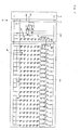
- FIG. 6 is an overall circuit diagram of a Embodiment of the invention, comprising a power supply unit 2 and an LED module 1 with an LED array 1a and that in FIG. 5 Circuit 1b shown for feedback of the brightness level shown on the power supply 2.
- FIG. 7 is an overall circuit diagram of a Embodiment of the invention, comprising a power supply unit 2 and an LED module 1 with an LED array 1a and that in FIG. 5 Circuit 1b shown for feedback of the brightness level shown on the power supply 2.
- FIG. 5 Circuit 1b shown for feedback of the brightness level shown on the power supply 2.
- other modules between the power supply and the LED array arrow X
- the LED array 1a has a plurality of parallel ones LED chains 14 on.
- the LED chains 14 and the reference LED chain 11 are each operated with the same current.
- the series connection on the anode side serves this purpose the LED chain with the base-emitter path of a transistor TK and an emitter resistor RE and the connection of the Base connections of these transistors.
- the emitter resistors have the same value. Alternatively, you can different emitter resistances can be provided, wherein then a division of the currents in the LED chains according to the reciprocal emitter resistance values.
- the reference LED chain 11 of the LED module generates a measurement signal that from an optical Output variable of the LED module, for example the brightness depends and in the form of a resistance between the Connections 13a and 13b is fed into the power supply 2.
- the power supply unit 2 regulates the operating current and / or the operating voltage of the LED module so that a predetermined optical target output variable, such as a minimum brightness, is observed, or it switches off the LED array.
- FIG. 7 shows further circuit modules 16, 17, 18 and 19 shown, each cumulatively or alternatively at the Invention, in particular in the case of a circuit according to FIG. 6 (Arrow X) can be used.
- Module 16 includes a transistor that is an "artificial Short circuit "can cause. On the part of the power supply 2 with such an artificial short circuit the electrical Supply of the LED module interrupted or even the whole Power supply switched off. This is preferably one A fuse is provided on the supply line irreversibly interrupts.
- This module 16 is preferably with a circuit according to Module 18 driven, in turn by means of a Signal line 20 (see FIG. 6) a signal is fed in, the failure of one or more LED chains of the LED array displays.
- module 18 there is an adjusting resistor and / or a thermal resistance is provided, which is also in the Measurement signal flows between the control lines 13a and 13b. For example, changes to the Operating temperature and a related change in Brightness of the LED array must be taken into account.
Landscapes
- Circuit Arrangement For Electric Light Sources In General (AREA)
Applications Claiming Priority (2)
| Application Number | Priority Date | Filing Date | Title |
|---|---|---|---|
| DE10208462 | 2002-02-27 | ||
| DE10208462A DE10208462A1 (de) | 2002-02-27 | 2002-02-27 | Beleuchtungsanordnung |
Publications (2)
| Publication Number | Publication Date |
|---|---|
| EP1341402A2 true EP1341402A2 (fr) | 2003-09-03 |
| EP1341402A3 EP1341402A3 (fr) | 2008-07-16 |
Family
ID=27675050
Family Applications (1)
| Application Number | Title | Priority Date | Filing Date |
|---|---|---|---|
| EP03004441A Withdrawn EP1341402A3 (fr) | 2002-02-27 | 2003-02-27 | Dispositif d' éclairage à module-LED |
Country Status (2)
| Country | Link |
|---|---|
| EP (1) | EP1341402A3 (fr) |
| DE (1) | DE10208462A1 (fr) |
Cited By (4)
| Publication number | Priority date | Publication date | Assignee | Title |
|---|---|---|---|---|
| EP1753267A1 (fr) * | 2005-08-04 | 2007-02-14 | Hella KG Hueck & Co. | Dispositif d'éclairage pour lampes de véhicule |
| DE102009056809A1 (de) * | 2009-12-04 | 2011-06-09 | Westiform Holding Ag | Leuchtreklame, insbesondere Leuchtbuchstabe |
| WO2013160446A1 (fr) * | 2012-04-26 | 2013-10-31 | Zumtobel Lighting Gmbh | Système et procédé d'évaluation de l'état d'un ensemble électronique utilisé à des fins d'éclairage |
| WO2016050521A1 (fr) * | 2014-09-29 | 2016-04-07 | Siemens Aktiengesellschaft | Dispositif et procédé pour contrôler un transmetteur de signal d'un feu de circulation comportant une diode électroluminescente |
Families Citing this family (3)
| Publication number | Priority date | Publication date | Assignee | Title |
|---|---|---|---|---|
| DE10245626A1 (de) * | 2002-09-30 | 2004-04-08 | Osram Opto Semiconductors Gmbh | Restwelligkeitsreduzierung bei LED-Ampelanwendungen bzw.Lichtsignaleinrichtungen |
| JP4439457B2 (ja) | 2005-02-14 | 2010-03-24 | 株式会社小糸製作所 | 車両用灯具システム |
| DE102005023295A1 (de) * | 2005-05-12 | 2006-11-16 | Siemens Ag | Schaltung zur Ansteuerung und Überwachung eines Lichtsignals |
Citations (2)
| Publication number | Priority date | Publication date | Assignee | Title |
|---|---|---|---|---|
| US6095661A (en) | 1998-03-19 | 2000-08-01 | Ppt Vision, Inc. | Method and apparatus for an L.E.D. flashlight |
| US6236331B1 (en) | 1998-02-20 | 2001-05-22 | Newled Technologies Inc. | LED traffic light intensity controller |
Family Cites Families (3)
| Publication number | Priority date | Publication date | Assignee | Title |
|---|---|---|---|---|
| US4983884A (en) * | 1989-08-29 | 1991-01-08 | Amp Incorporated | Constant intensity light source for fiber optic testing |
| US6153985A (en) * | 1999-07-09 | 2000-11-28 | Dialight Corporation | LED driving circuitry with light intensity feedback to control output light intensity of an LED |
| US6344641B1 (en) * | 1999-08-11 | 2002-02-05 | Agilent Technologies, Inc. | System and method for on-chip calibration of illumination sources for an integrated circuit display |
-
2002
- 2002-02-27 DE DE10208462A patent/DE10208462A1/de not_active Withdrawn
-
2003
- 2003-02-27 EP EP03004441A patent/EP1341402A3/fr not_active Withdrawn
Patent Citations (2)
| Publication number | Priority date | Publication date | Assignee | Title |
|---|---|---|---|---|
| US6236331B1 (en) | 1998-02-20 | 2001-05-22 | Newled Technologies Inc. | LED traffic light intensity controller |
| US6095661A (en) | 1998-03-19 | 2000-08-01 | Ppt Vision, Inc. | Method and apparatus for an L.E.D. flashlight |
Cited By (5)
| Publication number | Priority date | Publication date | Assignee | Title |
|---|---|---|---|---|
| EP1753267A1 (fr) * | 2005-08-04 | 2007-02-14 | Hella KG Hueck & Co. | Dispositif d'éclairage pour lampes de véhicule |
| DE102009056809A1 (de) * | 2009-12-04 | 2011-06-09 | Westiform Holding Ag | Leuchtreklame, insbesondere Leuchtbuchstabe |
| WO2013160446A1 (fr) * | 2012-04-26 | 2013-10-31 | Zumtobel Lighting Gmbh | Système et procédé d'évaluation de l'état d'un ensemble électronique utilisé à des fins d'éclairage |
| WO2016050521A1 (fr) * | 2014-09-29 | 2016-04-07 | Siemens Aktiengesellschaft | Dispositif et procédé pour contrôler un transmetteur de signal d'un feu de circulation comportant une diode électroluminescente |
| US10006616B2 (en) | 2014-09-29 | 2018-06-26 | Siemens Aktiengesellschaft | Device and method for monitoring a signal emitter comprising a light-emitting diode in a light-signal system |
Also Published As
| Publication number | Publication date |
|---|---|
| EP1341402A3 (fr) | 2008-07-16 |
| DE10208462A1 (de) | 2003-09-04 |
Similar Documents
| Publication | Publication Date | Title |
|---|---|---|
| DE10323437B4 (de) | Fahrzeugbeleuchtungseinrichtung | |
| DE102005047610B4 (de) | Beleuchtungssteuerschaltung für Fahrzeuglampen | |
| EP1161121A2 (fr) | Dispositif d'éclairage pour un véhicule | |
| DE102009060791A1 (de) | Lichtmodul für eine Beleuchtungseinrichtung eines Kraftfahrzeugs sowie Beleuchtungseinrichtung eines Kraftfahrzeugs mit einem solchen Lichtmodul | |
| DE19707986B4 (de) | Schaltungsanordnung zum Betreiben einer Entladungslampe | |
| EP2463174A1 (fr) | Dispositif et procédé pour remplacer une lampe à incandescence d'un signal lumineux | |
| DE10103611B4 (de) | Schaltungsanordnung zum Betreiben von mehreren Leuchtmitteln | |
| EP3124988B1 (fr) | Circuit de commande de diodes electroluminescentes pour un emetteur de signal d'une installation de signal lumineux | |
| EP0992961B1 (fr) | Circuit d'opération d'un panneau lumineux | |
| DE102006006778B4 (de) | Fahrzeugbeleuchtungssystem | |
| EP1233654A1 (fr) | Circuit et procédé d'adaptation de la courbe caractéristique d'une diode LED | |
| DE102008034524B4 (de) | Notlichteinheit | |
| EP1341402A2 (fr) | Dispositif d' éclairage à module-LED | |
| DE10329367B4 (de) | LED-Array, LED-Modul sowie Verwendung des LED-Moduls in einer Signalanlage | |
| WO2026052619A1 (fr) | Circuit d'alimentation ayant une fonction de surveillance | |
| DE102010055296A1 (de) | Leuchtmittel mit Farbortdimmung | |
| DE10114908A1 (de) | Dimmer | |
| DE602005004167T2 (de) | Elektrische Schaltung für LED Signallampen mit einer Schaltschwelle zum Umschalten zwischen Tages- und Nachtbetrieb | |
| DE112017007542B4 (de) | Fahrzeugbeleuchtungsvorrichtung | |
| DE102007047847B4 (de) | Verkehrssignalanlage mit Signalgebern und einer Steuereinrichtung zum Steuern von Leuchten in den Signalgebern | |
| DE10121380A1 (de) | Elektronisch abgesicherte Stromversorgung für Schaltungsgruppen, Anzeigevorrichtung für eine sich ändernde Information | |
| DE10257184B4 (de) | LED-Array und LED-Modul | |
| DE10206649A1 (de) | Anzeigevorrichtung | |
| DE102017223741B4 (de) | Verfahren zur Verringerung sichtbarer Flackereffekte in einer lichtemittierenden Diodenanordnung betrieben durch impulsbreitemodulierte Signale | |
| EP1286571A2 (fr) | Alimentation avec protection électronique pour un circuit et dispositif d'affichage des informations variables |
Legal Events
| Date | Code | Title | Description |
|---|---|---|---|
| PUAI | Public reference made under article 153(3) epc to a published international application that has entered the european phase |
Free format text: ORIGINAL CODE: 0009012 |
|
| AK | Designated contracting states |
Kind code of ref document: A2 Designated state(s): AT BE BG CH CY CZ DE DK EE ES FI FR GB GR HU IE IT LI LU MC NL PT SE SI SK TR |
|
| AX | Request for extension of the european patent |
Extension state: AL LT LV MK RO |
|
| RAP1 | Party data changed (applicant data changed or rights of an application transferred) |
Owner name: OSRAM OPTO SEMICONDUCTORS GMBH |
|
| RAP1 | Party data changed (applicant data changed or rights of an application transferred) |
Owner name: OSRAM OPTO SEMICONDUCTORS GMBH |
|
| PUAL | Search report despatched |
Free format text: ORIGINAL CODE: 0009013 |
|
| AK | Designated contracting states |
Kind code of ref document: A3 Designated state(s): AT BE BG CH CY CZ DE DK EE ES FI FR GB GR HU IE IT LI LU MC NL PT SE SI SK TR |
|
| AX | Request for extension of the european patent |
Extension state: AL LT LV MK RO |
|
| 17P | Request for examination filed |
Effective date: 20081114 |
|
| 17Q | First examination report despatched |
Effective date: 20090112 |
|
| AKX | Designation fees paid |
Designated state(s): CH DE FR GB LI |
|
| APBK | Appeal reference recorded |
Free format text: ORIGINAL CODE: EPIDOSNREFNE |
|
| APBN | Date of receipt of notice of appeal recorded |
Free format text: ORIGINAL CODE: EPIDOSNNOA2E |
|
| APBR | Date of receipt of statement of grounds of appeal recorded |
Free format text: ORIGINAL CODE: EPIDOSNNOA3E |
|
| APAV | Appeal reference deleted |
Free format text: ORIGINAL CODE: EPIDOSDREFNE |
|
| APBT | Appeal procedure closed |
Free format text: ORIGINAL CODE: EPIDOSNNOA9E |
|
| STAA | Information on the status of an ep patent application or granted ep patent |
Free format text: STATUS: THE APPLICATION IS DEEMED TO BE WITHDRAWN |
|
| 18D | Application deemed to be withdrawn |
Effective date: 20150901 |