EP1342646A2 - Drehwinkelsensor mit Erfassung der absoluten Winkelstellung durch eine einfache Vorrichtung - Google Patents
Drehwinkelsensor mit Erfassung der absoluten Winkelstellung durch eine einfache Vorrichtung Download PDFInfo
- Publication number
- EP1342646A2 EP1342646A2 EP03004387A EP03004387A EP1342646A2 EP 1342646 A2 EP1342646 A2 EP 1342646A2 EP 03004387 A EP03004387 A EP 03004387A EP 03004387 A EP03004387 A EP 03004387A EP 1342646 A2 EP1342646 A2 EP 1342646A2
- Authority
- EP
- European Patent Office
- Prior art keywords
- rotation
- output
- rotor
- detection signal
- angle
- Prior art date
- Legal status (The legal status is an assumption and is not a legal conclusion. Google has not performed a legal analysis and makes no representation as to the accuracy of the status listed.)
- Withdrawn
Links
Images



Classifications
-
- G—PHYSICS
- G01—MEASURING; TESTING
- G01D—MEASURING NOT SPECIALLY ADAPTED FOR A SPECIFIC VARIABLE; ARRANGEMENTS FOR MEASURING TWO OR MORE VARIABLES NOT COVERED IN A SINGLE OTHER SUBCLASS; TARIFF METERING APPARATUS; MEASURING OR TESTING NOT OTHERWISE PROVIDED FOR
- G01D5/00—Mechanical means for transferring the output of a sensing member; Means for converting the output of a sensing member to another variable where the form or nature of the sensing member does not constrain the means for converting; Transducers not specially adapted for a specific variable
- G01D5/12—Mechanical means for transferring the output of a sensing member; Means for converting the output of a sensing member to another variable where the form or nature of the sensing member does not constrain the means for converting; Transducers not specially adapted for a specific variable using electric or magnetic means
- G01D5/14—Mechanical means for transferring the output of a sensing member; Means for converting the output of a sensing member to another variable where the form or nature of the sensing member does not constrain the means for converting; Transducers not specially adapted for a specific variable using electric or magnetic means influencing the magnitude of a current or voltage
- G01D5/142—Mechanical means for transferring the output of a sensing member; Means for converting the output of a sensing member to another variable where the form or nature of the sensing member does not constrain the means for converting; Transducers not specially adapted for a specific variable using electric or magnetic means influencing the magnitude of a current or voltage using Hall-effect devices
- G01D5/145—Mechanical means for transferring the output of a sensing member; Means for converting the output of a sensing member to another variable where the form or nature of the sensing member does not constrain the means for converting; Transducers not specially adapted for a specific variable using electric or magnetic means influencing the magnitude of a current or voltage using Hall-effect devices influenced by the relative movement between the Hall device and magnetic fields
-
- B—PERFORMING OPERATIONS; TRANSPORTING
- B62—LAND VEHICLES FOR TRAVELLING OTHERWISE THAN ON RAILS
- B62D—MOTOR VEHICLES; TRAILERS
- B62D15/00—Steering not otherwise provided for
- B62D15/02—Steering position indicators ; Steering position determination; Steering aids
- B62D15/021—Determination of steering angle
- B62D15/0245—Means or methods for determination of the central position of the steering system, e.g. straight ahead position
-
- G—PHYSICS
- G01—MEASURING; TESTING
- G01D—MEASURING NOT SPECIALLY ADAPTED FOR A SPECIFIC VARIABLE; ARRANGEMENTS FOR MEASURING TWO OR MORE VARIABLES NOT COVERED IN A SINGLE OTHER SUBCLASS; TARIFF METERING APPARATUS; MEASURING OR TESTING NOT OTHERWISE PROVIDED FOR
- G01D5/00—Mechanical means for transferring the output of a sensing member; Means for converting the output of a sensing member to another variable where the form or nature of the sensing member does not constrain the means for converting; Transducers not specially adapted for a specific variable
- G01D5/02—Mechanical means for transferring the output of a sensing member; Means for converting the output of a sensing member to another variable where the form or nature of the sensing member does not constrain the means for converting; Transducers not specially adapted for a specific variable using mechanical means
- G01D5/04—Mechanical means for transferring the output of a sensing member; Means for converting the output of a sensing member to another variable where the form or nature of the sensing member does not constrain the means for converting; Transducers not specially adapted for a specific variable using mechanical means using levers; using cams; using gearing
-
- G—PHYSICS
- G01—MEASURING; TESTING
- G01D—MEASURING NOT SPECIALLY ADAPTED FOR A SPECIFIC VARIABLE; ARRANGEMENTS FOR MEASURING TWO OR MORE VARIABLES NOT COVERED IN A SINGLE OTHER SUBCLASS; TARIFF METERING APPARATUS; MEASURING OR TESTING NOT OTHERWISE PROVIDED FOR
- G01D2205/00—Indexing scheme relating to details of means for transferring or converting the output of a sensing member
- G01D2205/20—Detecting rotary movement
- G01D2205/26—Details of encoders or position sensors specially adapted to detect rotation beyond a full turn of 360°, e.g. multi-rotation
Definitions
- the present invention relates to rotation-angle detecting devices, and more particularly, to a low-profile and compact rotation-angle detecting device having a simple configuration.
- FIG. 7 is a plan view showing the inner configuration of the rotation-angle detecting device
- FIG. 8 is an explanatory view showing the output characteristics of the rotation-angle detecting device with respect to the rotation angle.
- a rotating member 23 is mounted inside a case body 22 made of insulating resin.
- the rotating member 23 is made of insulating resin, is shaped like a cylinder, and is rotatably supported by the case 22.
- a shaft of a steering wheel of an automobile extends through the rotating member 23 so that the rotating member 23 is rotated clockwise and counterclockwise together with the steering wheel.
- a helical gear 23a having a plurality of teeth is formed on the entire outer peripheral surface of the rotating member 23.
- a rotation shaft 29 is rotatably provided inside the case body 22.
- a driving gear 28 is fixed to the rotation shaft 29.
- a helical gear 28a having a plurality of teeth is formed on the entire outer peripheral surface of the driving gear 28, and is meshed with the helical gear 23a of the rotating member 23.
- a first ring-shaped magnet 25A having a pair of magnetic poles on its outer peripheral surface is provided adjacent to the driving gear 28 so that it is coaxial with the rotation shaft 29.
- the rotation shaft 29 is made of metal such as brass or aluminum, and has a spiral screw groove 29a formed from the center to one end.
- a moving member 24 is engaged with the screw groove 29a.
- the moving member 24 has a through hole extending from one end face to the other end face in the moving direction.
- the through hole has, on its inner peripheral surface, an internal thread (not shown) to be meshed with the screw grove 29a formed on the rotation shaft 29.
- a second magnet 25B having a pair of magnetic poles is fixedly attached to the lower surface of the moving member 24.
- the moving member 24 is guided inside the case body 22 so as to linearly move in the axial direction of the rotation shaft 29.
- the rotating member 23 rotates and the driving gear 28 and the rotation shaft 29 also rotate, the moving member 24 and the second magnet 25B reciprocally move in the axial direction of the rotation shaft 29.
- a substrate 30 on which first and second Hall elements (detection means) 26A and 26B are mounted is fixed in the lower part of the case body 22.
- a pair of first Hall elements 26A face the first magnet 25A
- the second Hall element 26B faces the second magnet 25B.
- the first Hall elements 26A detect the magnetic displacement of the first magnet 25A, and output predetermined sinusoidal waves 101 and 102 shown in FIG. 8 as first detection signals in response to the rotation.
- the second Hall element 26B detects the magnetic displacement of the second magnet 25B, and outputs a signal 103, which linearly changes over the entire rotation angle range of the steering wheel, as a second detection signal.
- the absolute angle of the rotation angle (steering angle) of the steering wheel can be detected on the basis of the first and second detection signals output from the first and second Hall elements 26A and 26B.
- a driving gear with a helical gear to be meshed with the helical gear on the outer peripheral surface of the rotating member must be provided, and the driving gear and the rotating member are arranged so that their rotation axes are orthogonal to each other. Consequently, the thickness and size of the rotation-axis detecting device are increased by of the diameter of the driving gear.
- the present invention provides a rotation-angle detecting device including a rotor, a first output mechanism for outputting a first detection signal in response to the rotation of the rotor, and a second output mechanism for outputting a second detection signal in response to the rotation of the rotor, wherein a first transmission gear and a second transmission gear having intermittent teeth are arranged along the rotation axis on an outer peripheral surface of the rotor, the first output mechanism includes a first output gear that is meshed with the first transmission gear and that rotates on an axis in parallel with the axis of the rotor, and a first output section for outputting the first detection signal in response to the rotation of the first output gear, the second output mechanism includes a second output gear that is meshed with the second transmission gear and that rotates on an axis in parallel with the axis of the rotor, and a second output section for outputting the second detection signal in response to the rotation of the second output gear, and the rotation angle of the rotor
- the first detection signal has a predetermined period and continues within the rotation range of the rotor, and the second detection signal rises or falls stepwise within the rotation range of the rotor.
- the second output gear includes upper and lower tooth segments arranged vertically and alternately, the upper tooth segment is meshed with the second transmission gear, and the lower tooth segment engages with the outer peripheral surface of the rotor after the upper tooth segment is rotated by a predetermined angle in engagement with the second transmission gear, thereby preventing the second output gear from returning.
- the second output gear can be prevented from returning with a simple structure, and the accuracy in detecting the rotation angle can be increased.
- each of the first output section and the second output section includes a permanent magnet with different magnetic poles opposing each other with the rotation axis therebetween, and a magnetoresistive element whose resistance varies depending on the direction of a magnetic field of the permanent magnet.
- the rotation angle can be detected in a non-contact manner.
- the magnetoresistive element since the magnetoresistive element is used, the detection accuracy can be increased, regardless of assembly accuracy.
- the first output mechanism is a non-contact magnetic output means
- the second output mechanism is a contact output means
- the second output mechanism is less expensive than the first output mechanism, the cost can be reduced. Moreover, since the number of revolutions of the second output mechanism is smaller than that of the first output mechanism, the second output mechanism can stand long use.
- the second output mechanism is a rotary variable resistor.
- the rotation-angle detecting device can be provided at a lower price.
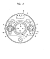
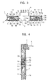
- a rotation-angle detecting device according to an embodiment of the present invention will be described below with reference to FIGS. 1 to 6.
- the rotation-angle detecting device of this embodiment has an upper case 1 made of insulating resin and shaped like a disk having a center hole 1a.
- the upper case 1 has a stepped portion 1b on its outer periphery.
- a lead-wire extending portion 4 is formed at an end of the upper side of the upper case 1, and lead wires 5 extend outside therefrom.
- a lower case 2 includes a bottom plate 2b shaped like a disk having a center hole 2a, and a side wall 2d.
- the bottom plate 2b has a ring-shaped projecting portion 2c.
- a stepped portion 2e is formed at the upper end of the side wall 2d, and is engaged with the stepped portion 1b of the upper case 1.
- the upper case 1 and the lower case 2 are fastened together by a screw 1c.
- a rotor 3 is made of insulating resin and shaped like a cylinder. Ribs 3a to be engaged with an external rotating shaft are formed on the inner periphery of the rotor 3.
- a second transmission gear 3b is formed on the upper outer periphery of the rotor 3, and two intermittent teeth 3c are formed on the opposing sides of the second transmission gear 3b so that they are spaced 180° apart from each other. Teeth are provided on the entirety of the lower outer periphery of the rotor 3, thereby forming a first transmission gear 3d.
- the rotor 3 is held between the upper case 1 and the lower case 2 so that it can rotate clockwise and counterclockwise relative to the upper case 1 and the lower case 2.
- a first output gear 6 is a general type of gear that is made of insulating resin, that has an axis in parallel with the axis of the rotor 3, and that is provided with teeth 6c on its entire periphery.
- a projection 6a is formed at the center of one side face of the first output gear 6, and a circular recess 6b is formed at the center of the other side face.
- the teeth 6c of the first output gear 6 are engaged with the teeth 3e of the first transmission gear 3d formed on the lower periphery of the rotor 3.
- the first output gear 6 rotates 360° while the rotor 3 rotates 180°.
- a second output gear 7 is a double gear that is made of insulating resin, that has an axis in parallel with the axis of the rotor 3, and that includes two upper and lower tooth segments placed in the axial direction so that upper teeth 7c and lower teeth 7d are alternately arranged.
- the teeth 7c and 7d are formed on the entire periphery.
- a projection 7a is formed at the center of one side face of the second output gear 7, and a circular recess 7b is formed at the center of the other side face.
- the upper teeth 7c and the lower teeth 7d of the second output gear 7 are to be engaged with the intermittent teeth 3c of the second transmission gear 3b formed on the upper side of the outer periphery of the rotor 3.
- Two ring-shaped permanent magnets 8 each have different magnetic-poles that oppose each other with the rotating shaft therebetween at the positions spaced 180° apart from each other.
- the permanent magnets 8 are fixedly mounted inside the teeth of the first output gear 6 and the second output gear 7, respectively.
- Two support members 9 are formed of a plate made of insulating resin. Both ends in the longitudinal direction thereof are inclined downward, and are fixed to the lower case 2. Ring-shaped projections 9a are respectively formed on the lower sides of the support members 9. The projection 6a formed on one side face of the first output gear 6 is fitted in the ring-shaped projection 9a of one of the support members 9, and the circular recess 6a on the other side face is fitted on the ring-shaped projection 2c of the bottom plate 2b of the lower case 2, so that the first output gear 6 is rotatably supported while being retained from both the sides.
- the projection 7a formed on one side face of the second output gear 7 is fitted in the ring-shaped projection 9a of the other support member 9, and the circular recess 7a on the other side face is fitted on the ring-shaped projection 2c of the bottom plate 2b of the lower case 2, so that the second transmission gear 7 is also rotatably supported while being retained from both the sides.
- a printed wiring board 10 is shaped like a disk having a circular hole 10a at its center, and is fixed to the lower side of the upper case 1. The output from the printed wiring board 10 is led outside by the lead wires 5 through the lead-wire extending portion 4.
- Magnetoelectric transducers 11 are each formed of an assembly of a plurality of giant magnetoresistive (GMR) elements, and the GMR elements form a bridge circuit (not shown).
- the magnetoelectric transducers 11 are mounted on the printed wiring board 10 so that they oppose the ring-shaped permanent magnets 8 that corotate with the first output gear 6 and the second output gear 7.
- the resistance of the magnetoelectric transducers 11 varies depending on the direction of the magnetic field of the permanent magnets 8.
- the permanent magnet 8 that corotates with the first output gear 6, and the magnetoelectric transducer 11 opposed thereto constitute a first detecting section
- the permanent magnet 8 that corotates with the second output gear 7, and the magnetoelectric transducer 11 opposed thereto constitute a second detecting section. As shown in FIG.
- a sawtooth periodic first detection signal Va is obtained from the first detecting section, and a second detection signal Vb that rises stepwise is obtained from the second detecting section.
- the first output gear 6 and the first detecting section constitute a first output mechanism
- the second output gear 7 and the second detecting section constitute a second output mechanism.
- the first and second detection signals Va and Vb are output from the first and second output mechanisms.
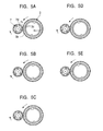
- FIG. 5A when the rotor 3 rotates counterclockwise (in the direction shown by the arrow in the figure), the outside of the preceding tooth of the intermittent teeth 3c hits an upper tooth 7c of the second output gear 7, and the second output gear 7 slightly rotates clockwise (in the direction shown by the arrow in the figure).
- FIG. 5B a lower teeth 7d of the second output gear 7 enters a space between the intermittent teeth 3b, and is pressed by the wall of the following tooth, so that the second output gear 7 starts to further rotate clockwise.
- FIGS. 5C and 5D since the lower tooth 7d of the second output gear 7 is continuously pressed, the second output gear 7 further rotates clockwise.
- the lower tooth 7d With this rotation, the lower tooth 7d is coming out of the space between the intermittent teeth 3c. In FIG. 5E, the lower tooth 7d is completely out of the space. In this case, the lower tooth 7d and the leading end of a lower tooth 7d on the upstream side in the rotating direction contact the peripheral surface of the rotor 3 connected to the space between the teeth 3c, thereby preventing the second output gear 7 from further rotating. In this way, the second output gear 7 rotates by a predetermined angle (an angle corresponding to one pitch of the upper teeth 7c or the lower teeth 7d).
- the second output gear 7 does not rotate until the rotor 3 has rotated approximately 180°.
- the other intermittent teeth 3c spaced 180° apart in the rotor 3 are brought into contact with an upper tooth 7c of the second output gear 7, and the same rotation as above is performed. Therefore, the second output gear 7 rotates by a predetermined angle (an angle corresponding to one pitch of the upper teeth 7c or the lower teeth 7d) every time the rotor 3 rotates 180°.
- a first detection signal Va includes sawtooth pulses having a period of 180°, and each of the pulses includes a portion that gradually and linearly rises, and a portion that falls sharply.
- the portion that gradually and linearly rises is obtained by calculating, with an arithmetic element (not shown) mounted on the printed wiring board 10, a sine-wave output and a cosine-wave output from the bridge circuit in the magnetoelectric transducer 11 in conjunction with the ring-shaped permanent magnet 8 that corotates with the first output gear 6, and converting the calculated value into an output value that is linear with respect to the rotation angle of the rotor 3.
- the portion that sharply falls is a portion in which one period of the first detection signal Va ends and the first detection signal Va returns to its initial value.
- a second detection signal Vb has a waveform that rises stepwise at every 180°.
- the intermittent teeth 3c are spaced 180° apart from each other in the rotating direction on the periphery of the rotor 3, and the second output gear 7 formed of a double gear to be meshed with the intermittent teeth 3c of the rotor 3 is rotated by a predetermined angle by the intermittent teeth 3c every time the rotor 3 rotates 180°.
- the second output gear 7 is rotated by the predetermined angle, the output from the bridge circuit in the magnetoelectric transducer 11 is changed by the permanent magnet 8 that corotates with the second output gear 7, and an increase corresponding to a stepwise rise of the second detection signal Vb is found by calculation.
- the signal rises stepwise at every 180°, that is, every time the intermittent teeth 3c of the rotor 3 and the second output gear 7 are engaged with each other.
- the center of the gradually rising portion of the second detection signal Vb corresponds to the sharply rising portion of the first detection signal Va.
- the flat portion of the second detection signal Vb links gradually rising portions.
- the position number of the flat portion is shown by the numeral in FIG. 6.
- the center of the 0-th flat portion corresponds to a rotation angle of 0°.
- N is an integer
- B is an angle calculated from a portion of the first detection signal Va that gradually and linearly rises
- VH is an upper threshold of the first detection signal Va corresponding to the lower end of a gradually rising portion of the second detection signal Vb
- VL is a lower threshold of the first detection signal Va corresponding to the upper end of a gradually rising portion of the second detection signal Vb
- ⁇ a is a rotation angle range set corresponding to each flat portion (a rotation angle range corresponding to one period of the first detection signal: 180° in this embodiment)
- ⁇ 0 is an arbitrary rotation angle (90° in this embodiment).
- a value of the first detection signal Va set corresponding to the lower end of the gradually rising potion is designated VH
- a value of the first detection signal Va set corresponding to the upper end of the gradually rising portion is designated VL.
- a rotation angle range B is first found on the basis of the first detection signal Va.
- a rotation angle range B is similarly found on the basis of the value of the first detection signal Va.
- the first detection signal Va is detected corresponding thereto.
- the absolute angle A (°) is given by an expression N ⁇ a- ⁇ 0+B.
- the absolute angle A (°) is given by an expression (N+1) ⁇ a- ⁇ 0+B.
- the absolute angle A (° ) is given by an expression (N+1) ⁇ a- ⁇ 0.
- the absolute angle of the rotation angle is found on the basis of the first detection signal Va and the second detection signal Vb, in a manner similar to the above.
- the value of the second detection signal Vb is included in a gradually rising portion, the position in the gradually rising portion at which the second detection signal Vb exists is calculated, and the absolute angle A is found using the calculated value.
- the first detection signal Va includes sawtooth continuous pulses each having a portion that gradually and linearly rises and a potion that sharply falls within the detection range, and the second detection signal Vb rises stepwise.
- the first detection signal Va may include sawtooth continuous pulses each having a portion that gradually and linearly falls and a portion that rises sharply, and the second detection signal Vb may fall stepwise.
- GMR element is used as the magnetoresistive element in the above embodiment, it may be replaced with a MR element, a TMR element, or a magnetoelectric transducer element such as a Hall element.
- the second output mechanism may be a contact output means such as a rotary variable resistor or a rotary encoder.
Landscapes
- Physics & Mathematics (AREA)
- General Physics & Mathematics (AREA)
- Engineering & Computer Science (AREA)
- Chemical & Material Sciences (AREA)
- Combustion & Propulsion (AREA)
- Transportation (AREA)
- Mechanical Engineering (AREA)
- Transmission And Conversion Of Sensor Element Output (AREA)
- Measurement Of Length, Angles, Or The Like Using Electric Or Magnetic Means (AREA)
Applications Claiming Priority (4)
| Application Number | Priority Date | Filing Date | Title |
|---|---|---|---|
| JP2002058810 | 2002-03-05 | ||
| JP2002058810 | 2002-03-05 | ||
| JP2002238497A JP4209155B2 (ja) | 2002-03-05 | 2002-08-19 | 回転角検出装置 |
| JP2002238497 | 2002-08-19 |
Publications (2)
| Publication Number | Publication Date |
|---|---|
| EP1342646A2 true EP1342646A2 (de) | 2003-09-10 |
| EP1342646A3 EP1342646A3 (de) | 2007-01-24 |
Family
ID=27759728
Family Applications (1)
| Application Number | Title | Priority Date | Filing Date |
|---|---|---|---|
| EP03004387A Withdrawn EP1342646A3 (de) | 2002-03-05 | 2003-03-03 | Drehwinkelsensor mit Erfassung der absoluten Winkelstellung durch eine einfache Vorrichtung |
Country Status (3)
| Country | Link |
|---|---|
| US (1) | US6720762B2 (de) |
| EP (1) | EP1342646A3 (de) |
| JP (1) | JP4209155B2 (de) |
Cited By (10)
| Publication number | Priority date | Publication date | Assignee | Title |
|---|---|---|---|---|
| EP1688729A1 (de) * | 2005-02-08 | 2006-08-09 | Delphi Technologies, Inc. | Gehäuse für einen kontaktlosen Positionssensor mit Verwendung von einem bekannten Drehmomentsensor |
| WO2007048562A1 (de) * | 2005-10-24 | 2007-05-03 | Valeo Schalter Und Sensoren Gmbh | Lenkwinkelsensor, lenkwinkelsensorsystem und verfahren hierfür |
| EP1792806A1 (de) | 2005-11-30 | 2007-06-06 | Valeo Schalter und Sensoren GmbH | Lenkwinkelsensor |
| FR2898973A1 (fr) * | 2006-03-22 | 2007-09-28 | Sc2N Sa | Capteur d'angle |
| WO2012019946A1 (de) * | 2010-08-13 | 2012-02-16 | Valeo Schalter Und Sensoren Gmbh | Vorrichtung zum erfassen eines positionswinkels eines drehbaren bauteils eines fahrzeugs sowie fahrzeug mit einer derartigen vorrichtung |
| EP2093538A4 (de) * | 2006-10-27 | 2012-04-25 | Furukawa Electric Co Ltd | Drehwinkeldetektionseinrichtung und drehwinkeldetektionsverfahren |
| EP1876423A3 (de) * | 2006-07-04 | 2013-09-04 | Toyo Denso Kabushiki Kaisha | Sensor für Steuerruderwinkel |
| CN104677388A (zh) * | 2014-08-29 | 2015-06-03 | 北京精密机电控制设备研究所 | 一种用于中空结构的空间机械臂旋转关节的多圈式绝对位置检测装置 |
| EP2715275A4 (de) * | 2011-05-25 | 2015-12-30 | Sensata Technologies Inc | Anordnung aus magnetischen positionssensoren zur messung der drehwinkellage einer rotierenden struktur |
| CN107994430A (zh) * | 2017-11-16 | 2018-05-04 | 中国第汽车股份有限公司 | 一种汽车用时钟弹簧 |
Families Citing this family (22)
| Publication number | Priority date | Publication date | Assignee | Title |
|---|---|---|---|---|
| US7023200B2 (en) * | 2002-06-18 | 2006-04-04 | Siemens Vdo Automotive Corporation | Non-contacting large angle rotary position sensor for rotating shaft |
| JP2005055256A (ja) * | 2003-08-01 | 2005-03-03 | Yazaki Corp | 舵角センサ |
| JP2005077305A (ja) * | 2003-09-02 | 2005-03-24 | Matsushita Electric Ind Co Ltd | 回転角度およびトルク検出装置 |
| US7583080B2 (en) * | 2005-02-10 | 2009-09-01 | Panasonic Corporation | Rotation angle detection device and rotation angle correction method |
| US7116100B1 (en) * | 2005-03-21 | 2006-10-03 | Hr Textron, Inc. | Position sensing for moveable mechanical systems and associated methods and apparatus |
| EP1948899B1 (de) * | 2005-11-18 | 2013-02-13 | Automatic Technology (Australia) Pty Ltd. | Vorrichtung zur überwachung der bewegung eines beweglichen verschlusses |
| US7339370B2 (en) * | 2005-12-09 | 2008-03-04 | Bourns, Inc. | Position and torque sensor |
| KR100757373B1 (ko) | 2006-10-19 | 2007-09-11 | 엘지이노텍 주식회사 | 조향각 센싱장치 |
| JP2008128962A (ja) * | 2006-11-24 | 2008-06-05 | Alps Electric Co Ltd | 絶対角検出装置 |
| DE102007009389A1 (de) * | 2007-02-20 | 2008-08-21 | Bizerba Gmbh & Co. Kg | Kraftmessvorrichtung und Verfahren zur Signalauswertung |
| JP4992516B2 (ja) * | 2007-04-02 | 2012-08-08 | パナソニック株式会社 | 回転角度検出装置 |
| JP2009145076A (ja) * | 2007-12-11 | 2009-07-02 | Hitachi Cable Ltd | 回転角度検出装置 |
| DE102008008835B4 (de) * | 2008-02-13 | 2010-04-22 | Zf Friedrichshafen Ag | Vorrichtung zum Ermitteln eines Drehmoments |
| JP4607211B2 (ja) * | 2008-06-27 | 2011-01-05 | 株式会社日本自動車部品総合研究所 | 回転角検出装置 |
| DE102009011352B3 (de) * | 2009-03-05 | 2010-07-15 | Bourns, Inc., Riverside | Torsionswinkelsensor |
| JP2010269667A (ja) * | 2009-05-20 | 2010-12-02 | Alps Electric Co Ltd | 多回転角度検出装置 |
| JP5315212B2 (ja) * | 2009-10-29 | 2013-10-16 | 日立オートモティブシステムズ株式会社 | 回転角度センサ異常検出装置、モータ制御システム、電動パワーステアリング |
| DE102010024782A1 (de) * | 2010-06-23 | 2011-12-29 | Leopold Kostal Gmbh & Co. Kg | Winkelsensor |
| US8448528B2 (en) | 2010-09-27 | 2013-05-28 | Bourns Incorporated | Three-piece torque sensor assembly |
| US8390276B2 (en) | 2010-09-27 | 2013-03-05 | Bourns Incorporated | Target magnet assembly for a sensor used with a steering gear |
| CN108062112B (zh) * | 2017-11-03 | 2020-03-24 | 兰州飞行控制有限责任公司 | 一种双余度角位置检测装置 |
| CN210971266U (zh) * | 2019-11-29 | 2020-07-10 | 罗伯特·博世有限公司 | 扭矩角度传感器 |
Family Cites Families (11)
| Publication number | Priority date | Publication date | Assignee | Title |
|---|---|---|---|---|
| FR2668258B1 (fr) * | 1990-10-19 | 1994-05-13 | Cartier Systemes G | Capteur d'angle de rotation pour detecter le sens de rotation et/ou le nombre de tours effectues, et dispositif de direction assitee de vehicule comportant un tel capteur. |
| JP2738199B2 (ja) * | 1992-03-02 | 1998-04-08 | 三菱電機株式会社 | 回転又は移動検出方法及びその装置 |
| DE19506938A1 (de) * | 1995-02-28 | 1996-08-29 | Bosch Gmbh Robert | Verfahren und Vorrichtung zur Winkelmessung bei einem drehbaren Körper |
| DE19601965A1 (de) * | 1996-01-20 | 1997-07-24 | Teves Gmbh Alfred | Lenkwinkelsensor mit Umdrehungszählwerk |
| DE69819574T2 (de) * | 1997-02-14 | 2004-09-16 | Alps Electric Co., Ltd. | Rotationsdetektionsvorrichtung für Multirotationskörper |
| DE19739823A1 (de) | 1997-09-11 | 1999-03-18 | Bosch Gmbh Robert | Verfahren und Vorrichtung zur Messung des Winkels eines ersten drehbaren Körpers |
| DE19838731C2 (de) * | 1998-08-26 | 2000-07-13 | Kostal Leopold Gmbh & Co Kg | Lenkwinkelsensor |
| DE19855960A1 (de) * | 1998-12-04 | 2000-06-08 | Bosch Gmbh Robert | Vorrichtung und Verfahren zur Messung der Winkellage eines drehbaren Körpers |
| JP2000205811A (ja) * | 1999-01-08 | 2000-07-28 | Alps Electric Co Ltd | 回転型センサ |
| DE19933047A1 (de) * | 1999-07-15 | 2001-01-18 | Valeo Schalter & Sensoren Gmbh | Lenkstockmodul mit Lenkwinkelsensor und Blinkerrückstellung |
| DE19962241A1 (de) * | 1999-12-22 | 2001-07-12 | Ruf Electronics Gmbh | Positionssensor |
-
2002
- 2002-08-19 JP JP2002238497A patent/JP4209155B2/ja not_active Expired - Fee Related
-
2003
- 2003-02-27 US US10/377,919 patent/US6720762B2/en not_active Expired - Fee Related
- 2003-03-03 EP EP03004387A patent/EP1342646A3/de not_active Withdrawn
Cited By (13)
| Publication number | Priority date | Publication date | Assignee | Title |
|---|---|---|---|---|
| EP1688729A1 (de) * | 2005-02-08 | 2006-08-09 | Delphi Technologies, Inc. | Gehäuse für einen kontaktlosen Positionssensor mit Verwendung von einem bekannten Drehmomentsensor |
| US7363825B2 (en) | 2005-02-08 | 2008-04-29 | Delphi Technologies, Inc. | Non-contact position sensor housing using existing torque sensor probe |
| WO2007048562A1 (de) * | 2005-10-24 | 2007-05-03 | Valeo Schalter Und Sensoren Gmbh | Lenkwinkelsensor, lenkwinkelsensorsystem und verfahren hierfür |
| EP1792806A1 (de) | 2005-11-30 | 2007-06-06 | Valeo Schalter und Sensoren GmbH | Lenkwinkelsensor |
| FR2898973A1 (fr) * | 2006-03-22 | 2007-09-28 | Sc2N Sa | Capteur d'angle |
| EP1876423A3 (de) * | 2006-07-04 | 2013-09-04 | Toyo Denso Kabushiki Kaisha | Sensor für Steuerruderwinkel |
| EP2093538A4 (de) * | 2006-10-27 | 2012-04-25 | Furukawa Electric Co Ltd | Drehwinkeldetektionseinrichtung und drehwinkeldetektionsverfahren |
| US8265897B2 (en) | 2006-10-27 | 2012-09-11 | Furukawa Electric Co., Ltd | Rotation angle detector and process for detecting rotation angle |
| WO2012019946A1 (de) * | 2010-08-13 | 2012-02-16 | Valeo Schalter Und Sensoren Gmbh | Vorrichtung zum erfassen eines positionswinkels eines drehbaren bauteils eines fahrzeugs sowie fahrzeug mit einer derartigen vorrichtung |
| EP2715275A4 (de) * | 2011-05-25 | 2015-12-30 | Sensata Technologies Inc | Anordnung aus magnetischen positionssensoren zur messung der drehwinkellage einer rotierenden struktur |
| CN104677388A (zh) * | 2014-08-29 | 2015-06-03 | 北京精密机电控制设备研究所 | 一种用于中空结构的空间机械臂旋转关节的多圈式绝对位置检测装置 |
| CN107994430A (zh) * | 2017-11-16 | 2018-05-04 | 中国第汽车股份有限公司 | 一种汽车用时钟弹簧 |
| CN107994430B (zh) * | 2017-11-16 | 2024-05-07 | 中国第一汽车股份有限公司 | 一种汽车用时钟弹簧 |
Also Published As
| Publication number | Publication date |
|---|---|
| US20030169034A1 (en) | 2003-09-11 |
| US6720762B2 (en) | 2004-04-13 |
| JP4209155B2 (ja) | 2009-01-14 |
| EP1342646A3 (de) | 2007-01-24 |
| JP2003329483A (ja) | 2003-11-19 |
Similar Documents
| Publication | Publication Date | Title |
|---|---|---|
| US6720762B2 (en) | Rotation-angle detecting device capable of detecting absolute angle with simple configuration | |
| US6630823B2 (en) | Rotation angle detector | |
| US7276899B2 (en) | Positional transducer and motor driven gear changer for a bicycle | |
| JP5480967B2 (ja) | 多周期的絶対位置検出器 | |
| US6687647B2 (en) | Rotation-angle detecting device capable of precisely detecting absolute angle | |
| CN205484398U (zh) | 传感装置、传感系统及转向系统 | |
| JP2018132360A (ja) | ロータリエンコーダ及びその絶対角度位置検出方法 | |
| JP7596620B2 (ja) | マルチターン測定システム | |
| JP2010534330A (ja) | 軸貫通非接触の多回転絶対位置磁気センサ | |
| US8573086B2 (en) | Lever operation device | |
| EP2715275A1 (de) | Anordnung aus magnetischen positionssensoren zur messung der drehwinkellage einer rotierenden struktur | |
| CN102654385A (zh) | 传感器装置 | |
| JP2025500385A (ja) | 磁気センサシステム | |
| JP2006220529A (ja) | 絶対回転角度およびトルク検出装置 | |
| US20240308572A1 (en) | Steering system | |
| KR100866904B1 (ko) | 자기장의 각도변화를 이용한 위치센서 | |
| KR100460423B1 (ko) | 차량의 조향각 검출 장치 | |
| JP2006090982A (ja) | 回転角度検出装置 | |
| WO2008050843A1 (en) | Rotation angle detecting device | |
| JP4003598B2 (ja) | 操舵角検出装置 | |
| KR100458191B1 (ko) | 차량의 조향각 검출 장치 | |
| CN211317206U (zh) | 一种绝对式角度测量装置 | |
| KR102225725B1 (ko) | 각도 및 토크 센서 | |
| KR100460421B1 (ko) | 차량의 조향각 검출 장치 | |
| JP2004150950A (ja) | 回転角検出装置 |
Legal Events
| Date | Code | Title | Description |
|---|---|---|---|
| PUAI | Public reference made under article 153(3) epc to a published international application that has entered the european phase |
Free format text: ORIGINAL CODE: 0009012 |
|
| AK | Designated contracting states |
Kind code of ref document: A2 Designated state(s): AT BE BG CH CY CZ DE DK EE ES FI FR GB GR HU IE IT LI LU MC NL PT SE SI SK TR |
|
| AX | Request for extension of the european patent |
Extension state: AL LT LV MK RO |
|
| PUAL | Search report despatched |
Free format text: ORIGINAL CODE: 0009013 |
|
| AK | Designated contracting states |
Kind code of ref document: A3 Designated state(s): AT BE BG CH CY CZ DE DK EE ES FI FR GB GR HU IE IT LI LU MC NL PT SE SI SK TR |
|
| AX | Request for extension of the european patent |
Extension state: AL LT LV MK RO |
|
| RIC1 | Information provided on ipc code assigned before grant |
Ipc: B62D 15/02 20060101ALI20061219BHEP Ipc: G01B 21/22 20060101AFI20061219BHEP |
|
| 17P | Request for examination filed |
Effective date: 20070302 |
|
| 17Q | First examination report despatched |
Effective date: 20070712 |
|
| AKX | Designation fees paid |
Designated state(s): DE FR GB SE |
|
| STAA | Information on the status of an ep patent application or granted ep patent |
Free format text: STATUS: THE APPLICATION IS DEEMED TO BE WITHDRAWN |
|
| 18D | Application deemed to be withdrawn |
Effective date: 20111215 |