EP1342648A2 - Système pour mesurer l'ampleur des rotations d'une colonne de direction - Google Patents
Système pour mesurer l'ampleur des rotations d'une colonne de direction Download PDFInfo
- Publication number
- EP1342648A2 EP1342648A2 EP03004576A EP03004576A EP1342648A2 EP 1342648 A2 EP1342648 A2 EP 1342648A2 EP 03004576 A EP03004576 A EP 03004576A EP 03004576 A EP03004576 A EP 03004576A EP 1342648 A2 EP1342648 A2 EP 1342648A2
- Authority
- EP
- European Patent Office
- Prior art keywords
- steering
- angle
- steering control
- rotation
- change
- Prior art date
- Legal status (The legal status is an assumption and is not a legal conclusion. Google has not performed a legal analysis and makes no representation as to the accuracy of the status listed.)
- Granted
Links
Images
Classifications
-
- B—PERFORMING OPERATIONS; TRANSPORTING
- B62—LAND VEHICLES FOR TRAVELLING OTHERWISE THAN ON RAILS
- B62D—MOTOR VEHICLES; TRAILERS
- B62D15/00—Steering not otherwise provided for
- B62D15/02—Steering position indicators ; Steering position determination; Steering aids
- B62D15/021—Determination of steering angle
-
- B—PERFORMING OPERATIONS; TRANSPORTING
- B62—LAND VEHICLES FOR TRAVELLING OTHERWISE THAN ON RAILS
- B62D—MOTOR VEHICLES; TRAILERS
- B62D5/00—Power-assisted or power-driven steering
- B62D5/04—Power-assisted or power-driven steering electrical, e.g. using an electric servo-motor connected to, or forming part of, the steering gear
- B62D5/0457—Power-assisted or power-driven steering electrical, e.g. using an electric servo-motor connected to, or forming part of, the steering gear characterised by control features of the drive means as such
Definitions
- the invention relates to a device for detecting a change in the angle of rotation of a steering column of a motor vehicle with a steering angle sensor interacting with the steering column and an electric motor of a power steering device, which are coupled to an electronic steering control device.
- DE 39 08 217 C2 discloses a control device for controlling an electric power steering device of a motor vehicle, in which the desired current supplied to an electric motor is controlled as a function of the torque transmitted via a steering spindle and the power steering device is supported by the electric motor.
- the control device has a steering angle sensor for detecting changes in the angle of rotation of the steering column when the steering wheel is turned.
- the control device includes a device that determines a state in which the steering angle assumes a value that corresponds to or exceeds a predetermined angle.
- a current current of the electric motor is stored as a limiting current and compared with the target current. The lower of the two streams is selected and used to control the electric power steering device. This control device works only when the ignition is switched on in the operating state of the motor vehicle.
- an electronic stabilization program for a motor vehicle is known from practice.
- a steering angle sensor and a speed sensor on the wheels permanently monitor the direction of travel desired by the driver.
- a yaw angle sensor and lateral acceleration sensors permanently monitor the actual direction of travel of the motor vehicle.
- the electronic stabilization program automatically intervenes in driving operation in the event of serious deviations between the compared determined data by braking individual wheels to stabilize the motor vehicle.
- Both the electric power steering and the electronic stabilization program use signals from steering angle sensors with regard to the change in the angle of rotation of the steering column, the requirements for the type and quality of the signals being different.
- Relatively inexpensive steering angle sensors are used in connection with the electric power steering, in which an output signal is repeated cyclically. The actual steering angle is calculated using a calibration algorithm. If the steering wheel and thus the steering column are changed when the ignition is switched off, it is necessary to first run through the calibration algorithm to provide the correct steering angle information.
- steering angle sensors are used in particular in electronic stabilization programs, which always provide the correct steering angle even when the steering wheel is turned several times. Such steering angle sensors are called multiturn steering angle sensors and have one complex structure, which is why they are relatively expensive.
- the different steering angle sensors and a steering control device coupled to them When the ignition is switched off, the different steering angle sensors and a steering control device coupled to them are put into an idle state in which they absorb a relatively low quiescent current.
- a permanent power supply which would cause a permanently activated state and thus a detection of a change in the angle of rotation of the steering column when the ignition is switched off, is not possible due to the amount of current required for this.
- the object is achieved in that the electric motor and the steering control device are connected to evaluation electronics which, when the ignition is switched off, registers a voltage signal generated by the electric motor as a result of a change in the angle of rotation and the steering control device and the steering angle sensor for detecting the change in angle of rotation from an idle state to an operating state added.
- a rotation angle signal is repeated cyclically, for example in 180 ° or 360 ° steps.
- the detected change in the angle of rotation is available immediately after switching on the ignition.
- the evaluation electronics being relatively inexpensive to manufacture.
- the electric motor of the electric power steering system delivers the voltage signal due to its property as a generator when it is driven by a rotation of the steering column.
- the short-term operating state of the steering control unit and the steering angle sensor for detecting the change in the angle of rotation can be realized with a conventional electrical system. If no voltage signal supplied by the electric motor is registered by the evaluation electronics, the steering control device and the steering angle sensor remain in the idle state, in which a low quiescent current consumption takes place.
- the evaluation electronics expediently puts the steering control device and the steering angle sensor into the idle state after the detection of the change in the angle of rotation.
- the evaluation electronics thus control the behavior of the steering control unit and steering angle sensor when the ignition is switched off.
- the evaluation electronics advantageously evaluate the voltage signal according to its magnitude and / or sign and, depending on a predetermined threshold value, set the steering control unit and the steering angle sensor into the operating state.
- the evaluation electronics are preferably connected to the steering control device via a stimulus line.
- the evaluation electronics expediently supplies the steering control device with voltage.
- the evaluation electronics are integrated in the steering control unit to achieve a compact structure.
- the steering control unit calculates and stores an updated steering angle value based on the change in the angle of rotation.
- the absolute steering angle value which represents the position of a wheel in relation to the longitudinal axis of the vehicle, serves as the basis for calculating further steering angle values that also change due to changes in the angle of rotation of the steering column.
- the object is alternatively achieved in that the electric motor and the steering control device are connected to evaluation electronics which, when the ignition is switched off, detects the change in the angle of rotation due to the voltage generated by the electric motor and transfers a value of the change in angle of rotation to the steering control device when the ignition is switched on.
- the steering control device and the steering angle sensor are therefore not put into the operating state, which is why the device can be operated continuously with a relatively low quiescent current when the ignition is switched off.
- the evaluation electronics or the steering control device expediently calculates an updated steering angle value on the basis of the pulsed voltage, the steering control device taking the updated steering angle value as the basis for the rotation angle changes detected by the steering angle sensor when calculating further steering angle values.
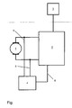
- FIG. Shows a schematic representation of the device according to the invention.
- the device comprises an electric motor 1 of an electric power steering system of a motor vehicle, which is coupled to a steering control unit 2, which in turn is connected to a steering angle sensor 3 for detecting changes in the angle of rotation of a steering column acted upon by the electric motor 1.
- evaluation electronics 4 are provided, which are connected to live lines 5 of the electric motor 1 leading to the steering control unit 2 and act on the steering control unit 2 via a stimulus line 6.
- the steering control unit 2 and the steering angle sensor 3 are in an idle state in which they absorb a relatively low quiescent current from the vehicle electrical system.
- the electric motor 1 is also set in rotation and acts here as a generator.
- the voltage signal of the electric motor 1 is detected and evaluated by the evaluation electronics 4.
- the evaluation electronics 4 controls the steering control unit 2 via the stimulus line 6 and sets this and the steering angle sensor into an operating state in order to detect the change in the angle of rotation of the steering wheel.
- the steering control unit 2 then calculates a new one Value for a steering angle and saves this value.
- the evaluation electronics 4 puts the steering control device 2 and the steering angle sensor 3 back into the idle state.
- the new value for the steering angle stored in the steering control device 2 serves as the basis for calculating further values which result from changes in the angle of rotation of the steering column both when the ignition is switched off and when it is switched on.
Landscapes
- Engineering & Computer Science (AREA)
- Chemical & Material Sciences (AREA)
- Combustion & Propulsion (AREA)
- Transportation (AREA)
- Mechanical Engineering (AREA)
- Steering Control In Accordance With Driving Conditions (AREA)
- Measurement Of Length, Angles, Or The Like Using Electric Or Magnetic Means (AREA)
- Length Measuring Devices With Unspecified Measuring Means (AREA)
- Power Steering Mechanism (AREA)
Applications Claiming Priority (2)
| Application Number | Priority Date | Filing Date | Title |
|---|---|---|---|
| DE10210363A DE10210363A1 (de) | 2002-03-08 | 2002-03-08 | Vorrichtung zur Erfassung einer Drehwinkeländerung einer Lenksäule |
| DE10210363 | 2002-03-08 |
Publications (3)
| Publication Number | Publication Date |
|---|---|
| EP1342648A2 true EP1342648A2 (fr) | 2003-09-10 |
| EP1342648A3 EP1342648A3 (fr) | 2007-04-11 |
| EP1342648B1 EP1342648B1 (fr) | 2012-02-01 |
Family
ID=27740719
Family Applications (1)
| Application Number | Title | Priority Date | Filing Date |
|---|---|---|---|
| EP03004576A Expired - Lifetime EP1342648B1 (fr) | 2002-03-08 | 2003-02-28 | Système pour mesurer l'ampleur des rotations d'une colonne de direction |
Country Status (3)
| Country | Link |
|---|---|
| EP (1) | EP1342648B1 (fr) |
| AT (1) | ATE543715T1 (fr) |
| DE (1) | DE10210363A1 (fr) |
Cited By (2)
| Publication number | Priority date | Publication date | Assignee | Title |
|---|---|---|---|---|
| EP2050658A1 (fr) * | 2007-10-17 | 2009-04-22 | Continental Automotive GmbH | Système de direction |
| WO2011082852A1 (fr) * | 2009-12-16 | 2011-07-14 | Robert Bosch Gmbh | Procédé et dispositif permettant de faire fonctionner un appareil de commande destiné à détecter la position de l'induit d'un moteur électrique |
Families Citing this family (4)
| Publication number | Priority date | Publication date | Assignee | Title |
|---|---|---|---|---|
| EP2486373B1 (fr) * | 2009-10-09 | 2017-01-04 | Baumer IVO GmbH & Co. KG | Indicateur de position doté d'une détermination de position à rotation multiple |
| EP2312274A1 (fr) * | 2009-10-09 | 2011-04-20 | Baumer Innotec AG | Indicateur de position doté d'une détermination de position à rotation multiple |
| DE102010045618A1 (de) | 2010-09-17 | 2012-03-22 | Thyssenkrupp Presta Ag | Vorrichtung zur Erfassung des Drehwinkels einer Lenksäule |
| DE102013104586B4 (de) * | 2013-05-06 | 2016-09-15 | Robert Bosch Automotive Steering Gmbh | Verfahren zu fortlaufenden Bestimmung eines Lenkwinkels oder einer den Lenkwinkel charakterisierenden Größe |
Family Cites Families (5)
| Publication number | Priority date | Publication date | Assignee | Title |
|---|---|---|---|---|
| JPH02240507A (ja) * | 1989-03-14 | 1990-09-25 | Fuji Heavy Ind Ltd | 車両用舵角センサの消費電力低減方法 |
| JP3040570B2 (ja) * | 1992-01-09 | 2000-05-15 | 三菱重工業株式会社 | バッテリ動作型エンコーダ |
| JPH11125537A (ja) * | 1997-10-21 | 1999-05-11 | Niles Parts Co Ltd | 車両用操舵角検出装置 |
| DE19820774A1 (de) * | 1998-05-08 | 1999-11-18 | Danfoss As | Hydraulische Flügelzellenmaschine |
| JP2000088605A (ja) * | 1998-09-17 | 2000-03-31 | Tokai Rika Co Ltd | 絶対位置検出装置 |
-
2002
- 2002-03-08 DE DE10210363A patent/DE10210363A1/de not_active Withdrawn
-
2003
- 2003-02-28 AT AT03004576T patent/ATE543715T1/de active
- 2003-02-28 EP EP03004576A patent/EP1342648B1/fr not_active Expired - Lifetime
Cited By (4)
| Publication number | Priority date | Publication date | Assignee | Title |
|---|---|---|---|---|
| EP2050658A1 (fr) * | 2007-10-17 | 2009-04-22 | Continental Automotive GmbH | Système de direction |
| WO2011082852A1 (fr) * | 2009-12-16 | 2011-07-14 | Robert Bosch Gmbh | Procédé et dispositif permettant de faire fonctionner un appareil de commande destiné à détecter la position de l'induit d'un moteur électrique |
| CN102652289A (zh) * | 2009-12-16 | 2012-08-29 | 罗伯特·博世有限公司 | 用于探测电动机的电枢位置的控制器的运行方法和装置 |
| CN102652289B (zh) * | 2009-12-16 | 2015-03-25 | 罗伯特·博世有限公司 | 用于探测电动机的电枢位置的控制器的运行方法和装置 |
Also Published As
| Publication number | Publication date |
|---|---|
| EP1342648B1 (fr) | 2012-02-01 |
| ATE543715T1 (de) | 2012-02-15 |
| DE10210363A1 (de) | 2003-10-09 |
| EP1342648A3 (fr) | 2007-04-11 |
Similar Documents
| Publication | Publication Date | Title |
|---|---|---|
| DE102015213304A1 (de) | Elektromechanische Servolenkung | |
| EP2077959B1 (fr) | Prodédé de réglage ou de commande d'une unité d'entraînement servo dans un système de direction d'un véhicule et système de direction correspondant | |
| DE10220162B4 (de) | Elektrische Servolenkvorrichtung | |
| DE102005023456B4 (de) | Elektronische Steuereinheit, elektrisch unterstützte Lenkvorrichtung und Lenkeinheit mit variablem Übersetzungsverhältnis | |
| DE4429331A1 (de) | Steuervorrichtung für reversiblen Motor und motorangetriebenes Servolenkungssystem für Motorfahrzeug unter Benutzung derselben | |
| DE102020111606B4 (de) | Drehmomentbasierte fahrzeugpfadvorhersage | |
| EP3247613B1 (fr) | Système de direction permettant une conduite automatisée d'un véhicule automobile | |
| DE10249369A1 (de) | Steuervorrichtung für ein motorangesteuertes Servolenksystem eines Kraftfahrzeugs | |
| EP1190936A1 (fr) | Niveau de repli supplémentaire au cas de panne de capteurs d'angle pour des systèmes "steer-by-wire" sans connection de repli mécanique/hydraulique | |
| WO2000072100A1 (fr) | Systeme de regulation avec surveillance de securite assistee par modele d'un organe de positionnement a regulation electronique monte dans un vehicule automobile | |
| DE69013559T2 (de) | Von einem Motor angetriebene Servolenkung. | |
| WO2011154257A1 (fr) | Détermination d'une sensation de point milieu pour systèmes de direction assistée électrique | |
| EP2285641A1 (fr) | Dispositif et procédé permettant de faire fonctionner un ensemble technique comprenant une machine d'entraînement électrique | |
| DE60131415T2 (de) | Fehlererkennungsverfahren für elektronische lenksysteme | |
| DE102004022493A1 (de) | Lenkung mit variabler Lenkübersetzung | |
| DE10303861B4 (de) | Verfahren und Vorrichtung zur Kompensation des Betriebsstroms für ein elektrisches Lenksystem eines Kraftfahzeugs | |
| DE102013104586B4 (de) | Verfahren zu fortlaufenden Bestimmung eines Lenkwinkels oder einer den Lenkwinkel charakterisierenden Größe | |
| DE4425095C2 (de) | Elektrisch betriebene Servolenkungs-Steuereinheit | |
| EP1342648B1 (fr) | Système pour mesurer l'ampleur des rotations d'une colonne de direction | |
| DE19908357A1 (de) | Sicherheitsvorrichtung für ein aktives Lenksystem für Kraftfahrzeuge | |
| DE10025875B4 (de) | Lenksystem mit elektrischem Antrieb | |
| DE102014208926A1 (de) | Ermittlungsvorrichtung zum Ermitteln eines Unterstützungsmomentes und Unterstützungsvorrichtung sowie Verfahren zum Unterstützen eines von einem Fahrer auf ein Lenksystem des Fahrzeugs aufgebrachten Lenkmomentes | |
| EP1868838B1 (fr) | Chariot elevateur | |
| DE102012004502A1 (de) | Verfahren zum automatisierten Einparken eines mit einem aktiven Parklenkassistenzsystem und einer Überlagerungslenkvorrichtung ausgestatteten Kraftfahrzeugs | |
| EP1568575B1 (fr) | Procédé de commande d'un système de direction avec configuration de modes d'opération |
Legal Events
| Date | Code | Title | Description |
|---|---|---|---|
| PUAI | Public reference made under article 153(3) epc to a published international application that has entered the european phase |
Free format text: ORIGINAL CODE: 0009012 |
|
| AK | Designated contracting states |
Kind code of ref document: A2 Designated state(s): AT BE BG CH CY CZ DE DK EE ES FI FR GB GR HU IE IT LI LU MC NL PT SE SI SK TR |
|
| AX | Request for extension of the european patent |
Extension state: AL LT LV MK RO |
|
| PUAL | Search report despatched |
Free format text: ORIGINAL CODE: 0009013 |
|
| AK | Designated contracting states |
Kind code of ref document: A3 Designated state(s): AT BE BG CH CY CZ DE DK EE ES FI FR GB GR HU IE IT LI LU MC NL PT SE SI SK TR |
|
| AX | Request for extension of the european patent |
Extension state: AL LT LV MK RO |
|
| 17P | Request for examination filed |
Effective date: 20070709 |
|
| 17Q | First examination report despatched |
Effective date: 20070903 |
|
| AKX | Designation fees paid |
Designated state(s): AT BE BG CH CY CZ DE DK EE ES FI FR GB GR HU IE IT LI LU MC NL PT SE SI SK TR |
|
| RAP1 | Party data changed (applicant data changed or rights of an application transferred) |
Owner name: GM GLOBAL TECHNOLOGY OPERATIONS, INC. |
|
| RAP1 | Party data changed (applicant data changed or rights of an application transferred) |
Owner name: GM GLOBAL TECHNOLOGY OPERATIONS LLC |
|
| GRAP | Despatch of communication of intention to grant a patent |
Free format text: ORIGINAL CODE: EPIDOSNIGR1 |
|
| GRAS | Grant fee paid |
Free format text: ORIGINAL CODE: EPIDOSNIGR3 |
|
| GRAA | (expected) grant |
Free format text: ORIGINAL CODE: 0009210 |
|
| AK | Designated contracting states |
Kind code of ref document: B1 Designated state(s): AT BE BG CH CY CZ DE DK EE ES FI FR GB GR HU IE IT LI LU MC NL PT SE SI SK TR |
|
| REG | Reference to a national code |
Ref country code: GB Ref legal event code: FG4D Free format text: NOT ENGLISH |
|
| REG | Reference to a national code |
Ref country code: AT Ref legal event code: REF Ref document number: 543715 Country of ref document: AT Kind code of ref document: T Effective date: 20120215 Ref country code: CH Ref legal event code: EP |
|
| REG | Reference to a national code |
Ref country code: DE Ref legal event code: R096 Ref document number: 50314197 Country of ref document: DE Effective date: 20120329 |
|
| REG | Reference to a national code |
Ref country code: NL Ref legal event code: VDEP Effective date: 20120201 |
|
| PG25 | Lapsed in a contracting state [announced via postgrant information from national office to epo] |
Ref country code: NL Free format text: LAPSE BECAUSE OF FAILURE TO SUBMIT A TRANSLATION OF THE DESCRIPTION OR TO PAY THE FEE WITHIN THE PRESCRIBED TIME-LIMIT Effective date: 20120201 |
|
| PGFP | Annual fee paid to national office [announced via postgrant information from national office to epo] |
Ref country code: DE Payment date: 20120510 Year of fee payment: 10 |
|
| REG | Reference to a national code |
Ref country code: IE Ref legal event code: FD4D |
|
| BERE | Be: lapsed |
Owner name: GM GLOBAL TECHNOLOGY OPERATIONS LLC Effective date: 20120228 |
|
| PG25 | Lapsed in a contracting state [announced via postgrant information from national office to epo] |
Ref country code: FI Free format text: LAPSE BECAUSE OF FAILURE TO SUBMIT A TRANSLATION OF THE DESCRIPTION OR TO PAY THE FEE WITHIN THE PRESCRIBED TIME-LIMIT Effective date: 20120201 Ref country code: GR Free format text: LAPSE BECAUSE OF FAILURE TO SUBMIT A TRANSLATION OF THE DESCRIPTION OR TO PAY THE FEE WITHIN THE PRESCRIBED TIME-LIMIT Effective date: 20120502 Ref country code: PT Free format text: LAPSE BECAUSE OF FAILURE TO SUBMIT A TRANSLATION OF THE DESCRIPTION OR TO PAY THE FEE WITHIN THE PRESCRIBED TIME-LIMIT Effective date: 20120601 |
|
| PGFP | Annual fee paid to national office [announced via postgrant information from national office to epo] |
Ref country code: GB Payment date: 20120502 Year of fee payment: 10 |
|
| PG25 | Lapsed in a contracting state [announced via postgrant information from national office to epo] |
Ref country code: MC Free format text: LAPSE BECAUSE OF NON-PAYMENT OF DUE FEES Effective date: 20120229 Ref country code: CY Free format text: LAPSE BECAUSE OF FAILURE TO SUBMIT A TRANSLATION OF THE DESCRIPTION OR TO PAY THE FEE WITHIN THE PRESCRIBED TIME-LIMIT Effective date: 20120201 |
|
| REG | Reference to a national code |
Ref country code: CH Ref legal event code: PL |
|
| PG25 | Lapsed in a contracting state [announced via postgrant information from national office to epo] |
Ref country code: SI Free format text: LAPSE BECAUSE OF FAILURE TO SUBMIT A TRANSLATION OF THE DESCRIPTION OR TO PAY THE FEE WITHIN THE PRESCRIBED TIME-LIMIT Effective date: 20120201 Ref country code: DK Free format text: LAPSE BECAUSE OF FAILURE TO SUBMIT A TRANSLATION OF THE DESCRIPTION OR TO PAY THE FEE WITHIN THE PRESCRIBED TIME-LIMIT Effective date: 20120201 Ref country code: SE Free format text: LAPSE BECAUSE OF FAILURE TO SUBMIT A TRANSLATION OF THE DESCRIPTION OR TO PAY THE FEE WITHIN THE PRESCRIBED TIME-LIMIT Effective date: 20120201 Ref country code: LI Free format text: LAPSE BECAUSE OF NON-PAYMENT OF DUE FEES Effective date: 20120229 Ref country code: CH Free format text: LAPSE BECAUSE OF NON-PAYMENT OF DUE FEES Effective date: 20120229 Ref country code: IE Free format text: LAPSE BECAUSE OF FAILURE TO SUBMIT A TRANSLATION OF THE DESCRIPTION OR TO PAY THE FEE WITHIN THE PRESCRIBED TIME-LIMIT Effective date: 20120201 Ref country code: EE Free format text: LAPSE BECAUSE OF FAILURE TO SUBMIT A TRANSLATION OF THE DESCRIPTION OR TO PAY THE FEE WITHIN THE PRESCRIBED TIME-LIMIT Effective date: 20120201 Ref country code: CZ Free format text: LAPSE BECAUSE OF FAILURE TO SUBMIT A TRANSLATION OF THE DESCRIPTION OR TO PAY THE FEE WITHIN THE PRESCRIBED TIME-LIMIT Effective date: 20120201 |
|
| PG25 | Lapsed in a contracting state [announced via postgrant information from national office to epo] |
Ref country code: IT Free format text: LAPSE BECAUSE OF FAILURE TO SUBMIT A TRANSLATION OF THE DESCRIPTION OR TO PAY THE FEE WITHIN THE PRESCRIBED TIME-LIMIT Effective date: 20120201 Ref country code: SK Free format text: LAPSE BECAUSE OF FAILURE TO SUBMIT A TRANSLATION OF THE DESCRIPTION OR TO PAY THE FEE WITHIN THE PRESCRIBED TIME-LIMIT Effective date: 20120201 |
|
| PLBE | No opposition filed within time limit |
Free format text: ORIGINAL CODE: 0009261 |
|
| STAA | Information on the status of an ep patent application or granted ep patent |
Free format text: STATUS: NO OPPOSITION FILED WITHIN TIME LIMIT |
|
| PG25 | Lapsed in a contracting state [announced via postgrant information from national office to epo] |
Ref country code: BE Free format text: LAPSE BECAUSE OF NON-PAYMENT OF DUE FEES Effective date: 20120228 |
|
| 26N | No opposition filed |
Effective date: 20121105 |
|
| REG | Reference to a national code |
Ref country code: FR Ref legal event code: ST Effective date: 20130104 |
|
| PG25 | Lapsed in a contracting state [announced via postgrant information from national office to epo] |
Ref country code: FR Free format text: LAPSE BECAUSE OF NON-PAYMENT OF DUE FEES Effective date: 20120402 |
|
| REG | Reference to a national code |
Ref country code: DE Ref legal event code: R097 Ref document number: 50314197 Country of ref document: DE Effective date: 20121105 |
|
| REG | Reference to a national code |
Ref country code: AT Ref legal event code: MM01 Ref document number: 543715 Country of ref document: AT Kind code of ref document: T Effective date: 20120228 |
|
| PG25 | Lapsed in a contracting state [announced via postgrant information from national office to epo] |
Ref country code: ES Free format text: LAPSE BECAUSE OF FAILURE TO SUBMIT A TRANSLATION OF THE DESCRIPTION OR TO PAY THE FEE WITHIN THE PRESCRIBED TIME-LIMIT Effective date: 20120512 |
|
| PG25 | Lapsed in a contracting state [announced via postgrant information from national office to epo] |
Ref country code: AT Free format text: LAPSE BECAUSE OF NON-PAYMENT OF DUE FEES Effective date: 20120228 |
|
| PG25 | Lapsed in a contracting state [announced via postgrant information from national office to epo] |
Ref country code: BG Free format text: LAPSE BECAUSE OF FAILURE TO SUBMIT A TRANSLATION OF THE DESCRIPTION OR TO PAY THE FEE WITHIN THE PRESCRIBED TIME-LIMIT Effective date: 20120501 |
|
| GBPC | Gb: european patent ceased through non-payment of renewal fee |
Effective date: 20130228 |
|
| REG | Reference to a national code |
Ref country code: DE Ref legal event code: R119 Ref document number: 50314197 Country of ref document: DE Effective date: 20130903 |
|
| PG25 | Lapsed in a contracting state [announced via postgrant information from national office to epo] |
Ref country code: DE Free format text: LAPSE BECAUSE OF NON-PAYMENT OF DUE FEES Effective date: 20130903 Ref country code: GB Free format text: LAPSE BECAUSE OF NON-PAYMENT OF DUE FEES Effective date: 20130228 |
|
| PG25 | Lapsed in a contracting state [announced via postgrant information from national office to epo] |
Ref country code: TR Free format text: LAPSE BECAUSE OF FAILURE TO SUBMIT A TRANSLATION OF THE DESCRIPTION OR TO PAY THE FEE WITHIN THE PRESCRIBED TIME-LIMIT Effective date: 20120201 |
|
| PG25 | Lapsed in a contracting state [announced via postgrant information from national office to epo] |
Ref country code: LU Free format text: LAPSE BECAUSE OF NON-PAYMENT OF DUE FEES Effective date: 20120228 |
|
| PG25 | Lapsed in a contracting state [announced via postgrant information from national office to epo] |
Ref country code: HU Free format text: LAPSE BECAUSE OF FAILURE TO SUBMIT A TRANSLATION OF THE DESCRIPTION OR TO PAY THE FEE WITHIN THE PRESCRIBED TIME-LIMIT Effective date: 20030228 |